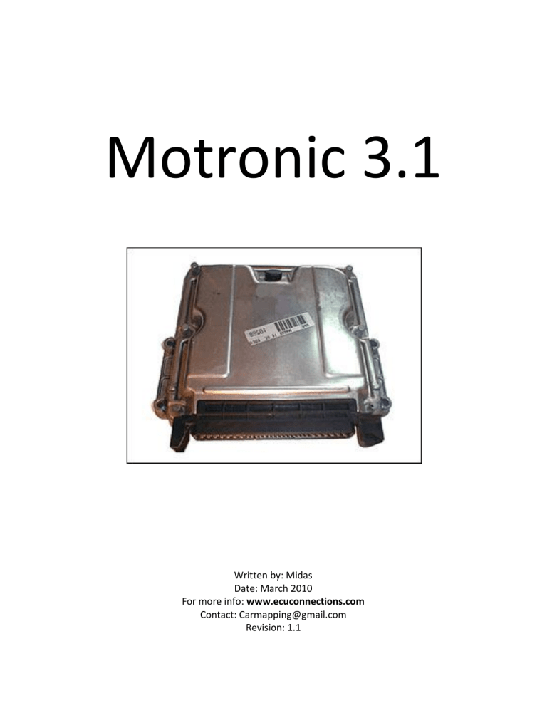
Motronic 3.1 Written by: Midas Date: March 2010 For more info: www.ecuconnections.com Contact: [email protected] Revision: 1.1 Index: Introduction 1. General 2. The rev limiter 3. Ignition at closed throttle 4. Ignition at part throttle 5. Ignition at WOT 6. Dwell angle map 7. Injection at closed throttle 8. Injection at part throttle 9. Injection at WOT 10. Lambda map 11. Transition compensation map 12. Idle rpm map 13. Deceleration injection after cut off 14. Correction of injection 15. Other correction maps 16. Checksum 17. I am just a beginner, how can i tune my engine? 18. Goodies for the 402 computer owner. Conclusion 3 4 6 7 9 10 11 13 14 15 15 16 17 17 18 18 18 19 19 20 Introduction: The motronic ECU's are used in a lot of cars. I have the most experience in the motronic 3.1 used in the BMW e36 series. This document may cover information that is the same for other motronic series. The motronic 3.1 has one 27C256 UV EPROM inside. It has a DIL28 package and is mounted in a socket, so removing it is easy. 1. General: The point of the ignition is determined in a motronic 3.1 by the schematic shown in picture 1.1 Picture 1.1: The schematic overview of the ignition. In this schematic you can see that there are a lot of corrections and checks before the original ignition point reached the bottom of the schematic. For injection calculation the motronic 3.1 uses the schematic shown in picture 1.2. Picture 1.2: The schematic overview of the injection. Also in this schematic you can see that there are a lot of corrections before there is a effective injection timing. 2. The rev limiter: The rev limiter in motronic 3.1 is very easy to find. Open the file and search for the value 90 65 (hexadecimal). The rev limiter will be located in front of the maps (most of the time). The rev limiter works by cutting the fuel off. When the rpm has dropped below the rev limit there will be applied fuel again to the engine. How much fuel is injected after a cut-off is regulated by the "deceleration injection after cut-off" map. The average change in rpm when the rev limiter is hit is around 150rpm. The engine will cycle between 6425 to 6575rpm when rev limit is at 6500rpm. The calculation method for the rev limiter is as follows: 90 65 Swap the bytes gives: 6590 Convert it into decimal gives: 26000 Divide this by 4 gives: 6500 RPM So if we want the rev limiter at 7000 RPM we do the following: 7000 Multiply this by 4 gives: 28000 Convert this into hexadecimal gives: 6D60 Swap the bytes gives: 60 6D The ignition maps: The maps discussed below are only the "base" maps. It is enough to change them only if u want to advance the ignition. Also the dwell angle map will be discussed. 3. Ignition at Closed Throttle The ignition at closed throttle map is an 8x1 map which can look like picture 3.1. Picture 3.1: The ignition advantage at closed throttle. The code looks like this in the hex dump: CF 08 01 01 08 08 A4 2F 2D 2B 2B 2B 0D 2D 13 30 1C 32 The green part is the axis identifier. The red part are the axis numbers. The light blue map are the values inside the map CF = this means that this axis is RPM 08 = this means that the map is 8 bytes long As you see this the first thing you will notice is that the axis does not make any sense. What axis is 1, 1, 8, 8, 13, 19, 28, 164? Why does this axis have more the same values? This is because the axis values are not absolute values, but the differences between the axis numbers. The factor used for RPM (CF) is 40. So we need to multiply all RPM values by 40 to get a "human" readout. You now see that the difference between 560-600RPM (on the axis) is exactly 40. And the first number off the axis is "1". So 1x40 = 40, so 40 is the first difference in the axis. WinOLS will auto detect this and apply the "Eprom subtract" mode to the axis. Now we know how to determine the axis, we need to know how factor and offset from the ignition advantage. The values stored in all the ignition maps are absolute values. The factor for the ignition is 0.75 and the offset is -22.5. If we apply that factor and offset we get degrees BTDC. In the picture 3.2 you can see if you need this map when you changed camshafts. Degree's camshafts 270 280 290 300 310 Required degrees BTDC 10-12 10-14 12-16 14-18 16-20 Picture 3.2: The ignition advantage at closed throttle specific for camshaft. 4. Ignition at Part Throttle The ignition at part throttle is a 12x16 map, and looks like picture 4.1. Picture 4.1: The Part throttle ignition advantage map. The factor for RPM is 40, and the offset 0. For the Load the factor is 0.715, the offset is 0. The factor for the ignition advantage is 0.75 and the offset is -22.5. If you change this map I suggest adding not more than 10% ignition advantage. Also in that case using fuel with the highest possible octane number is recommended (95-101). When you "over tune" this map it will result in damage to the engine. For proper tuning knock-detection equipment is needed. If we look into the header we determine D5 as the axis descriptor of Load. The naming and numbers on the axes work the same as on page 6. 5. Ignition at Wide Open Throttle The ignition at wide open throttle is a 6x16 map which looks like picture 5.1. Picture 5.1: The WOT ignition advantage map. The factor for RPM is 40, and the offset 0. For the Load the factor is 0.715, the offset is 0. The factor for the ignition advantage is 0.75 and the offset is -22.5. If you change this map I suggest adding not more than 10% ignition advantage. Also in that case using fuel with the highest possible octane number is recommended (95-101). When you "over tune" this map it will result in damage to the engine. For proper tuning knock-detection equipment is needed. If we look into the header we determine D5 as the axis descriptor of Load. The naming and numbers on the axes work the same as on page 6. 6. Dwell angle map The Dwell angle map is a 7x12 map which looks like picture 6.1. Picture 6.1: Dwell angle map. This map controls the dwell angle by voltage (D8) which uses factor 0.068, and rpm (CF) which uses factor 40. Dwell period is the time during which the primary circuit is closed and primary current flows through the ignition coil, given in crankshaft or distributor shaft degrees and therefore also called dwell angle. The injection maps: There are 3 base injection maps in this motronic. -Injection at Closed Throttle -Injection at Part Throttle -Injection at Wide Open Throttle Beside those maps there are also the following maps: -Lambda map -Transition compensation map -Idle rpm map -Deceleration injection after fuel cut-off map -Correction of injection length (voltage) map -Other correction maps 7. Injection at Closed Throttle The Injection at closed throttle map is a 3x6 map, and looks something like picture 7.1. Picture 7.1: The closed throttle injection map. The factor for RPM is 40, and the offset 0. For the Load the factor is 0.715, the offset is 0. The injection map does not have absolute values in it. The values are the correction-values for the, by the ECU, calculated injection pulse length. The value 128 is set as the zero-point. Examples: Value 135 in this map means: 135 - 128 = 7 So the ECU will add 7 to the calculated injection pulse length. Value 119 in this map means: 119 - 128 = -9 So the ECU will subtract 9 from the calculated injection pulse length. 8. Injection at Part Throttle The Injection at part throttle is a 12x16 map which looks like picture 8.1. Picture 8.1: The part throttle injection map. The factor for RPM is 40, and the offset 0. For the Load the factor is 0.715, the offset is 0. The injection map does not have absolute values in it. The values are the correction-values for the, by the ECU, calculated injection pulse length. The value 128 is set as the zero-point. Just like the closed throttle map. 9. Injection at Wide Open Throttle The Injection at WOT is a 1x16 map which looks like picture 9.1. Picture 9.1: The WOT injection map. The factor for RPM is 40, and the offset 0. For the Load the factor is 0.715, the offset is 0. The injection map does not have absolute values in it. The values are the correction-values for the, by the ECU, calculated injection pulse length. The value 128 is set as the zero-point. Just like the closed and part throttle map. To change this map in a good way you need a wideband lambda sensor (or a dyno) to achieve the proper Air Fuel Ratio (AFR). 10. Lambda map The Lambda maps consist out of 5 maps controlling the lambda closed loop. 2 maps are 6x1 and 3 maps are 4x1 maps. The maps are located close to each other. In case of the BMW e36 402 computer with 098 software they are located at address 7870-78A1. 11. Transition compensation map The transition compensation map is a 6x6 map which looks like picture 11.1. This map is needed to compensate for load changes due to throttle-valve movements. The further the injectors are from the cylinder head the more complex this map will be. Because the fuel evaporates/form droplets and makes a thin fuel-film on the intake not all the injected fuel will arrive into the combustion chamber the same moment as the throttle is hit. Picture 11.1: Transition compensation map. The axes are Load (D5) using factor 0.715 and RPM (CF) using factor 40. The height of the map indicates how much fuel is injected. 12. Idle rpm map The idle rpm map controls the idle rpm depending on the coolant temperature and looks like picture 12.1. Picture 12.1: The idle rpm map. This is a 4x1 map with one axis, coolant (D7). The factor for coolant is 0.75 and the offset is -48. For RPM (CF) the factor is 40. When you changed camshafts it might be needed to change the idle rpm. You can use picture 12.2 for setting the right idle speed. Degree's camshafts 270 280 290 300 310 Required idle engine speed 600-800 RPM 800-1000 RPM 1000-1200 RPM 1200-1400 RPM 1300-1500 RPM Picture 12.2: The engine speed at idle with different camshafts. 13. Deceleration injection after cut-off map The deceleration injection after fuel cut-off map controls the quantity of injected fuel after the injection had been cut off by a limiter (rpm or speed). The deceleration injection after fuel cutoff map is a 7x6 map shown in picture 13.1. The map has 2 axis, rpm and Throttle valve angle. The rpm( CF) has factor 40. The Throttle valve angle uses factor 0.562500. Picture 13.1: The deceleration injection after cut off map. 14. Correction of injection length The correction of injection length (voltage) map is a 5x1 map which looks like picture 14.1. Picture 14.1: The injection correction map. The factor for voltage is 0.068. This map correct the injection length when the voltage is low(during starting the engine). 15. Other correction maps There are a lot of 3x1, 4x1 and 5x1 correction maps for injection length. Most of them are a function of engine coolant temperature or rpm. 16. Checksum The Checksum used in this ECU is a partial checksum. This means that every bit you add, you have to subtract that from empty space in the EPROM. Empty memory can be recognized by "fields of FF FF FF FF's". This way the total of all the bytes in the file together stays the same. 17. I am just a beginner, how can I tune my engine? When you want more power out of the stock car it is enough to change the ignition an injection part throttle and WOT maps. Of course you need to correct the checksum after changing the maps. The only proper way to tune this type of car is by measuring the AFR and the knock-limit. 18. Goodies for the 402 computer owner Since I wrote this file using the 0261 200 402 computer from a BMW e36 325i with software 098 I found almost all the useful axis descriptors and map addresses. Here they are: Descriptor D4 D5 D7 D8 21 CF Address 6B1E 6B20 6C1A 6C1B 70B9 7210 7072 7234 7264 7369 74C3 7870 787E 788A 7894 789E 74F1 7525 75A5 7706 Name Air temp Load Coolant Voltage Throttle position RPM Factor 0.75 0.715 0.75 0.068 0.5625 40 Map Injector constants Rev limiter speed limiter(only US) speed limiter buffer Correction injection by voltage Injection Idle Idle rpm injection WOT Injection part throttle deceleration after cut off transition compensation Lambda Lambda Lambda Lambda Lambda Ignition idle Ignition WOT Ignition part throttle Dwell angle Offset -48 0 -48 0 0 0 Size 1x1 1x2 1x1 1x1 5x1 3x6 4x1 16x1 12x16 7x6 6x6 6x1 6x1 4x1 4x1 4x1 8x1 6x16 12x16 7x12 Conclusion: All information and values given in this document may be used at own risk. I do not stand in for any problems. Thanks to the members from www.ecuconnections.com and an unnamed Dutch chiptuner I had the possibility to gather this info. I hope you enjoy it.
