LAH 65-K-BSY+ - Hahn Lamellen
Anuncio
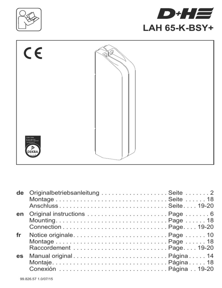
LAH 65-K-BSY+ de Originalbetriebsanleitung . . . . . . . . . . . . . . . . . . . Seite . . . . . . . 2 Montage . . . . . . . . . . . . . . . . . . . . . . . . . . . . . . . . Seite . . . . . . 18 Anschluss . . . . . . . . . . . . . . . . . . . . . . . . . . . . . . . Seite . . . . 19-20 en Original instructions . . . . . . . . . . . . . . . . . . . . . . . Page . . . . . . . 6 Mounting. . . . . . . . . . . . . . . . . . . . . . . . . . . . . . . . Page . . . . . . 18 Connection . . . . . . . . . . . . . . . . . . . . . . . . . . . . . . Page. . . . 19-20 fr Notice originale. . . . . . . . . . . . . . . . . . . . . . . . . . . Page . . . . . . 10 Montage . . . . . . . . . . . . . . . . . . . . . . . . . . . . . . . . Page . . . . . . 18 Raccordement . . . . . . . . . . . . . . . . . . . . . . . . . . . Page. . . . 19-20 es Manual original . . . . . . . . . . . . . . . . . . . . . . . . . . . Página . . . . . 14 Montaje. . . . . . . . . . . . . . . . . . . . . . . . . . . . . . . . . Página . . . . . 18 Conexión . . . . . . . . . . . . . . . . . . . . . . . . . . . . . . . Página . . 19-20 99.826.57 1.0/07/15 Leistungsmerkmale Bestimmungsgemäße Verwendung ® - Lamellenantrieb zum Bedienen von Hahn Lamellen des Typs S9, S9-45°, S9iV, S9iVt-05, S9iVt-05 Allglass und Tairmo - Die Lamelle muss vom Lamellenhersteller für den Einsatz des Antriebes vorbereitet sein - Betriebsspannung 230 V AC - Einsetzbar für Öffnungen zur Rauchableitung sowie für täglichen Lüftungsbetrieb - Nur für Innenmontage geeignet - Mikroprozessorgesteuerte Synchro-Elektronik für sicheren und präzisen Synchronlauf von bis zu 4 Antrieben - Individuell programmierbar über Software SCS - Schutzsystem für die Hauptschließkante Funktionsbeschreibung Sicherheitshinweise Betriebsspannung 230 V AC! Verletzungsgefahr durch Stromschlag! L+N nicht vertauschen! PE anschließen! Vor der Montage / Demontage vom Netz trennen / Spannunsfrei machen!! - Anschluss darf nur durch eine autorisierte Elektrofachkraft erfolgen - Quetschgefahr im handzugänglichen Bereich - Personen aus dem Fahrbereich des Antriebes fernhalten - Kinder von der Steuerung fernhalten - Nur in trockenen Räumen verwenden - Nur für die Innenmontage geeignet Bei Gefahr durch Regen Regenmelder verwenden - Nur unveränderte D+H-Originalteile verwenden Eine LAH 65-K-BSY+ Synchrongruppe kann aus bis zu 4 Antrieben bestehen, welche über einen Bus kommunizieren. Jeder Antrieb hat seine eigene Adresse. Diese ist mittels Software SCS konfigurierbar. Der letzte Antrieb einer Synchrongruppe ist der Master, welcher die restlichen Antriebe, die Slaves, steuert. Kraftdifferenzen zwischen den Antrieben einer Synchrongruppe werden durch eine intelligente Kraft- und Positionsregelung ausgeglichen. Bei Störung bzw. Ausfall eines Antriebes werden alle Antriebe automatisch abgeschaltet. Beiliegenden roten Sicherheitszettel beachten! Konformitätserklärung Entsorgung Wir erklären in alleiniger Verantwortung, dass das unter „Technische Daten“ beschriebene Produkt mit den folgenden Richtlinien übereinstimmt: 2014/30/EU, 2014/35/EU Technische Unterlagen bei: D+H Mechatronic AG, D-22949 Ammersbek Thomas Kern Maik Schmees Vorstand 26.03.2015 Prokurist, Technischer Leiter 2/20 LAH 65-K-BSY+ Elektrogeräte, Zubehör und Verpackungen sollen einer umweltgerechten Wiederverwertung zugeführt werden. Werfen Sie Elektrogeräte nicht in den Hausmüll! Nur für EU-Länder: Gemäß der Europäischen Richtlinie 2012/19/EU über Elektro- und Elektronik-Altgeräte und ihrer Umsetzung in nationales Recht müssen nicht mehr gebrauchsfähige Elektrogeräte getrennt gesammelt und einer umweltgerechten Wiederverwertung zugeführt werden. Deutsch 99.826.57 1.0/07/15 Technische Daten Typ LAH 65-K-BSY+ Versorgung Leistung Drehmoment * Laufgeschindigkeit * Öffnungswinkel * 230 V AC / ±10% / 50 Hz 22 W / 35 V A 0,3 Nm ... 4,5 Nm (entspricht ausgangsseitig 0,6 Nm ... 9 Nm) 3,5°/sek. ... 10,9°/sek. 85 ° Lebensdauer Einschaltdauer Gehäuse Schutzart Temp. Bereich Temp. Standsicherheit Abmessungen B x H x T Zusatzfunktionen * >10 000 Doppelhübe 50 %, Bei Spielzeit 10 Min. Zinkdruckguss IP 54 -5 ... +75 °C 30 min / 300 °C 260 x 71 x 37 mm Schließkantenschutz aktiviert, 3 Wiederholungshübe * Programmierbar mit Software SCS Schließkantenschutz 4°/sek.** ~9°/sek.** 4°/sek.** In Laufrichtung "ZU" verfügt der Antrieb über einen aktiven Schutz für die Hauptschließkante. Bei einer Überlast im Schließbereich 3 und 2 fährt der Antrieb für 10 Sekunden wieder "AUF". Danach fährt der Antrieb wieder "ZU". Sollte nach drei Versuchen ein Einfahren nicht möglich sein, bleibt der Antrieb in dieser Stellung stehen. Zusätzlich verfügt der Antrieb über einen passiven Schutz. Die Schließgeschwindigkeit wird im Schließbereich 2 und 1 reduziert. 8°** 25°** ZU Sc h lie ß 9°/sek.** che rei be AUF An den Nebenschließkanten können deutlich höhere Kräfte auftreten. Quetschgefahr im handzugänglichen Bereich. Laufgeschwindigkeiten ** Werkssparameter Garantie Wartung und Reinigung Die Inspektion und Wartung hat gemäß den D+HWartungshinweisen zu erfolgen. Es dürfen nur original D+H-Ersatzteile verwendet werden. Eine Instandsetzung erfolgt ausschließlich durch D+H. Wischen Sie Verschmutzungen mit einem trockenen, weichen Tuch ab. Verwenden Sie keine Reinigungs- oder Lösemittel. Auf alle D+H-Artikel erhalten Sie 2 Jahre Garantie ab belegter Übergabe der Anlage bis max. 3 Jahre nach Auslieferungsdatum, wenn die Montage bzw. Inbetriebnahme durch einen von D+H autorisierten Service- und Vertriebspartner durchgeführt wurde. Bei Anschluss von D+H-Komponenten an Fremdanlagen oder Vermischung von D+HProdukten mit Teilen anderer Hersteller erlischt die D+H-Garantie. 99.826.57 1.0/07/15 Deutsch LAH 65-K-BSY+ 3/20 Lieferumfang h e b j g d c a f a b c d e f g h j Lamellenantrieb LAH 65-K-BSY+ Linsenschrauben M4 x 12 Linsenschrauben M2,5 x 5 Kabelklemme Anschlusskabel 2,5 m Stecker - 9 polig Grundplatte Blechschrauben ST4,2 x 16 Linsenschrauben M3 x 6 Montagehinweise - Für IP 54:Die Kabelzuführung muss von unten oder hinten erfolgen - Die Lamelle muss vom Lamellenhersteller für den Einsatz des Antriebes vorbereitet sein Montage auf der linken Seite = Werkseinstellung Montage auf der rechten Seite = Programmierung durch SCS-Software erforderlich! Montagelöcher für Tairmo 4/20 LAH 65-K-BSY+ Deutsch 99.826.57 1.0/07/15 Montagelöcher für S9-xxx Inbetriebnahme Störungssuche Der Antrieb darf nicht ohne Lamellenfenster fahren, dieses kann sonst zu Schäden am Antrieb führen! Zur Erstinbetriebnahme und nach Austausch eines Antriebes muss eine Referenzfahrt erfolgen. Hierbei ermittelt der Antrieb seinen Nullpunkt (Zu-Stellung). Dieser einmalige Vorgang wird Nullabgleich genannt. - Antrieb anschließen - Antrieb in ZU-Richtung ansteuern (unabhängig von der Stellung der Lamellen) Nach erfolgter Überlastabschaltung in Laufrichtung "ZU" hat der Antrieb jetzt einen neuen Nullpunkt bekommen. Während der Referenzfahrt darf kein Hinderniss den Lauf der Lamellen beeinträchtigen. Wärend der Referenzfahrt ist der Handschutz (Quetschgefahr) im Handeingreiffbereich deaktiviert! Sichtprüfung: Es darf nur ein Master Antrieb vorhanden sein. Der Master hat, entsprechend der Anzahl der gesamt Antriebe, die letzte Adresse. Die Adresse ist auf den Antrieb aufgeklebt. Slave Antriebe sind abwärts durchnummeriert. Bsp.: In einer Gruppe, bestehend aus 3 Antrieben, gibt es einen Master 3, einen Slave 2 und einen Slave 1 Antrieb. Achtung: gilt nur bei Auslieferzustand. Sobald die Antriebe mittels SCS neu konfiguriert wurden gilt die werksseitige Adressierung nicht mehr! Verdrahtung: Ist die Gruppe ordnungsgemäß verdrahtet? Siehe dazu Anschlusspläne Referenzfahrt: Nullabgleich durchführen. Software SCS oder spezieller Magnet MAG 502 wird benötigt. D+H Service anrufen: Konfigurierung der Antriebe erforderlich. Die Software SCS wird benötigt. Referenzfahrt (Nullabgleich) – Einzelantrieb* Spezialmagnet MAG 502 1. Antrieb einfahren. Eventuell öffnet und schließt der Antrieb dreimal (Schließkantenschutz), und verbleibt dann in der letzten Position. 2. Warten bis der Antrieb ganz zugefahren ist. 3. Am Antrieb muss in ZU-Richtung weiter Spannung anliegen. 4. Magnet gemäß Skizze an den Antrieb halten. 5. Durch den Magneten erhält der Antrieb einen erneuten ZU-Befehl und führt einen Nullabgleich bei einer Überlastabschaltung durch. 6. Dieses wird durch ein leises Brummen des Antriebes bestätigt. 7. In einer Synchrongruppe muss jeder Antrieb des Set´s einzeln genullt werden. * Antriebsgruppe: Die Software SCS wird benötigt. 99.826.57 1.0/07/15 Deutsch LAH 65-K-BSY+ 5/20 Intended use Performance Features - Louvre drive for infinitely electric opening and closing of Hahn® louvre windows of type S9, S9-45°, S9iV, S9iVt-05, S9iVt-05 All-glass and Tairmo - The louvre must be prepared by the louvre manufacturer for the application of the drive - Microprocessor controlled synchro electronics for a precise synchronous run of up to 4 drives - Individually programmable (via SCS software) - Protection system for the main closing edge - Operating voltage 230 V AC - Usable for smoke extraction as well as daily ventilation - Only for inside mounting Functional description Safety notes Operating voltage 230 V AC! Risk of injury from electric shock! Do not reverse L+N! Connect PE! Before mounting / demounting completely disconnected and volt-free! - Connection has to be carried out only by an authorized electrical specialist - Danger of violent pressure in handaccessible area - Keep away People from the operating area of the drive - Keep away children from the control - Use only in dry rooms - Only for inside mounting. Use rain detector with danger of rain - Just use unchanged original D+H parts A synchron-group (LAH 65-K-BSY+) can be count up to 4 drives, which communicate by a bus. Each drive has it’s own adress. This adress is configurable with SCS software. The last drive of a synchron-group is the master, which controls the other drives, the slaves. Different forces between the drives of a group will balanced with intelligent force- and position control. In case of malfunction respective cutoff of a drive, all drives will shut down from the master-drive. Observe enclosed red safety slip! Disposal Declaration of Conformity We declare under our sole responsibility that the product described under “Technical Data” is in conformity with the following directives: 2014/30/EU, 2014/35/EU Technical file at: D+H Mechatronic AG, D-22949 Ammersbek Thomas Kern Maik Schmees Member of the Board 26.03.2015 Authorized signatory, Technical Director 6/20 LAH 65-K-BSY+ Electrical devices, accessories and packaging should be sorted for environmental-friendly recycling. Do not dispose electrical devices into household waste! Only for EC countries: According the European Guideline 2012/19/EU for waste electrical and electronic equipment and its implementation into national right, electrcal devices that are no longer usable must be collected separately and disposed of in an environmentally correct manner. English 99.826.57 1.0/07/15 Technical Data Type LAH 65-K-BSY+ Power supply Power consumption Torque * Running speed * Opening angle * 230 V AC / ±10% / 50 Hz 22 W / 35 VA 0,3 Nm ... 4,5 Nm (corresponds 0,6 Nm ... 9 Nm on the output side) 3,5°/sec. ... 10,9°/sec. 85 ° Lifetime Duty cycle Housing Ingress protection Temperature range Fire stability Dimensions W x H x D Additional functions * >10 000 double strokes 50 %, With cycle time 10 minutes die-cast zinc IP 54 -5 ... +75 °C 30 min / 300 °C 260 x 71 x 37 mm Closing edge protection activated, 3 stroke repeatings * Programmable with SCS software Closing edge protection 4°/sec.** ~9°/sec.** 4°/sec.** In the "CLOSE" direction the drive has an active protection for the main closing edge. If there is an overload in the closing range 3 and 2, the drive runs "OPEN" for 10 seconds, then "CLOSE" again. If after three attempts closing is not possible, the drive remains in this position. In addition, the drive is equipped with passive protection. The closing speed in closing range 2 and 1 is reduced. 8°** 25°** CLOSED Ra es ng Clos ur e 9°/sec.** OPEN Significantly greater forces can be exerted at the secondary closing edges. Danger of crushing hands and fingers! Running speed ** factory parameter Guarantee Maintenance and cleaning Inspection and maintenance has to be carried out according to D+H maintenance notes. Only original D+H spare parts may be used. Repair is to be carried out exclusively by D+H. Wipe away debris or contamination with a dry, soft cloth. Do not use cleaning agents or solvents. 99.826.57 1.0/07/15 You will get 2 years guarantee for all D+H products from date of verified handing over of the system up to maximal 3 years after date of delivery, when mounting and starting has been carried out by an authorized D+H-distributor. D+H guarantee is expired, with connection of D+H components with external systems or with mixing of D+H products with parts of other manufacturers. English LAH 65-K-BSY+ 7/20 Extent of supply h e b j g d c a f a b c d e f g h i Louvre Drive LAH 65-K-BSY+ Tallow-drop screw M4 x 12 Tallow-drop screw M2,5 x 5 Cable clamp Connection cable 2,5 m Plug - 9 pole Mounting plate Sheet metal screw ST4,2 x 16 Cable tie Mounting notes - For IP 54: cable entry must be carried out from the bottom or behind - The louvre must be prepared by the louvre manufacturer for the application of the drive Mounting on the left = Factory setting Mounting on the right = Programming required by SCS-Software! Mounting holes for Tairmo 8/20 LAH 65-K-BSY+ English 99.826.57 1.0/07/15 Mounting holes for S9-xxx Starting Trouble shooting Do not run the drive without louvre window, otherwise the drive could be damaged. A reference run (zeroing) must be carried out for the first starting and after exchange of one of the drives. In this process the drive will determine its zero point (Closed-position). This single event is called null balance. - Connect drive - Trigger drive in CLOSED-direction (independent on the position of louvres) After an overload cutoff has been effected in running direction „CLOSED", the drive will have a new zero point. During the reference run, no obstacle must impair the running of the louvres. The hand guard in arms's reach is deactivated during the reference run (danger of squeezing)! Visual inspection: Only one master-drive allowed. The master has the last address, corresponding to the total number of drives. The adress is sticked on the drive. Slaves are numbered downwards. Example: In a group, composed of 3 drives, there is a master 3, a slave 2 and a slave 1drive. Attention: only applies by factory set. As soon as the drives were reprogrammed with SCS the addressing might vary from factory set addressing. Wiring: Is the group wired correctly? Therefore look connection diagrams. Reference Run: It should be zeroed. Software SCS or the special magnet MAG 502 is required. Call D+H Service: Drives must be configured. Software SCS is required. Reference Run (Zeroing) – single drive* Special magnet MAG 502 1. Close drive. Possibly the drive opens and closes three times (closing edge protection) and then remains in the last position. 2. Wait until the drive has driven completely closed. 3. Voltage must continue to be applied to the drive when moving in the “CLOSE” direction. 4. Hold the magnet next to the drive as shown in the illustration. 5. The magnet gives the drive a second CLOSE command and performs zeroing in the event of an overload cut-off. 6. This is confirmed by the drive quietly humming. 7. Each drive of the set must be individually zeroed in a synchronous group. * Drive group: Software SCS is required. 99.826.57 1.0/07/15 English LAH 65-K-BSY+ 9/20 Utilisation conforme Caractéristiques - Motorisation pour lames pour la commande de Hahn® Louvres de type S9, S9-45°, S9iV, S9iVt-05, S9iVt-05 All-glass et Tairmo - Le châssis à lames doit avoir été préparé par son fabricant pour l'installation du moteur - Tension de service 230 V AC - Intégrable dans les ouvertures de systèmes d'extraction de fumées et utilisable pour la ventilation quotidienne de pièces - Uniquement pour montage à l'intérieur - Électronique de synchronisation pilotée par microprocesseur pour un fonctionnement synchronisé sûr et précis de 4 motorisations maximum - Programmation individuelle à l'aide du logiciel SCS - Système de sécurité sur l'arête de fermeture principale Description des fonctions Consignes de sécurité Tension de service 230 V AC ! Risque de blessure par choc électrique! Ne pas intervertir L+N ! Raccorder PE ! Avant le montage / démontage complètement déconnectée et sans tension! - Seul un électricien qualifié est autorisé à procéder au raccordement - Risque d'écrasement des doigts dans la zone accessible par les mains - Tenir les personnes à l'écart de la zone de mouvement de la motorisation - Tenir les enfants à l'écart de la commande - Uniquement placer la motorisation dans une pièce sèche - Uniquement pour montage à l'intérieur - Employer un capteur de pluie en cas de risques de pluie - Uniquement utiliser des pièces d'origine D+H non modifiées Un groupe de synchronisation LAH 65-K-BSY+ peut se composer de maximum 4 motorisations qui communiquent par le biais d'un bus. Chaque motorisation possède sa propre adresse, laquelle est configurable à l'aide du logiciel SCS. La dernière motorisation d'un groupe de synchronisation est le maître (Master), lequel pilote les autres motorisations, les esclaves (Slave). Les différences de force entre les motorisations d'un groupe de synchronisation sont équilibrées par une régulation intelligente de position et de force. En cas de dysfonctionnement ou de panne de l'une des motorisations, toutes les autres sont désactivées. Respecter les indications figurant sur la notice de sécurité rouge ci-jointe ! Déclaration de conformité Elimination des déchets Nous déclarons sous notre propre responsabilité que le produit décrit sous Caractéristiques techniques est en conformité avec les réglementations suivants : 2014/30/EU, 2014/35/EU Dossier technique auprès de : D+H Mechatronic AG, D-22949 Ammersbek Thomas Kern Maik Schmees Membre du directoire 26.03.2015 Fondé de pouvoir, Responsable technique 10/20 LAH 65-K-BSY+ Les appareil électrique, ainsi que leurs accessoires et emballages, doivent pouvoir suivre chacun une voie de recyclage appropriée. Ne jetez pas votre appareil électroportatif avec les ordures ménagères ! Seulement pour les pays de l’Union Européenne : Conformément à la directive européenne 2012/19/EU relative aux déchets d’équipements électriques et électroniques et sa réalisation dans les lois nationales, les outils électroportatifs dont on ne peut plus se servir doivent être séparés et suivre une voie de recyclage appropriée. Français 99.826.57 1.0/07/15 Caractéristiques techniques Type LAH 65-K-BSY+ Alimentation Puissance Couple moteur * Vitesses de courses * Angle d'ouverture * 230 V AC / ±10% / 50 Hz 22 W / 35 VA 0,3 Nm ... 4,5 Nm (correspond 0,6 Nm ... 9 Nm sur le côté de sortie) 3,5°/sec. ... 10,9°/sec. 85 ° Durée de vie Durée d’enclenchement Corps Degré de protection Classe de température Résistance au feu Dimensions L x H x P Fonctions additionnelles * >10 000 courses doubles 50 %, Manoeuvres de 10 minutes zinc moulé sous pression IP 54 -5 ... +75 °C 30 min / 300 °C 260 x 71 x 37 mm Système anti-coincement activé, 3 courses de répétition * Programmable avec le logiciel SCS Système anti-coincement 4°/sec.** ~9°/sec.** 4°/sec.** D a n s l e s e n s « f e r m e t u r e », la motorisation est équipée d'une protection active pour l'arête de fermeture principale. En cas de surcharge dans les plages de fermeture 3 et 2, le moteur fonctionne dans le sens « ouverture » pendant 10 secondes. Ensuite, il reprend la direction « fermeture ». Si la fermeture se révèle impossible après 3 tentatives, la motorisation restera dans cette position. La motorisation est en outre dotée d'une sécurité passive. La vitesse de fermeture diminue dans les plages de fermeture 2 et 1. 8°** 25°** FERMÉ Plage sd e 9°/sec.** e rm fe ture OUVERT Les forces au niveau des arêtes de fermeture latérales peuvent être nettement plus élevées. Risque d'écrasement des doigts dans la zone accessible par les mains. Vitesses de courses ** paramètres d'usine Garantie Nettoyage et entretien L'inspection et l'entretien doivent être effectués dans le respect des consignes de D+H. Seules des pièces de rechange D+H d'origine peuvent être employées. En cas de présence de saletés, utiliser un chiffon doux et sec. Ne pas utiliser de détergents ou de solvants. Tous les articles D+H sont garantis 2 ans dès la remise justifiée de l’installation et au plus pendant 3 ans après la date de la livraison si le montage ou la mise en service avait été entrepris(e) par un partenaire de service et de vente D+H autorisé. Si vous raccordez les composants D+H à des installations étrangères ou panachez les produits D+H à des pièces d’autres constructeurs, le droit de garantie D+H devient caduque. 99.826.57 1.0/07/15 Français LAH 65-K-BSY+ 11/20 Etendue de livraison h e b j g d c a f a Motorisation pour lamelles LAH 65-K-BSY+ b Vis à tête cylindrique M4 x 12 c Vis à tête cylindrique M2,5 x 5 d Serre-câble e Câbles 2,5 m f Fiche - 9 pôle g Socle h Vis à tôle ST4,2 x 16 j Vis à tête cylindrique M3 x 6 Informations sur le montage - Pour IP 54: Le passage du câble doit se faire par le dessous ou arrière. - Le châssis à lames doit avoir été préparé par son fabricant pour l'installation du moteur. Montage sur la gauche = réglage par défaut Montage sur la droite = Programmation à l'aide du logiciel SCS nécessaire ! Trous de fixation pour Tairmo 12/20 LAH 65-K-BSY+ Français 99.826.57 1.0/07/15 Trous de fixation pour S9-xxx Mise en service Dépannage Le moteur ne doit pas fonctionner sans le louvres, ce qui pourrait sinon endommager le moteur ! Une course de référence doit être effectuée lors de la première mise en service et après le remplacement d'un moteur. Le moteur détermine alors son point zéro (position FERMÉ). Ce processus n'ayant lieu qu'une seule fois est appelé ajustement point zéro. - Raccorder le moteur - Piloter le moteur dans le sens FERMÉ (indépendamment de la position des lamelles) Une fois la coupure de surcharge effectuée dans le sens « FERMÉ », le moteur a désormais un nouveau point zéro. Pendant la course de référence, aucun obstacle ne doit gêner le déplacement des lamelles. Pendant la course de référence, le dispositif de protection des mains (danger d'écrasement) est désactivé dans la zone d'intervention manuelle ! Contrôle visuel : Une seule motorisation maître peut être présente. Le maître dispose de la dernière adresse, conformément au nombre total de motorisations. L'adresse est collée sur la motorisation. Les motorisations esclaves sont numérotées dans l'ordre décroissant. Exemple : dans un groupe composé de 3 motorisations, il y a un maître, un esclave 1 et un esclave 2. Attention : cet adressage vaut uniquement à l'état à la livraison. EN effet, en cas de reconfiguration avec le logiciel SCS, l'adressage défini en usine n'existe plus !! Câblage : Le groupe est-il correctement câblé ? Voir les schémas de câblage. Course de référence : Procéder à une remise à zéro. Pour ce faire, le logiciel SCS ou l'aimant spécial MAG502 sont requis. Appeler le SAV de D+H : Configuration des motorisations requise. Le logiciel SCS est nécessaire. Course de référence – Entraînement simple* aimant spécial MAG 502 1. Rentrer le moteur. Peut-être le moteur se ouvre et se ferme à trois reprises (Système anticoincement) et reste en dernière position. 2. Attendre que le moteur soit entièrement fermé. 3. Dans le moteur, la tension supplémentaire doit être ajustée dans le sens FERMETURE. 4. Maintenir l'aimant sur le moteur conformement a l'illustration. 5. L'aimant donne un nouvel ordre FERME au moteur qui exécute une nouvelle remise à zéro avec une coupure de surcharge. 6. Cela est confirmé par un léger ronflement du moteur. 7. Dans un groupe synchrone, chaque moteur du set doit être remis à zéro individuellement. * Groupe de moteurs: Le logiciel SCS est nécessaire. 99.826.57 1.0/07/15 Français LAH 65-K-BSY+ 13/20 Utilización reglamentaria Características - Electrónica de sincronización controlada por microprocesador para un funcionamiento sincronizado seguro y preciso de un máximo de 4 motores - Programación individual mediante el software SCS - Proteccion systeme en canto principal de cierre - Accionamiento de celosía para el control de Hahn® Laminillas Tipo de S9, S9-45°, S9iV, S9iVt05, S9iVt-05 All-glass y Tairmo - El fabricante de las lamas debe dejar la lama preparada para el uso del accionamiento - Tensión de servicio 230 V AC - Se puede utilizar en aperturas de extracción de humos así como para la ventilación natural diaria - Adecuado únicamente para el montaje interior Descripción del funcionamiento Notas de seguridad ¡Tensión de servicio 230 V AC! Riesgos de lesiones por descarga eléctrica ¡No confundir L+N! ¡Conectar la puesta a tierra! ¡Antes de montar / desmontar completamente desconectado y sin tensión! - La conexión deberá ser realizada únicamente por un técnico electricista - Peligro de aplastamiento en la zona accesible a las manos - Mantener a las personas alejadas del área de trabajo del accionamiento - Mantener alejados a los niños de los dispositivos de control - Usar solo en lugares secos - Sólo es apropiado para el montaje interior. En casos de peligro por lluvia, deberán utilizarse sensores de lluvia - Emplear únicamente piezas originales D+H no modificadas Un grupo sincronizado LAH 65-K-BSY+ puede estar formado por un total de hasta 4 motores, que se comunican a través de un bus. Cada motor tiene su propia dirección, la cual puede configurarse mediante el software SCS. El último motor de un grupo sincronizado es el maestro, que controla los demás motores, en este caso esclavos. Las diferencias de fuerza entre los motores de un grupo se compensan mediante una regulación inteligente de posición y de fuerza. En caso de averiarse un motor, se desconectarán automáticamente todos los motores. ¡Respetar las indicaciones de la hoja de serguridad adjunta! Declaración de conformidad Declaramos bajo nuestra responsabilidad, que el producto descrito bajo “Datos técnicos” está en conformidad con las regulaciones: 2014/30/EU, 2014/35/EU Expediente técnico en: D+H Mechatronic AG, D-22949 Ammersbek Thomas Kern Maik Schmees Junta directiva 26.03.2015 Apoderado, Director técnicor 14/20 LAH 65-K-BSY+ Eliminación Recomendamos que los aparatos eléctricos, accesorios y embalajes sean sometidos a un proceso de recuperación que respete el medio ambiente. ¡No arroje las herramientas eléctricas a la basura! Sólo para los países de la UE: Conforme a la Directriz Europea 2012/19/EU sobre aparatos eléctricos y electrónicos inservibles, tras su transposición en ley nacional, deberán acumularse por separado las herramientas eléctricas para ser sometidas a un reciclaje ecológico. Español 99.826.57 1.0/07/15 Datos técnicos Tipo LAH 65-K-BSY+ Alimentación Rendimiento Par* Velocidades de funcionamiento* Ángulo de abertura* 230 V AC / ±10% / 50 Hz 22 W / 35 VA 0,3 Nm ... 4,5 Nm (corresponde 0,6 Nm ... 9 Nm en el lado de salida) 3,5°/sec. ... 10,9°/sec. 85 ° Tiempo de vida Tiempo de funcionamiento Carcasa Protección Temperatura Resistencia al fuego Dimensiones An x Al x Pr Funciones adicionales * >10 000 dobles carreras 50 %, En ciclo de 10 minutos fundición inyectada de cinc IP 54 -5 ... +75 °C 30 min / 300 °C 260 x 71 x 37 mm Activada la proteccion en el borde al cerrar, Tres carreras de repetición * Programable con el software SCS Protección en el borde al cerrar 4°/seg.** ~9°/seg.** 4°/seg** 8°** 25°** CERRADO e cie rre Ra n go d 9°/seg.** ABIERTO En la dirección "CIERRE", el motor dispone de una protección activa del canto principal de cierre. En caso de darse una sobrecarga en el sector de cierre 3 y 2, el motor parará y funcionará durante 10 segundos en dirección opuesta. A continuación volverá a funcionar en dirección "CIERRE". Si después de tres intentos no ha sido posible cerrar, el motor se detendrá en esta posición. Además, el motor dispone de una protección pasiva anti-pinzamiento. La velocidad de cierre se reduce a 5 mm/s en el rango de cierre 2 y 1. En los cantos de cierre secundarios pueden darse fuerzas considerablemente más altas. Peligro de aplastamiento en el área accesible para las manos. Velocidades de funcionamiento ** parámetro de fábrica Mantenimiento y limpieza Garantía La inspección y el mantenimiento deben realizarse conforme a las instrucciones de mantenimiento de D+H. Únicamente se utilizarán piezas de recambio originales D+H. Los trabajos de reparación serán realizados exclusivamente por D+H. Elimine cualquier tipo de suciedad con un paño seco y suave. 99.826.57 1.0/07/15 2 años de garantía para todos los productos D+H desde la fecha de su puesta en marcha, hasta un máximo de 3 años de la fecha de la entrega, siempre que el montaje y la puesta en marcha hayan sido realizados por un distributor autorizado de D+H. La garantía de D+H expira, en el caso de conexión de componentes de D+H con otros equipos o cuando se mezclan los productos de D+H con los de otros fabricantes. Español LAH 65-K-BSY+ 15/20 Extensión de suministro h e b j g d c a f a Motorización para celosías LAH 65-K-BSY+ b Tornillos cabeza redonda M4 x 12 c Tornillos cabeza redonda M2,5 x 5 d Sujetacables e Cable 2,5 m f Clayija - 9 polar g Placa base h Tornillos autorroscantes ST4,2 x 16 I Pornillos cabeza redonda M3 x 6 Instrucciones de montaje - Para IP 54: El cable debe entrar por abajo o trasera. - El fabricante de las lamas debe dejar la lama preparada para el uso del accionamiento Montaje derecha = Montaje de la Programación izquierda = ajuste de fábrica requerido por software SCS! Orificios de ontaje para Tairmo 16/20 LAH 65-K-BSY+ Español Orificios de montaje para S9-xxx 99.826.57 1.0/07/15 Puesta en marcha Localización de averías El accionamiento no se debe activar sin celosia, pues podrían producirse daños en el accionamiento. La primera vez que se vaya a poner en marcha el sistema, o tras sustituirse un accionamiento, se debe realizar un desplazamiento de referencia. Para ello, el accionamiento registra su punto cero (posición CERRADO). Este proceso, que se realiza una sola vez, se denomina ajuste a cero. - Conectar el accionamiento - Activar el accionamiento en dirección CERRADO (independientemente de la posición de las lamas) Tras producirse la desconexión por sobrecarga en sentido de la marcha "CERRADO", el accionamiento obtiene un nuevo punto cero. Durante el desplazamiento de referencia no debe haber ningún obstáculo que afecte al desplazamiento de las lamas. Durante el desplazamiento de referencia, la protección para las manos (peligro de aplastamiento) en la zona de actuación manual está desactivada. Control visual: Solo debe existir un motor maestro. El maestro tiene, en correspondencia con el número total de motores, la última dirección. La dirección está indicada sobre el motor. Los motores esclavos están numerados en orden decreciente. Ejemplo: en un grupo formado por tres motores existe un motor maestro 3, un motor esclavo 2 y un motor esclavo 1. Atención: solo es aplicable al estado de suministro. En cuanto se vuelvan a configurar los motores con el software SCS, las direcciones de fábrica ya no serán aplicables. Cableado: ¿Es correcto el cableado del grupo? Para ello deberá consultarse el diagrama de cableado Ajuste a cero: Realizar el ajuste a cero. Se requiere el software SCS o el imán especial MAG 502. Llamar al servicio de atención al cliente D+H: Es necesario configurar los accionamientos. Se requiere el software SCS. Ajuste a cero – Accionamiento individual* imán especial MAG 502 1. Cerrar el accionamiento. Posiblemente la actuador de abre y cierra tres veces (Protección en el borde al cerrar) y luego permanece en la última posición. 2. Esperar hasta que el actuador esté completamente cerrado. 3. En el actuador debe seguir existiendo tensión en la dirección de CIERRE. 4. Mantener el iman en el accionamiento segun muestra el boceto. 5. A través de los imanes, el actuador recibe una nueva orden de cierre y realiza una compensación de cero en caso de un corte por sobrecarga. 6. Esto se confirma con un ligero zumbido del actuador. 7. En un grupo sincronizado cada actuador del grupo debe ajustarse a cero de forma independiente. * Grupo de accionamiento: Se requiere el software SCS. 99.826.57 1.0/07/15 Español LAH 65-K-BSY+ 17/20 Montage / Mounting / Montage / Montaje 1 2 PE Siehe unten. / See below. / voir ci-dessous / vea abajo 4 3 PE (YE/GN) M3 x 6 Data PE b Aderbelegung Stecker / Pin Assigment / Brochage des fiches / Asignación de cables Option -BRV Data +24VGND GND a GN (Data B) YE (Data A) GND N BU (N) L BN (L ) L BK (L ) PE + 24 V DC GN/YE (PE) 18/20 LAH 65-K-BSY+ DE / EN / FR / ES Ausgang / Output / Sortie / Salida (BN) (YE) (GN) (BU) (BK) braun / brown gelb / yellow grün / green blau / blue schwarz / black ERM 44 (option) / brun / jaune / vert / bleu / noir 99.826.57 1.0/07/15 / marrón / amarillo / verde / azul / negro Anschluss / Connection / Raccordement / Conexión Master 1 Einzelantrieb / Single drive Abzweigdose / Junction box / Boîte de dérivation / Caja de conexión LAH 65-K-BSY+ Data b (GN) Data a (YE) N (BU) L (BN) L (BK) PE (YE/GN) Gegen Kurzschluss sichern / Protect against short circuit / Protéger contre les courts-circuits / Proteger contra cortacircuitos Master 1 * L 230 V AC / N 50 Hz PE * Programmierbar über Software SCS und BI-BT 2. BI-BT 2 Nur im Spannungsfreien Zustand anschließen. GEFAHR VON STROMSCHLAG! / Programmable via SCS software and BI-BT 2. Plug in the BI-BT 2 only under tempered conditions. RISK OF ELECTRIC SHOCK! / Programmable via le logiciel SCS et BI-BT 2. Raccorder BI-BT 2 uniquement hors tension. RISQUE DE CHOC ÈLECTRIQUE ! / Programable con el software SCS y BI+BT 2. Conecte el BI-BT 2 únicamente sin tensión eléctrica. ¡ RIESGO DE CHOQUE ELÈCTRICO ! ta Da Data b a R MOTO BT 2 BI- rvic Se er: etim tus Sta 10 10 Re (30.006.23) + Cre Cre Cre 5 sec dits dits 3x dits dits 0 Cre set OF dits 1 Cre F r we Po Re ed set ect nn Co ace Bus rf Inte hatr AG onic Mec D+H (0)4 0 605 65 0 ner. part .dh- • www • +49 com + BI-BT 2 (2x Size AA/LR6/1.5V) 99.826.57 1.0/07/15 DE / EN / FR / ES + SCS LAH 65-K-BSY+ 19/20 Anschluss / Connection / Raccordement / Conexión Slave 1 Master 2 Antriebsgruppe / Drive group Tandem Programmierung durch SCS-Software erforderlich! / Tandem programming required by SCS-Software!/ Programmation tandem à l'aide du logiciel SCS nécessaire ! / La programación en tándem debe realizarse mediante el software SCS. Abzweigdose / Junction box / Boîte de dérivation / Caja de conexión LAH 65-K-BSY+ LAH 65-K-BSY+ Data b (GN) Data a (YE) N (BU) L (BN) (BN) L L (BK) (BK) L PE (YE/GN) Master 2 * (GN) Data b (YE) Data a (BU) N (YE/GN) PE Slave 1 * L 230 V AC / N 50 Hz PE * Siehe Seite 19 / see page 19 / voir page 19 / véase página 19 D+H Mechatronic AG Georg-Sasse-Str. 28-32 22949 Ammersbek, Germany Tel.: +4940-605 65 239 Fax: +4940-605 65 254 E-Mail: [email protected] www.dh-partner.com © 2015 D+H Mechatronic AG, Ammersbek Technische Änderungen vorbehalten / Rights to technical modifications reserved / Sous réserve de modifications techniques / Derecho reservado a modificaciones técnicas. 100 % Recyclingpapier / recycled paper / papier recyclé / papel reciclado 99.826.57 1.0/07/15
