the transponders of the satellites
Anuncio
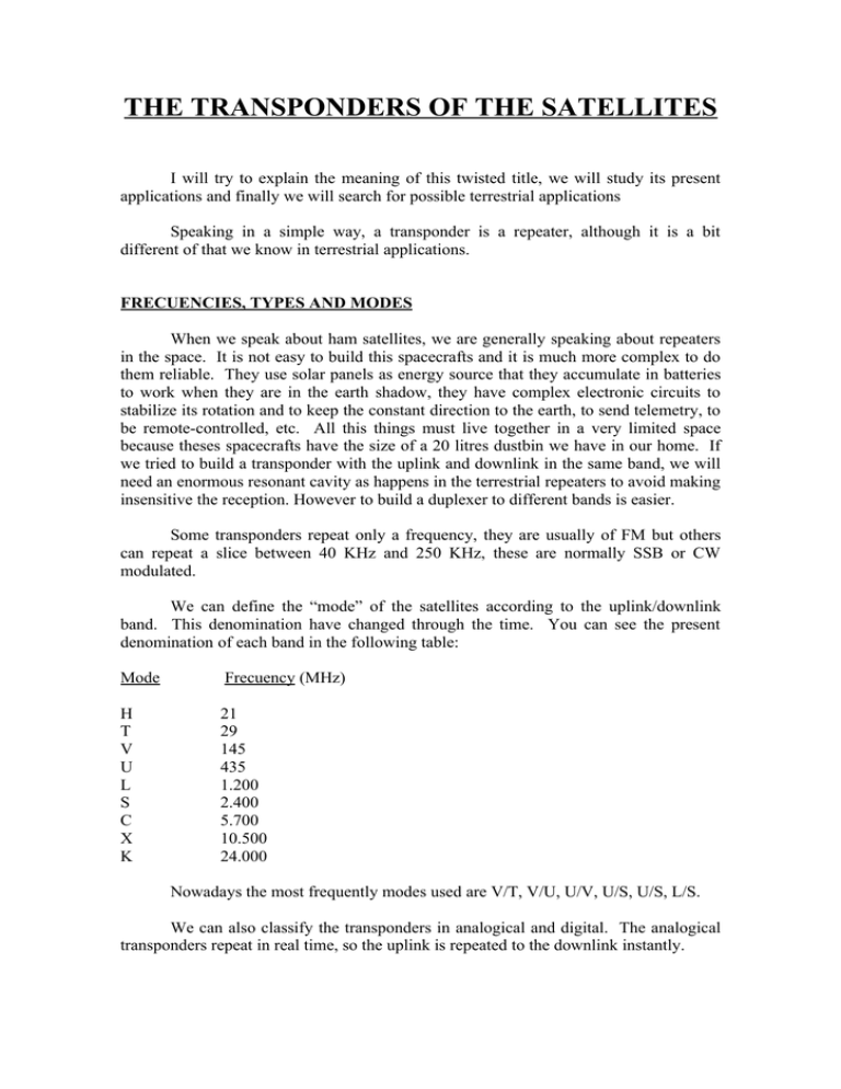
THE TRANSPONDERS OF THE SATELLITES I will try to explain the meaning of this twisted title, we will study its present applications and finally we will search for possible terrestrial applications Speaking in a simple way, a transponder is a repeater, although it is a bit different of that we know in terrestrial applications. FRECUENCIES, TYPES AND MODES When we speak about ham satellites, we are generally speaking about repeaters in the space. It is not easy to build this spacecrafts and it is much more complex to do them reliable. They use solar panels as energy source that they accumulate in batteries to work when they are in the earth shadow, they have complex electronic circuits to stabilize its rotation and to keep the constant direction to the earth, to send telemetry, to be remote-controlled, etc. All this things must live together in a very limited space because theses spacecrafts have the size of a 20 litres dustbin we have in our home. If we tried to build a transponder with the uplink and downlink in the same band, we will need an enormous resonant cavity as happens in the terrestrial repeaters to avoid making insensitive the reception. However to build a duplexer to different bands is easier. Some transponders repeat only a frequency, they are usually of FM but others can repeat a slice between 40 KHz and 250 KHz, these are normally SSB or CW modulated. We can define the “mode” of the satellites according to the uplink/downlink band. This denomination have changed through the time. You can see the present denomination of each band in the following table: Mode Frecuency (MHz) H T V U L S C X K 21 29 145 435 1.200 2.400 5.700 10.500 24.000 Nowadays the most frequently modes used are V/T, V/U, U/V, U/S, U/S, L/S. We can also classify the transponders in analogical and digital. The analogical transponders repeat in real time, so the uplink is repeated to the downlink instantly. However, when the information is received in the digital transponders, it is processed and if it fulfils the requirements then it is modified and repeated later, this is the case of APRS. This kind of transponders usually work in the same band or even in the same frequency, so the terrestrial stations do not need to be full-duplex, only capable to work in split or simplex. Another digital transponders can store information which is repeated when somebody requests it, this is the case of BBS or PACSAT protocols. The PACSAT satellites need two different bands, in the uplink band they receive the requests and information and in the downlink band they send the information requested. In this case the equipment must be full-duplex capable. HOW A TRANSPONDER WORKS The analogical FM one channel and two bands transponders are the most wide spread and its design is similar to a terrestrial repeater. They consist of a receiver and a transmitter, the exchange of information between the uplink and the downlink is made in the audio stage, speaking in a simple way, they work as if the speaker of the receiver was connected to the microphone of the transmitter. Until some years the transponders were transmitting full time, so to save energy some installed a watch, and others do it by means of software, then they transmit only at agreed time or when they are over some latitudes. But recently the SO-50 has incorporated a subtone in the receiver plus a watch, so when the satellite receives this subtone the transponder is opened over 10 minutes after which it is turned off until it receives a new subtone. Diagram nº1: Block diagram of a linear transponder The digital transponders usually take advantage of the FM wide, so we can use our equipment without modifications between 1.200 Bd and 9.600 Bd. Some transponders have been built capable of up to 56.000 Bd so they can exchange information with high speed terrestrial stations. They are used to exchange photos, videos or enormous files. As you can imagine the exchange of information into the satellite between the RX and TX is made after proper wideband filters and software processed before being retransmitted. But in my opinion, the star is the analogical linear transponder. A linear transponder receives a slice of frequencies of a band and the entire slice is retransmitted to a different band. These kind of transponders are very complex electronically. Hams value them highly, although they are difficult to use, because it can support several QSOs at the same time. So I will try to go more deeply into them, I will give as an example the FO-29 which has an inverted linear transponder in V/U mode: - Uplink: Downlink: 145.900 – 146.000 LSB. Central frequency: 145.950 435.800 – 435.900 USB. Central frequency: 435.850 The central frequency will be useful to understand how the Doppler effect works, so I will use it as example. If this effect would not exist, when we uplink in 145.950 MHz we could receive our self in 435.850 MHz. The first thing we must know is that there are direct and inverted linear transponders. To understand how them work we will not take into account the Doppler effect by now. The direct transponders retain the sign. If we uplink in the central frequency plus “X” KHz we will receive the downlink in the central frequency plus “X” KHz. So if we uplink in 145.960 MHz we will downlink in 435.960 MHz. Some books try to explain it by means of a constant “K1” which is the difference between the central frequencies of the both bands, so in a direct linear transponder the equation will be: (1) downlink frequency = K1 + uplink frequency (1) 435.960 = (435.850 – 145.950) + 145.960 The inverted transponders change the sign. If we uplink in the central frequency plus “X” KHz we will receive the downlink in the central frequency minus “X” KHz. So if we uplink in 145.960 MHz we will downlink in 435.940 MHz. In this case the constant “K2” is the sum of the central frequencies of the both bands, so in an inverted linear transponder the equation will be: (2) downlink frequency = K2 - uplink frequency (2) 435.840 = (435.850 + 145.950) - 145.960 It does not mind the rule we use but we must not pay attention to the direct linear transponders because they are just a theory. Actually only are used inverted linear transponders because the Doppler effect is less noticeable as we see later. The Doppler effect will make us life difficult, so we must understand how it works. The Doppler effect is a physical effect and the teachers always explain it with the following example: If we are in a railway station and a train is running at high speed without stopping, if it has its horn blaring in a constant frequency, we will start listening to the horn higher, when the train is in front of us the frequency will not suffer any change and when the train is going away the horn will be lower. The higher the frequency or the speed are the more noticeable the effect will be. In a real case, into the ham bands and taking into account the speed and the distance to the earth of the LEO satellites, the Doppler effect is +/-2.5 KHz in VHF and de +/- 10 KHz in UHF. If a LEO satellite would transmit in 145.950 MHz, and we were in the worst case in which it would pass over our head, when we see it in the horizon we will listen to it in 145.952,5 MHz, when it is over our head in 145.950 MHz and when it is disappearing in 145.987,5 MHz. If the satellite would transmit in 435.850 MHz the effect would be noticeable between 435.860 MHz and 435.840 MHz. When the satellite is in a low far pass, it is moving in relation to us slower than if the satellite is over our head, so the Doppler effect will be less noticeable. It is very important to take into consideration too that the Doppler effect also affects to the satellite reception. To understand all this concepts, I will set an example of a direct and inverted transponder, if we consider the FO-29 satellite frequencies when it is appearing: - Direct transponder: - We transmit in 145.950 - The satellite we will listen to us in 145.952,5 (Doppler Effect) - The satellite will retransmit it in 435.952,5 MHz (see equation (1)) - We will listen the satellite in 435.962,5 MHz (Doppler Effect) - Inverted transponder: - We transmit in 145.950 MHz - The satellite we will listen to us in 145.952,5 MHz (Doppler Effect) - The satellite will retransmit it in 435.947,5 MHz (see equation (2)) - We will listen the satellite in 435.957,5 MHz (Doppler Effect) As we can see in the before example, the inverted transponders reduce the Doppler effect because there is less difference between the uplink and downlink frequencies in relation to the central frequency. So this is the reason why the direct transponders are not used. It is easy to guess that this kind of transponders are very complex because they have to bear a wide band pass, between 40 KHz and 100 KHz in the LEO satellites and up to 250 KHz in the phase 3, such as the AO-40. The exchange between the receiver and the transmitter is not in the audio stage, we must use an intermediate frequency which can bear a wide band pass. Furthermore the system retransmits with proportional power out to the received signal, so the week signals will be repeated weakly and the strong signals strongly. So in the intermediate frequency must be set an AGC circuit (Automatic Gain Control) to limit the strong signals to avoid they take too much power out. For instance, the FO-29 has only 1 Watt to share between all the signals it has to retransmit. And we must take into consideration that the noise and FM undesired signals also take power out. Diagram nº2: AO-07 satellite size To minimize this effect, the band pass can be divided into several sectors, and the power out can be divided into this sectors. So if a strong signal is received in a sector, it will deliver all the power out of this sector, but not all the power out of the transpondedor. This method was only a theory and I think it never took place. The last method designed by AMSAT-DL was named LEILA and it was installed in the AO-40 satellite. It is a complex software set in the 10.7 MHz intermediate frequency which monitors the received signals. When some signal exceeds a pre-established limit then a siren is send, which makes the audio negligible, so the ham must reduce the uplink power out if he wish to be listen to. In the AO-40 I had to reduce my power out down to 10 Watts in 435 MHz a lot of times, to avoid LEILA hunted me. It has been a nice design to avoid the alligators. We can see the typical block diagram of a linear transponder in the diagram nº1, it was set into the AO-07 satellite. We can see the AO-07 size in the diagram nº2. This diagrams have been obtain from the Satellite Handbook published by ARRL. As a curiosity, the AO-07 was launched in 1.981 and it was running over 6 years until its dead, possibly for a shortcut in the batteries. Sixteen years later in July 2.000, Pat Gowen G3IOR listened to the CW beacon. After studying the telemetry they have came to the conclusion that the batteries are open and it is only running with the solar panels. So it only works when it is illuminated, with this precarious conditions I have made incredible contacts with W4MVB Jess, W3JUZ Russell and KB2M Jeff. SOME THOUGHTS As you can see this world is exciting but it needs much effort from all of us to keep the status and to make progress. So the first thing hams must do is to respect the spectrum assigned to satellites in each country, for instance in Spain is: VHF: - 145.200 and 145.800 in FM to spatial communicates with crewed spacecrafts. For example the ISS (International Space Station). - 145.806 - 146.000 all mode to satellite communications exclusively. UHF: - 435.000 - 438.000 all mode to satellite communications, and in second place ATV. SHF: - 1260 - 1270 all mode to satellite communications exclusively. Whatever kind of communications into this portion of the bands which are not in relation to satellites are illegal because they can interfere with satellite communications. Hams must take into account that the signals from the satellites are very weak so the interferences make the communications impossible and if somebody uses these frequencies it is very easy that their modulations were retransmitted into the satellite sole, and in Spain for example, the modulation will be listen in the whole Europe and in the east coast of USA. Last years a lot of people was fined in Mexico because they used these frequencies illegally. The second thing I propose is to respect the radio frequency spectrum assigned to terrestrial transponders, in Spain this portion is: VHF: - 144.630 - 144.660 all modes transponder output. - 144.660 - 144.690 all modes transponder input. UHF: - 432.500 to 432.600 all modes transponder input. - 432.600 to 432.800 all modes transponder output. I do not know if the present regulations let linear transponders between bands, I think it must be possible if not it would not be reasonable that the input and output are so closer in the same band. On the other hand it is worldwide assumed in satellites. I propose to build a direct linear transponder with a bandwidth of 30 KHz, with LSB input in UHF and USB output in VHF or vice versa. It will set in the centre of the Iberian Peninsula in a high place, for example the Madrid mountain. So in a ratio of 300 Km hams could use it as a long path repeater using SSB, CW, PSK31 and RTTY modes. The transmitting antennas could be horizontal polarized and no-directional for 2 meters band, for example an Eggbeater II and 50 Watts. The receiving antennas for 70 cm. band could be six TPM II phased to achieve the 360º taking into account that these antennas have an angle of radiation of 60º. I hope to have explained the topic clearly, at least it was my intention, because the better we understand the transponders work the better we will use the satellites. Juan Antonio Fernández Montaña [email protected] EA4CYQ Note: This article was published in the Unión de Radioaficionados Españoles (URE) monthly magazine in April 2004.
