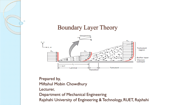
Boundary Layer Theory Prepared by, Miftahul Mobin Chowdhury Lecturer, Department of Mechanical Engineering Rajshahi University of Engineering & Technology, RUET, Rajshahi Why the boundary layer thickness for flow over a flat plate continuously increases? ❑ The momentum of the flat plate is zero and the momentum of the uniform flow has a finite value. When the incoming uniform flow flows over a flat plate, the fluid particles near the plate will stick to the plate (no-slip condition). ❑ That means that the momentum of the flat plate is diffused to the fluid. The reason for this no-slip condition is adhesion between the flat plate and the fluid particles. The fluid particles have a force between them that holds them together, which is cohesion. ❑ When the fluid flows this cohesive force along with adhesion shows itself in the macroscopic scale as viscosity. ❑ As the flow proceeds downstream of the flat plate the viscosity phenomenon prevails and more fluid layers above the flat plate changes it’s momentum. This is what is called momentum transfer. And hence the boundary layer thickness increases as the fluid moves downstream. To plate Drag force on a flat plate due to boundary layer: Von Karman suggested a method based on the momentum equation by the use of which the growth of a boundary layer along a flat plate, the wall shear stress and the drag force could be determined (when the velocity distribution in the boundary layer is known). Starting from the beginning of the plate, the method can be used for both laminar and turbulent boundary layers. The figure below shows a fluid flowing over a thin plate (placed at zero incidence) with a free stream velocity equal to U. Consider a small length dx of the plate at a distance x from the leading edge as shown in the following fig. Consider, a= unit width of plate perpendicular to the direction of flow. Drag force on a flat plate due to boundary layer: (Contd) 𝑑𝑢 𝑑𝑦 𝑑𝑢 𝑑𝑦 The shear stress τ0 is given by, 𝜏0 = 𝜇( )𝑦=0 where, ( )𝑦=0 is the velocity distribution near the plate at y=0. The drag force or shear force on a small distance Δx is given by ΔFdrag = shear stress × Area = 𝜏0 × Δx × (a=1) [ Taking, Δx=dx] = 𝜏0 × dx (i) Let ABCD be a small element of a boundary layer (the edge DC represents the outer edge of the boundary layer). 𝛿 Mass rate of fluid entering through AD = 0 𝜌 × 𝑣𝑒𝑙𝑜𝑐𝑖𝑡𝑦 × 𝐴𝑟𝑒𝑎 𝑜𝑓 𝑠𝑡𝑟𝑖𝑝 𝑜𝑓 𝑡ℎ𝑖𝑐𝑘𝑛𝑒𝑠𝑠 𝑑𝑦 𝛿 = 0 𝜌 × 𝑢 × (𝑎 = 1) × 𝑑𝑦 𝛿 = 0 𝜌𝑢𝑑𝑦 Mass rate of fluid leaving the side BC, Drag force on a flat plate due to boundary layer: (Contd) From continuity equation for a steady incompressible fluid flow, we have𝑚ሶ AD + 𝑚ሶ DC = 𝑚ሶ BC ∴ Mass rate of flow entering AD + Mass rate of flow entering DC = Mass rate of flow leaving side BC ∴ Mass rate of flow entering DC = Mass rate of flow leaving side BC - Mass rate of flow entering AD The fluid is entering through DC with a uniform velocity U. Momentum rate of fluid entering the control volume of X-direction through AD. Momentum rate of fluid leaving the Control Volume in X-direction through BC Momentum rate of fluid entering the control volume through DC in X-direction ∴ Rate of change of momentum of Control Volume = Momentum rate of fluid through BC – Momentum rate of fluid through AD –Momentum of fluid through DC As per momentum principle, the rate of change of momentum on the control volume BCD must be equal to the total force on the control volume in the same direction. Drag force on a flat plate due to boundary layer: (Contd) The only external force acting on the control volume is the share force acting on the side AB in the direction B to in the following figure. The value of this force (drag force) is given by, From the equation (i): ΔFdrag = 𝜏0 × dx Thus the total external force in the direction of the rate of change of momentum ; ΔFdrag = - 𝜏0 × dx (xi) Equating equation (x) and (xi), we have Total external force = Rate of change of momentum (xii) (xiii) This equation is known as von Karman momentum equation for boundary layer flow and it is used to find out the frictional drag on smooth flat plate for both laminar and turbulent boundary layer. The following boundary conditions must be satisfied for any assumed velocity distribution. The sheer stress 𝜏0 for a given velocity profile in laminar, transition or turbulent zone is obtained from equations (xii) and (xiii) above. Then drag force on a small distance dx of a plate is given by Friction Drag: Friction Drag: ❑ The friction drag is proportional to the surface area. Therefore, bodies with a larger surface area will experience a larger friction drag. This is why commercial airplanes reduce their total surface area to save fuel. Friction drag is a strong function of viscosity, and an “idealized” fluid with zero viscosity would produce zero friction drag since the wall shear stress would be zero. ❑ Skin friction is caused by viscous drag in the boundary layer around the object. Basic characteristics of all laminar and turbulent boundary layers are shown in the developing flow over a flat plate. The stages of the formation of the boundary layer are shown in the figure below: ❑ Boundary layers may be either laminar or turbulent, depending on the value of the Reynolds number. The boundary layer is laminar for lower Reynolds numbers, and the streamwise velocity changes uniformly as one moves away from the wall, as shown on the left side of the figure. As the Reynolds number increases (with x), the flow becomes unstable. Finally, the boundary layer is turbulent for higher Reynolds numbers, and the streamwise velocity is characterized by unsteady (changing with time) swirling flows inside the boundary layer. The transition from laminar to turbulent boundary layer occurs when Reynolds number at x exceeds Rex ~ 500,000. The transition may occur earlier, but it is dependent especially on the surface roughness. The turbulent boundary layer thickens more rapidly than the laminar boundary layer due to increased shear stress at the body surface. Skin friction drag ❑ Skin friction drag is a type of aerodynamic drag, which is resistant force exerted on an object moving in a fluid. Skin friction drag is caused by the viscosity of fluids and is developed from laminar drag to turbulent drag as a fluid moves on the surface of an object. ❑ Skin friction drag is generally expressed in terms of the Reynolds number, which is the ratio between inertial force and viscous force. ❑ Total drag can be decomposed into a skin friction drag component and a pressure drag component, where pressure drag includes all other sources of drag including lift-induced drag. ❑ In this conceptualization, lift-induced drag is an artificial abstraction, part of the horizontal component of the aerodynamic reaction force. ❑ Alternatively, total drag can be decomposed into a parasitic drag component and a lift-induced drag component, where parasitic drag is all components of drag except lift-induced drag. In this conceptualization, skin friction drag is a component of parasitic drag. Skin friction drag (Contd) Laminar flow over a body occurs when layers of the fluid move smoothly past each other in parallel lines. In nature, this kind of flow is rare. As the fluid flows over an object, it applies frictional forces to the surface of the object which works to impede forward movement of the object; the result is called skin friction drag. Skin friction drag is often the major component of parasitic drag on objects in a flow. The flow over a body may begin as laminar. As a fluid flows over a surface shear stresses within the fluid slow additional fluid particles causing the boundary layer to grow in thickness. At some point along the flow direction, the flow becomes unstable and becomes turbulent. Turbulent flow has a fluctuating and irregular pattern of flow which is made obvious by the formation of vortices. While the turbulent layer grows, the laminar layer thickness decreases. This results in a thinner laminar boundary layer which, relative to laminar flow, depreciates the magnitude of friction force as fluid flows over the object. Skin-friction Co-efficient: Local co-efficient of drag: It is defined as the ratio of the shear stress 𝜏0 to the quantity ½ ρU2 . It is denoted by C *. Where, D Average Co-efficient of drag: It is defined as the ratio of total drag force to the quantity It is denoted by CD. Where, Parasitic Drag & (Form drag): Parasitic drag: ❖ Parasitic drag, also known as profile drag is a type of aerodynamic drag that acts on any object when the object is moving through a fluid. ❖ Parasitic drag is a combination of form drag, skin friction drag and interference drag. It affects all objects regardless of whether they are capable of generating lift. ❖ Total drag on an aircraft is made up of parasitic drag and lift-induced drag. Parasitic drag comprises all types of drag except lift-induced drag. Form Drag: Form drag arises because of the shape of the object. The general size and shape of the body are the most important factors in form drag; bodies with a larger presented cross-section will have a higher drag than thinner bodies; sleek ("streamlined") objects have lower form drag. Form drag follows the drag equation, meaning that it increases with the square of the velocity, and thus becomes more important for high-speed aircraft. Form drag depends on the longitudinal section of the body. A prudent choice of body profile is essential for a low drag coefficient. Streamlines should be continuous, and separation of the boundary layer with its attendant vortices should be avoided. Interference drag: Form drag includes interference drag, caused by the mixing of airflow streams. For example, where the wing and fuselage meet at the wing root, two airstreams merge into one. This mixing can cause eddy currents, turbulence, or restrict smooth airflow. Interference drag is greater when two surfaces meet at perpendicular angles, and can be minimized by the use of fairings. Wave drag, also known as supersonic wave drag or compressibility drag, is a component of form drag caused by shock waves generated when an aircraft is moving at transonic and supersonic speeds Form drag is a type of pressure drag, a term except lift-induced drag. Form drag is pressure drag due to separation. Lift induced drag: ❑ In aerodynamics, lift-induced drag, induced drag, vortex drag, or sometimes drag due to lift, is an aerodynamic drag force that occurs whenever a moving object redirects the airflow coming at it. ❑ This drag force occurs in airplanes due to wings or a lifting body redirecting air to cause lift and also in cars with airfoil wings that redirect air to cause a downforce. The lift-induced drag coefficient is denoted as CDi . ❑ For a constant amount of lift, induced drag can be reduced by increasing airspeed. A counter-intuitive effect of this is that, up to the speed-for-minimum-drag, aircraft need less power to fly faster. Induced drag is also reduced when the wingspan is higher, or for wings with wingtip devices. ❑ The total aerodynamic force acting on a body is usually thought of as having two components, lift and drag. By definition, the component of force parallel to the oncoming flow is called drag; and the component perpendicular to the oncoming flow is called lift. Lift induced drag: ❑ Induced drag causes wingtip vortices. When producing lift, air below the wing is at a higher pressure than the air pressure above the wing. On a wing of finite span, this pressure difference causes air to flow from the lower surface, around the wingtip, towards the upper surface. This spanwise flow of air combines with chordwise flowing air, which twists the airflow and produces vortices along the wing trailing edge. Induced drag is the cause of the vortices; the vortices do not cause induced drag. ❑ Induced drag is created as a result of lift. As wing passes through the air, an area of lower air pressure is formed on the top of the wing. Higher-pressure air below the wing seeks equilibrium with the lower pressure area above, resulting in a vortex flow from the bottom of the wing to the top. ❑ The flow around the wing tips of a finite wing create an "induced" angle of attack on the wing near the tips. As the angle increases, the lift coefficient increases and this changes the amount of the induced drag. The angle of attack (AOA) is the angle at which the chord of an aircraft's wing meets the relative wind. The chord is a straight line from the leading edge to the trailing edge. In fluid dynamics, a stall is a reduction in the lift coefficient generated by a foil as angle of attack increases. This occurs when the critical angle of attack of the foil is exceeded. The critical angle of attack is typically about 15°, but it may vary significantly depending on the fluid, foil, and Reynolds number. Different types of drag: Parasitic vs lift-induced drag: Math Problem: Velocity distribution: 𝒖 𝝅𝒚 = 𝐬𝐢𝐧( ) 𝑼 𝟐𝜹 Find out the values of 𝛿 (boundary layer thickness), shear stress, 𝐶𝐷∗ local co-efficient of drag, 𝐶𝐷 average co-efficient of drag in terms of Reynolds number, Re ? (i) Boundary layer thickness: 𝝉𝟎 𝒅𝜽 = 𝝆𝑼𝟐 𝒅𝒙 𝒖 𝑺𝒖𝒃𝒔𝒕𝒊𝒕𝒖𝒕𝒊𝒏𝒈 𝒕𝒉𝒆 𝒗𝒂𝒍𝒖𝒆 𝒐𝒇 , 𝒘𝒆 𝒈𝒆𝒕 𝑼 𝛿 𝜏0 𝑑 𝜋𝑦 𝜋𝑦 = න 𝑠𝑖𝑛 1 − 𝑠𝑖𝑛 dy 𝜌𝑈 2 𝑑𝑥 0 2𝛿 2𝛿 𝑑 𝑑𝑥 𝛿 𝜋𝑦 𝜋𝑦 − 𝑠𝑖𝑛2 dy 2𝛿 2𝛿 4−𝜋 𝑑𝛿 𝜏0 = ( )𝜌𝑈 2 (i) 2𝜋 𝑑𝑥 𝒅𝒖 𝝅𝒚 Again, 𝝉𝟎 = 𝝁( )𝒚=𝟎 𝑩𝒖𝒕, 𝒖 = 𝑼 𝐬𝐢𝐧 𝒅𝒚 𝟐𝜹 𝑑𝑢 𝜋𝑦 𝜋 And, = 𝑈[𝑐𝑜𝑠 ( )] × 𝑑𝑦 2𝛿 2𝛿 𝑑𝑢 𝜏0 = 𝜇( )𝑦=0 𝑑𝑦 𝜋0 𝜋 = 𝜇𝑈[cos ( )] × 2𝛿 2𝛿 = 0 𝑠𝑖𝑛 𝜏0 = 𝜇𝑈𝜋 2𝛿 (ii) Math Problem (Contd.): Equating the two values of 𝜏0 given by eqns. (i) & (ii); 4−𝜋 𝑑𝛿 𝜇𝑈𝜋 ( 2𝜋 )𝜌𝑈 2 𝑑𝑥 = 2𝛿 𝜇 𝛿𝑑𝛿 = 11.4975 𝑑𝑥 𝜌𝑈 Integrating both sides, we get 𝛿2 𝜇 = 11.4975 x+C 2 𝜌𝑈 At, x=0, 𝛿=0 Therefore, C=0 𝛿2 𝜇 ∴ 2 = 11.4975 𝜌𝑈 x By simplifying we get, 𝜹 = (ii) Shear Stress: 𝜏0 𝜇𝑈𝜋 2𝛿 4.795𝑥 But, 𝛿 = √𝑅𝑒𝑥 𝜏0 = By simplifying: 𝝁𝑼 𝝉𝟎 = 𝟎. 𝟑𝟐𝟕 𝑹𝒆𝒙 𝒙 𝟒.𝟕𝟗𝟓𝒙 √𝑹𝒆𝒙 Math Problem (Contd.): (iii) Local co-efficient of drag: 𝐶𝐷∗ 𝜏0 = 0.327 𝜇𝑈 𝑥 𝑅𝑒𝑥 And, we know that, 𝜌𝑈 2 ∗ 𝜏0 = 𝐶𝐷 × 2 By equating these two equations we get, 𝟎.𝟔𝟓𝟒 𝑪∗𝑫 = 𝑹𝒆𝒙 (iv) 𝐶𝐷 average co-efficient of drag: (iii) We know that, 𝐿 (iv) Where, 𝐹𝐷 = 0 𝜏0 × 𝐵 × 𝑑𝑥 𝐿 = 0 0.327 𝜇𝑈 𝑥 = 0.327 × 2𝜇𝑈 𝑅𝑒𝑥 × 𝐵 × 𝑑𝑥 𝜌𝑈 ×𝐵× 𝜇 𝐿 ∴ 𝑭𝑫 = 𝟎. 𝟔𝟓𝟒 𝝆𝑼𝑳 𝝁 Math Problem (Contd.): Now, putting the value of 𝑭𝑫 in the equation We get, 0.654𝜇𝑈𝐵 𝐶𝐷 = 𝜌𝑈𝐿 𝜇 1 𝜌𝐴𝑈 2 2 Here, 𝐴 = 𝐿 × 𝐵 By simplifying we get, 𝐶𝐷 = 1.31 × ∴ 𝑪𝑫 = 1 𝜌𝑈𝐿 𝜇 𝟏.𝟑𝟏 √𝑹𝒆𝑳 Values of 𝛿, 𝐶𝐷∗ and 𝐶𝐷 𝑖𝑛 𝑡𝑒𝑟𝑚𝑠 𝑜𝑓 𝑅𝑒: The below table shows the values of 𝛿 (boundary layer thickness), 𝐶𝐷∗ local co-efficient of drag, 𝐶𝐷 average co-efficient of drag in terms of Reynolds number for various velocity distribution: Values of 𝛿, 𝐶𝐷∗ and 𝐶𝐷 𝑖𝑛 𝑡𝑒𝑟𝑚𝑠 𝑜𝑓 𝑅𝑒: SI. No. 1 2 3 4 5 𝑢 𝑦 =2 𝑈 𝛿 𝑦 𝛿 − ( )2 𝑢 3 𝑦 1 𝑦 = − ( )3 𝑈 2 𝛿 2 𝛿 𝑢 𝑦 𝑦 𝑦 =2 − 2( )3 + ( )4 𝑈 𝛿 𝛿 𝛿 𝑢 𝜋𝑦 = sin( ) 𝑈 2𝛿 Blasius results (𝑅𝑒 < 3.2 × 10⁵ 𝛿 𝐶𝐷∗ 𝐶𝐷 5.48𝑥 0.73𝑥 1.46 √𝑅𝑒𝑥 4.64𝑥 √𝑅𝑒𝑥 0.646𝑥 √𝑅𝑒𝐿 1.292 √𝑅𝑒𝑥 5.84𝑥 √𝑅𝑒𝑥 0.686 √𝑅𝑒𝐿 1.372 √𝑅𝑒𝑥 4.795𝑥 √𝑅𝑒𝑥 0.654 √𝑅𝑒𝐿 1.31 √𝑅𝑒𝑥 5𝑥 √𝑅𝑒𝑥 0.664 √𝑅𝑒𝐿 1.328 √𝑅𝑒𝑥 √𝑅𝑒𝑥 √𝑅𝑒𝐿 Turbulent boundary layer: In comparison to laminar boundary layers, the turbulent boundary layers are thicker. In a turbulent boundary layer, the velocity distribution is much more uniform, than in a laminar boundary layer, due to intermingling of fluid particles between different layers of the fluid. The velocity distribution in a turbulent boundary layer follows a logarithmic law i.e, u~logy, which can also be represented by a power law of the type, 𝒖 𝒚 = ( )𝒏 𝑼 𝜹 7 5 Where, n=1/7 (approx.) for 𝑅𝑒 < 10 𝑏𝑢𝑡 > 5 × 10 𝒖 𝒚 𝟏 = ( )𝟕 𝑼 𝜹 This is known as the one-seventh power law. This equation cannot be applied at the boundary itself because at y=0 1 6 𝛿𝑢 1 = 𝑈𝛿 −7 𝑦 −7 =∝ 𝛿𝑦 7 This difficulty is circumvented by considering the velocity in the viscous laminar sub layer to be linear and tangential to the seventh-root profile at the point, where the laminar sublayer merges with the turbulent part of the boundary layer. For Reynolds number between 𝟏𝟎𝟕 𝒂𝒏𝒅 𝟏𝟎𝟗 𝒕𝒉𝒆 𝒓𝒆𝒍𝒂𝒕𝒊𝒐𝒏𝒔𝒉𝒊𝒑 𝒃𝒆𝒕𝒘𝒆𝒆𝒏 𝑪𝑫 and Re is suggested by Prandtl as: 𝑪𝑫 = 𝟎. 𝟒𝟓𝟓 (𝐥𝐨𝐠 𝟏𝟎 𝑹𝒆𝑳 )𝟐.𝟓𝟖 Home work: Find out the values of 𝛿 (boundary layer thickness), shear stress, 𝐶𝐷∗ local co-efficient of drag, 𝐶𝐷 average co𝒖 𝒚 efficient of drag in terms of Reynolds number, Re of the equation = ( )𝒏 ? 𝑼 𝜹 Total drag due to laminar and turbulent boundary layers: When the leading edge is not very rough, the turbulent boundary layer does not begin at the leading edge, it is usually preceded by the laminar boundary layer. The point of transition from laminar to turbulent layer depends upon the intensity of turbulence. The distance 𝑥𝑐 of the transition from leading edge can be obtained from critical Reynolds number which normally ranges from 3 × 10⁵ 𝑡𝑜 3 × 10⁶ . Drag force 𝐹𝐷 =F for the turbulent boundary layer can be estimated from the following relation: 𝐹𝑡𝑢𝑟𝑏. = (𝐹𝑡𝑢𝑟𝑏 )𝑡𝑜𝑡𝑎𝑙 − (𝐹𝑡𝑢𝑟𝑏 )𝑥𝑐 Where, (𝐹𝑡𝑢𝑟𝑏 )𝑡𝑜𝑡𝑎𝑙 = The drag which would occur if a turbulent boundary extends along the entire length of the plate, and (𝐹𝑡𝑢𝑟𝑏 )𝑥𝑐 = The drag due to fictious turbulent boundary layer from the leading edge to a distance 𝑥𝑐 . ∴ 𝐹𝑡𝑜𝑡𝑎𝑙 = 𝐹𝑙𝑎𝑚𝑖𝑛𝑎𝑟 + 𝐹𝑡𝑢𝑟𝑏𝑢𝑙𝑒𝑛𝑡 Math Problems: Q.A Find the skin friction drag on one side of the plate 199 mm wide 499 mm long placed longitudinally in a stream of crude oil (specific gravity = 0.925, kinematic viscosity = 0.9 stokes) flowing with an undisturbed velocity of 5 m/s. Also, find the thickness of the boundary layer and the shear stress at the trailing edge of the plate. Q.B For the velocity profile in laminar boundary layer as, 𝑢 3 𝑦 = 𝑈 2 𝛿 1 𝑦 2 𝛿 − ( )3 Find the thickness of the boundary layer and the shear stress 1.5 m from the leading edge of a plate. The plate is 2 m long and 1.5 m wide and is placed in water which is moving with a velocity of 200 mm per second. If dynamic viscosity for water is 0.01 poise – Determine, the total boundary friction drag on the plate. Math Problems: Q.C A flat plate dimensions are 5.4𝑚 × 2.66𝑚. Air is flowing over the plate with 4.11 m/s velocity at 180 𝐶. Calculate, (i) The length of plate over which the boundary layer is laminar. (ii) Thickness of laminar boundary layer. (iii) Shear stress at the location where the boundary layer ceases to be laminar. (iv) Total friction drag on both sides on that portion of plate where boundary layer is laminar. 2 𝑘𝑔 −5 𝑚 Take, 𝜌 = 1.21 3 𝑎𝑛𝑑 𝜗 = 1.471 × 10 . 𝑚 𝑠 Math problems: Q.D Air is flowing over a smooth flat plate with a velocity of 10 m/s. The velocity profile is given by 𝑢 𝑦 =2 𝑈 𝛿 𝑦 𝛿 𝑦 𝛿 − 2( )3 + ( )4 The plate dimensions are 1.2m ×0.91m. If laminar 105 and kinematic viscosity of air = 0.15 stokes. Find, boundary layer exists upto a value of Re = 2 × (i) The maximum distance from the leading edge upto which laminar boundary layer exists. (ii) The maximum thickness of the boundary layer. Q.E A passenger ship of cylindrical shape has rounded nose. If the length and diameter of the ship are 49.8m and 4.98m, determine the total power required for overcoming the boundary friction. The ship cruises at 7.99 m/s velocity in sea water at 190 𝐶. Take, 𝜌 = 1028𝑘𝑔 𝑎𝑛𝑑 kinematic viscosity is 1.19 × 10⁻⁶ 𝑚2 /𝑠 𝑚3 Math Problems: Q.F A 2m wide and 4.9 m long plate when towed through water at 200 𝐶 experiences a drag of 30.30 N on both the sides. 𝜇 = 10−3 𝑁𝑠/𝑚2 . Determine, (i) The velocity of the plate (ii) The length over which the boundary layer is laminar. Concept of flow separation: ❖ A boundary layer exists whenever there is relative movement between a fluid and a solid surface with viscous forces present in the layer of fluid close to the surface. The flow can be externally, around a body, or internally, in an enclosed passage. ❖ Boundary layers can be either laminar or turbulent. A reasonable assessment of whether the boundary layer will be laminar or turbulent can be made by calculating the Reynolds number of the local flow conditions. Separation occurs in flow that is slowing down, with pressure increasing, after passing the thickest part of a streamline body or passing through a widening passage, for example. ❑ Flowing against an increasing pressure is known as flowing in an adverse pressure gradient. ❑ The boundary layer separates when it has travelled far enough in an adverse pressure gradient that the speed of the boundary layer relative to the surface has stopped and reversed direction. ❑ The flow becomes detached from the surface, and instead takes the forms of eddies and vortices. ❑ The fluid exerts a constant pressure on the surface once it has separated instead of a continually increasing pressure if still attached. In aerodynamics, flow separation results in reduced lift and increased pressure drag, caused by the pressure differential between the front and rear surfaces of the object. It causes buffeting of aircraft structures and control surfaces. In internal passages separation causes stalling and vibrations in machinery blading and increased losses(lower efficiency) in inlets and compressors. What is boundary layer flow separation? ❑ In fluid dynamics, flow separation or boundary layer separation is the detachment of a boundary layer from a surface into a wake. ❑ Flow separation occurs when the boundary layer travels far enough against an adverse pressure gradient that the speed of the boundary layer relative to the object falls almost to zero. ❑ The fluid flow becomes detached from the surface of the object, and instead takes the forms of eddies and vortices. ❑ The boundary layer separation increases drag on the body. ❑ Separation takes place due to excessive momentum loss near the wall in a boundary layer trying to move downstream against increasing pressure, i.e which is called adverse pressure gradient. In a flowing fluid when a solid body is immersed, a thin layer of fluid called the boundary layer is formed adjacent to the solid body. The forces acting on the fluid in the boundary layer are; (i) Inertia forces (ii) Viscous forces and, (iii) Pressure forces Boundary layer tripping ➢ Boundary layer tripping is a means of adding energy to the boundary layer by scooping some flow from the free-stream and injecting it into the boundary layer. ➢ The injected flow is invariably turbulent so the boundary layer becomes turbulent. The turbulent boundary layer causes greater skin friction drag than a laminar boundary layer, but the turbulent boundary layer will stay attached to the surface longer and thereby provide a net reduction in drag. ➢ On older commercial airliners (e.g. Boeing 727) vortex generators were used extensively on the upper surface of the wing to trip the boundary layer and keep the flow attached to a point further back on the wing, thus reducing drag, especially at cruise speeds. ➢ On newer aircraft computational fluid dynamics techniques have been used to precisely define wing shapes to avoid the need for boundary layer tripping. Boundary layer flow separation Boundary layer flow separation (Contd.): Boundary layer flow separation (Contd.): Boundary layer flow separation (Contd.): Flow separation point: ❑ Near the point where the solid boundary begins to diverge or fall away from the direction of the mean flow, the boundary layer separates or breaks away from the boundary. ❑ The separation point is the point where the air stops "sticking" to an object that is moving through the air. When an object is moving through the air, the air molecules push back on it and resist the object's movement - this resistance is called pressure drag. ❑ The separation point is defined as a location between forward and inverse flow where the wall shear stress is zero. ‐ The thickness of the boundary layer abruptly increases at the separation point, and the layer is forced off the surface by the reversed flow near the wall. 𝑑𝑢 ( )𝑦=0 = 0, 𝑆𝑒𝑝𝑎𝑟𝑡𝑖𝑜𝑛 𝑜𝑓 𝑓𝑙𝑜𝑤 𝑑𝑦 Flow Separation control: Flow Separation control: Contd.


