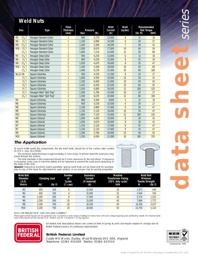
Size M5 – (3/16”) M6 – (1/4”) M8 – (5/16”) M10 – (3/8”) (7/16”) M5 – (3/16”) M6 – (1/4”) M8 – (5/16”) M10 – (3/8”) (7/16”) No.12 UN (1/4”) (3/8”) (3/8”) (1/2”) (1/4”) (7/16”) M5 M6 M8 M8 M12 M6 M6 M7 M7 M8 M10 Plate Thickness (mm) Type Hexagon Standard Collar Hexagon Standard Collar Hexagon Standard Collar Hexagon Standard Collar Hexagon Standard Collar Hexagon Deep Collar Hexagon Deep Collar Hexagon Deep Collar Hexagon Deep Collar Hexagon Deep Collar Square Collarless Square Collarless Square Collarless Square Collarless Square Collarless Hexagon Weld “Split Trap” Hexagon Weld “Split Trap” Square Collarless Square Collarless Square Collarless Square Collarless Square Collarless Square Collared Square Collared Square Collared Square Collared Square Collared Square Collared 1 1 1 1 1 2 2 2 2 2 1 1 1 2 2 1 2 1 1 1 2 2 1 2 1 2 2 2 Pressure (lbs) (N) Weld Current (A) Weld (cycles) 960 1,100 1,200 1,500 1,600 950 950 1,050 1,200 1,400 950 1,000 1,350 1,425 1,550 1,300 1,500 800 950 1,100 1,150 1,600 1,000 1,050 1,150 1,150 1,300 1,350 13,000 14,500 16,500 17,000 22,000 13,000 15,000 16,000 18,000 21,000 11,500 16,000 21,000 22,500 26,500 14,500 20,000 9,000 10,500 17,000 18,000 24,000 19,000 18,000 17,000 17,000 19,000 21,000 6 6 7 10 12 6 8 8 10 10 9 10 10 10 12 10 12 5 6 9 10 12 8 9 8 9 10 10 4,270 4,890 5,340 6,670 7,210 4,230 4,230 4,670 5,340 6,230 4,220 4,450 6,000 6,430 6,900 5,780 6,670 3,560 4,230 4,890 5,120 7,120 4,450 4,670 5,120 5,120 5,780 6,000 Recommended Test Torque (lb/ft) (NM) 12 20 30 40 50 12 25 35 50 80 20 30 40 60 100 20 80 12 20 35 35 100 30 30 35 35 40 100 16 27 41 54 68 16 34 47 68 108 27 41 54 81 135 27 108 16 27 47 47 135 41 41 47 47 54 135 The Application To avoid brittle welds the components, like the weld bolts, should be of low carbon steel content (0.15% C max. B.S.2996). The minimum sheet thickness is approximately 0.7mm (22g). In thinner sheet the weld pool may break through the surface. The hole diameter in the component should be 0.5mm clearance for the bolt shank. If clearance is excessive, extra care in machine setting will be required to prevent the weld pools spreading to the edge of the hole. Special: Subjects to economic batch quantities, special weld bolts can be made with for example, pips on top of the head for attachment to outer surface, or an annular ring for sealing properties. Weld Bolt Diameter I.S.O. Metric (N) M3 M4 M5 M6 M8 M10 450 450 1,300 2,200 3,100 3,100 (lb/f) Number of Cycles (1/50 sec) Secondary Current (if metered) (A) Machine Transformer Rating (50% duty cycle) kVA 100 100 300 500 700 700 4 4 8 10 10 10 12,000 15,000 17,000 15,000 16,500 18,000 10 15 20 40 40 50 Clamping Load Weld Bolt Minimum Tensile Strength N (lb/f) 1,973 3,444 5,570 7,884 14,356 22,750 444 744 1,252 1,772 3,227 5,114 data sheet series Weld Nuts FOR 3 PIP PROJECTION, USE 50% LESS CURRENT These approximate figures are for guidance only. In practice a wide range of settings of clamp load, time and voltage tappings give satisfactory results. For Imperial bolts read of the figures for the nearest I.S.O. Meteric size (N = Newtons = 0.1kg approx). All details and descriptions shown are correct at time of going to print, but maybe subject to change due to British Federal’s policy of continuous improvement British Federal Limited Castle Mill Works, Dudley, West Midlands DY1 4DA, England Telephone: 01384 455400 Telefax: 01384 455554 Certificate No. 2088 Printed in England 06/96 M51670 Trinity Design Consultants (0121) 321 2321
