12 G to 20 G compact rectangle waveguide to circular waveguide mode convertor
Anuncio
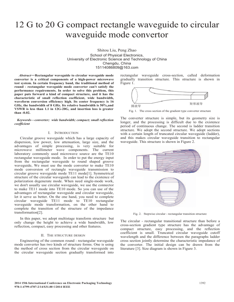
12 G to 20 G compact rectangle waveguide to circular waveguide mode convertor Shitou Liu, Peng Zhao School of Physical Electronics, University of Electronic Science and Technology of China Chengdu, China [email protected] Abstract— — Rectangular waveguide to circular waveguide mode converter is a critical components of a high-power microwave test system. In certain frequency band, the traditional method of round - rectangular waveguide mode converter can't satisfy the performance requirements. In order to solve this problem, this paper puts forward a kind of compact structure, and it has the characteristic of small reflection coefficient, wide bandwidth, waveform conversion efficiency high. Its center frequency is 16 GHz, the bandwidth of 8 GHz. Its relative bandwidth is 50%,and VSWR is less than 1.1 in 12G-20G, and insertion loss is greater than -0.02. Keywords—converter; wide bandwidth; compact; small reflection coefficient I. INTRODUCTION Circular groove waveguide which has a large capacity of dispersion, low power, low attenuation, large size, and the advantages of simple processing, is very suitable for microwave millimeter wave components. The current laboratory commonly used microwave source are the TE10 rectangular waveguide mode. In order to put the energy input from the rectangular waveguide to round shaped groove waveguide, We must use the mode converter to make TE10 mode conversion of rectangle waveguide transmission to circular groove waveguide mode TE11 mode[1]. Symmetrical structure of the circular waveguide can lead to the existence of polarization degenerate mode. When need single-mode work, we don't usually use circular waveguide, we use the connector to make TE11 mode into TE10 mode. So you can use of the advantages of rectangular waveguide and circular waveguide, let it serve us better. On the one hand, you need to complete circular waveguide TE11 mode to TE10 rectangular waveguide mode transformation, on the other hand to complete the transition of the structure of the impedance transformation[2]. In this paper, we adopt multistage transform structure but only change the height to achieve a wide bandwidth, low reflection, compact, easy processing and other features. II. THE STRUCTURE DESIGN Engineering of the common round - rectangular waveguide mode converter has two kinds of structure forms. One is using the method of cross section from the circular waveguide on the circular waveguide section gradually transformed into WK,QWHUQDWLRQDO&RQIHUHQFHRQ(OHFWURQLF3DFNDJLQJ7HFKQRORJ\ 978-1-4799-4707-2/14/$31.00 ©2014 IEEE rectangular waveguide cross-section, called deformation gradually transition structure. This structure is shown in Figure 1. Fig. 1. The cross section of the gradient type converter structure The converter structure is simple, but its geometry size is longer, and the processing is difficult due to the existence period of continuous change. The second is ladder transition structure. We adopt the second structure. We adopt sections with a certain length of truncated circular waveguide (ladder), and this makes circular waveguide transition to rectangular waveguide. This structure is shown in Figure 2. Fig. 2. Stepwise circular - rectangular transition structure The circular - rectangular transitional structure than before a cross-section gradient type structure has the advantage of compact structure, easy processing, and the reflection coefficient is small. Truncated circular waveguide cutoff wavelength and the difference between the paragraphs ladder cross section jointly determine the characteristic impedance of the converter. The initial design can be drawn from the literature [3]. Size diagram is shown in Figure 3. 1392 $a1% L1 $a2% L2 Fig. 4. S11 $a3% L3 L4 $a4% $a% Fig. 5. S21 & b ( & b4 ( & b3 ( & b2 ( & b1 ( & 2R ( Fig. 3. Size marking figure According to the actual requirements, the center frequency is 16 G, absolute bandwidth is 8 G, and within the band VSWR is less than 1.1. VSWR is closer to 1, the higher transmission efficiency. According to the theory, matching section length is approximately a quarter wavelength, that is L1=L2=L3=L4 4.7mm. The difference between the width is about 1 mm, that is (bi bi 1 ) / 2 1mm . This design according to some actual requirements, a is 15.8 mm, b=7.9mm(bj140), R=7.9mm. The figure 4 shows that S11 is less than -37 dB form 12.4G to 20G and S11 is less than -30 dB form 12G to 12.4G. VSWR is less than 1.1 is equivalent to S11 is less than -26 dB. Therefore, our simulation results is far superior to the design requirements. S21 is close to zero. We found that the optimized L is larger than the initial value. This is due to the changes brought by the ladder capacitance. The actual value of bi basically accord with the theoretical value. IV. CONCLUSION Due to the actual needs of bandwidth are wide, reflection coefficient is small, we chose the ladder transition structure. Through theoretical calculation and software simulation optimization, we finally got a waveguide mode converter whose center frequency is 16 G, absolute bandwidth is 8 G VSWR is less than 1.1 The results show that the design method is feasible. III. THE SIMULATION AND ANALYSIS According to the initial size, we use the 3D simulation software u-wave modeling. Through the optimized variables LI and Bi , the simulation results meet the design requirements. The optimized values of each parameter is as follows:L1=7.19mm,L2=6.44mm,L3=5.72mm,L4=4.95mm,b1 =14.29mm,b2=12.51mm,b3=10.07mm,b4=8.28mm. Reflection and transmission curve as are shown in the Figure4 and Figure5 below. Acknowledgment This work was supported by 702 office. The authors would like to thank the Liu Chen for helping this work. References [1] [2] [3] WK,QWHUQDWLRQDO&RQIHUHQFHRQ(OHFWURQLF3DFNDJLQJ7HFKQRORJ\ CHEN Dong2dong,SUN Yong2zhi,NIUBin,YANG Hong2sheng. Optimized Design of Rectangle Waveguide to Circular Waveguide Mode Convertor[J]. Chinese Journal of Electron Devices.Vol.29 No.2 Jun.2006:410-412. LiSimin, ZHENG Keke, CAO Weiping. Study of improved circular waveguide to rectangle waveguide mode convertor[J].ELECTRONIC COMPONENTS AND MATERIALS. Vol.32 No.6 Jun.2013:61-64. Luokun Liu, Guangxiang Sun.Round - Rectangular Transition Design[J]. Electronic scientific journal. Vol.14 No.16 Nov.1992:657-660. 1393
