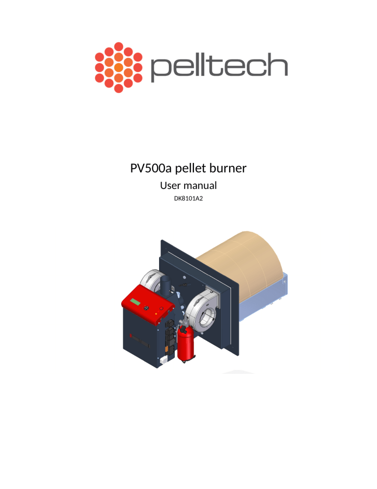
PV500a pellet burner User manual DK8101A2 PV500a pellet burner p 2/36 Table of Contents Tables................................................................................................................................................3 Safety precautions.............................................................................................................................4 Warnings...........................................................................................................................................4 Notice................................................................................................................................................4 1 Set of components..........................................................................................................................6 2 General description........................................................................................................................7 2.1 Safety devices......................................................................................................................10 2.2 Pellets...................................................................................................................................10 3 Installation...................................................................................................................................11 3.1 Prerequisites.........................................................................................................................11 3.2 Burner installation................................................................................................................13 3.3 Powder extinguishing system..............................................................................................15 3.4 External auger......................................................................................................................15 3.5 Pellet storage........................................................................................................................16 3.6 Electrical connections..........................................................................................................16 3.7 External inverters.................................................................................................................17 3.8 Internet module....................................................................................................................17 3.9 Initial start-up.......................................................................................................................17 4 Optional components...................................................................................................................18 4.1 Error output..........................................................................................................................18 4.2 Flue gas fan..........................................................................................................................18 Burner setup...............................................................................................................................19 Inverter setup.............................................................................................................................19 4.3 Oxygen sensor......................................................................................................................20 4.4 Ash removal system.............................................................................................................20 4.5 External boiler temperature sensor (TMP1 or X23)............................................................21 4.6 External boiler pressure sensor (TMP1 or X23)..................................................................22 5 Operation and service..................................................................................................................23 5.1 User interface.......................................................................................................................23 5.2 Starting and stopping...........................................................................................................24 5.3 Fuel refilling.........................................................................................................................24 5.4 Status and parameters..........................................................................................................24 5.5 Regular maintenance............................................................................................................32 6 Annex 1 Electrical connections...................................................................................................33 6.1 Fuses....................................................................................................................................35 7 Warranty.......................................................................................................................................35 PV500a pellet burner p 3/36 Tables Table 1 Technical data of burner.................................................................................................................. 7 Table 2 List of main components................................................................................................................. 9 Table 3 Pellets' key data............................................................................................................................. 10 Table 4 Measurements of openings.......................................................................................................... 11 Table 5 Connectors..................................................................................................................................... 16 Table 6 PAR50 values................................................................................................................................. 18 Table 7 PAR66 and PAR67 set-up...............................................................................................................20 Table 8 Summary of burner statuses......................................................................................................... 25 Table 9 List of tests in TESTING status....................................................................................................... 26 Table 10 CLEANING parameters................................................................................................................. 26 Table 11 LOADING parameters and timing............................................................................................27 Table 12 IGNITION parameters and timing................................................................................................ 27 Table 13 PRE-BURN parameters................................................................................................................ 28 Table 14 HEAT UP parameters................................................................................................................... 28 Table 15 HOLD FLAME parameters............................................................................................................30 Table 16 END BURN parameters................................................................................................................31 Table 17 END BLOW parameters................................................................................................................ 31 PV500a pellet burner p 4/36 Safety precautions Do not start the burner before it is connected to the boiler and the boiler is connected to the chimney. It is recommended to wear a respirator while handling pellets. The boiler room where the burner is installed must fulfil all rules and recommendations given by authorities. All electrical connections must be done by trained professionals. No flammable materials must be stored near the burner. Warnings Changing the construction of the burner without written permission from the manufacturer is forbidden. Use only spare parts provided or approved by the manufacturer in order to avoid any damage to the burner and dangers resulting from it. Welding is allowed only after disconnecting the burner from electric supply. The circuit board must be removed from the burner. Do not open any boiler door while the burner is in operation. Notice Manufacturer of burner has right to make changes in construction of burner and its firmware. Burner corresponds to following directives and standards: Directive 2004/108/EC Directive 2006/95/EC Directive 2001/95/EC Directive 2006/42/EC EN 15270 2008 EN 230 2005 EN 60370-2-5 2002 Pellet burner PV 500a No Year of production 2019 Electrical supply 230V Max heat input 560kW Emission class 5 Noise emission 52dB Power consumption at standby 7 W Manufacturer: Pelltech OÜ, Sära tee 3, Peetri, Estonia PV500a pellet burner p 5/36 PV500a pellet burner 1 p 6/36 Set of components 1 3 1. Burner with burning chamber 2. Bracket 2 pcs 3. Hose 76mm PV500a pellet burner 2 p 7/36 General description PV500a is a burner of wooden pellets (sawdust granules) that is intended for heating of the industrial and public buildings. Only 6 or 8mm wooden pellets can be used to run this burner. You cannot use any other form of fuel. Unique design of the burning chamber allows using industrial pellets run the burner. The construction allows burner to be used with different boilers: liquid fuel, solid fuel and universal boilers. The burner is connected to the boiler by using a connection plate. The burner is equipped with a melting hose, extinguishing system and auxiliary battery for protection against back-burning. Main technical data is gicen in Table 1 and Figure 1. Table 1 Technical data of burner Size Unit Value L total length L1 housing length L2 burning chamber length ⌀D1 internal feeder’s tube diameter H1 total height H2 burning chamber height W1 burner housing width W2 burning chamber width Mass(neto) Maximum fuel consumption Maximum amount of fluegases(200ºC) Nominal power Minimal power Noise level Emission class (EN 15279) Operating temperature Supply voltage Electrical power at ignition Average electrical power Electrical power at standby mm mm mm mm mm mm mm mm kg Kg/h M3/h kW kW dB o C VAC W W W 1203 595 600 80 395 457 606 528 165 104 1400 500 160 58 5 0 - 60 400V – 3 f 800 50 – 80 7 Figure 1 Main measurements of burner PV500a pellet burner p 8/36 Figure 2 Main components of burner PV500a pellet burner Nr 1 2 3 4 5 Name Back wall fire brick Arc fire bricks 6pcs Side fire bricks 4pcs Burning chamber Grates 2+3pcs 6 7 Igniter 2pcs Internal feeder spiral 8 Secondary fan 9 Feeder motors 10 11 12 13 14 15 16 17 Burner’s socket User interface User interface screen Air box Fixating flange Flame sensor Powder extinguishing system Fuel level sensor 18 Internet module 19 Backup battery 2pcs 20 21 22 Linear motor Controller board Primary fan 23 Burners input tube Table 2 List of main components p 9/36 Description To cover back side of burning chamber. To cover the top of burning chamber. To cover the sides of burning chamber. Place of gasification and burning of pellets. Moving grates to remove ash from the burning chamber. 2 grates with smaller hole are placed before 3 grates with bigger holes. Electrical heating element to ignite pellets. Transports pellets to the burning chamber. The feeder is connected to feeder motor with little slack. It prolongs motor and feeder lifetime. Do not over tighten the feeder connection. Blows burning air into burning chamber according to burner’s actual power. Rotates internal feed screws. The feeder is connected to feeder motor with little slack in order to avoid the auger get stuck. To internal and external electrical connections. Enable to navigate in burner menus and change parameter values. 4-row LCD screen to move in menus, set up and change parameter values. To control air input and fixate burner to boiler’s door. To adapt fixation of burning chamber to boiler’s door. Optical sensor (photocell) to detect flame in burning chamber. To fast extinguishing of fire in feeder’s tube. Optical sensor, which signal starts external auger. Sensor consists of sender – receiver pair. Gives possibility to observe and control the functioning of the burner over the internet. Enables to complete the burning procedure if mains supply lost. It is a safety measure against back-burning and takes approx. 30min. Moves grates in order to remove ash from burning chamber. Controls the functioning of the burner. Blows burning air into burning chamber according to burner’s actual power. To be connected via hose with external auger. Supplies burner with pellets. PV500a pellet burner 2.1 p 10/36 Safety devices The back-burning is the biggest danger risk at burners working procedure. Back-burning appears when usual pressure or draught conditions have changed in boiler’s combustion chamber. There are several reasons for such changes. In order to secure operational and fire safety the burner PV500a is equipped with following safety devices: Back up batteries. Enable to safely empty the pellets inside the burners internal tube into the burning chamber in case of unexpected power outage. Melting hose. The external auger is connected to the burner with a special hose (Ø 76mm), which is made from easily melding polyurethane material that interrupts when back-burning takes place. Such measurement avoids entrance of the flame from the burner into external auger and pellets Powder extinguishing system. Enables to extinguish the fire inside the burner internal tube by filling it with extinguishing powder when the burner has overheated or burned back due to some fault. 2.2 Pellets Wooden pellets or saw dust granules are concentrated and homogenized wooden fuel made from sawdust and cutter shavings. Pellets are pressed with high temperature. No extra materials are added, pellets are held together by a natural ingredient found in wood – lignin. Pellets are neutral, renewable fuel. Its burning doesn’t spoil CO2 balance in the atmosphere. Not only premium but also the industrial pellets can be used in PV500a. Pellets must be stored in a dry and ventilated room. Some key data for industrial and premium wooden pellets are given in Table 3. Premium pellets Industrial pellets Raw material Stem wood, wood processing industry residues + whole trees, bark, logging residues Calorific value Volume wight Volume of 1 ton pellet Diameter Length Moisture content Ash content To replace 1000 l light oil 4700-5100 kWh/ton ca 650-670 kg/m3 1.5-1.6 m3 6-10 mm 3-5 x diameeter 8-10 % ca 0,5% ca 2 tons or 3 m3 ca 4700 kWh/ton >675 kg/ m3 ca 1.5 m3 6-12 mm ca 4mm ca 5 % ca 2% ca 2 tons or 3 m3 Table 3 Pellets’ key data PV500a pellet burner 3 3.1 p 11/36 Installation Prerequisites In order to install the burner, the boiler must meet the following requirements: It is recommended to use three pass boilers. The construction of the boiler must make it possible to open the door of the boiler with the burner connected and removing ash from the furnace. If the door of the boiler is too narrow for opening it together with the burner, then extra hinges must be mounted. The boiler must be positioned in a way that there is enough space for cleaning the burner, the boiler, the smoke pipe and removing the ash. The burning chamber must not touch the bottom of the boilers furnace (min 10cm distance needed). To ensure negative pressure in the furnace, a flue gas fan should be installed. Boiler room must provide constant air supply of 500 m³ per hour (ca. 400 cm2 air inlet opening). The boiler room where the burner is installed must fulfil all rules and recommendations given by local authorities. In order to install the burner to the boiler door, there must be mounting holes as shown below. Note: If the burner is installed to the boiler, the door or the installation flange´s thickness should be 814mm. Dimension ⌀D hole for burning chamber neck ⌀D1 flange bolt ring diameter ⌀D2 bolt holes Bolt hole offset angle Angle between bolt holes Table 4 Measurements of openings Figure 3 Boiler door mounting opening when standing in front of the boiler Unit Value mm mm mm deg deg 355 400 13 15 60 PV500a pellet burner p 12/36 Boiler firebox depth L (Figure 4) must be at least 3,5 times longer than the burner’s burning chamber. The minimal length of the firebox L has to be 2200 mm. The height of firebox must leave at least 100 mm (H1) for ash below burning chamber. Figure 4 Firebox depth Minimum dimensions: L1 ≥700mm H ≥700mm Pellet burners need regular cleaning and therefore boiler construction must allow easy opening of boiler’s door without removing the burner. The minimum size of opening in boiler’s door depends on the position of door hinges. Figure 5 below illustrates the situation. Point C is critical point. In order to keep door width minimum and boiler’s door opening small, a double hinge solution can be used. As double hinges add another degree of moving-freedom, door must be fastened on both sides. Slide-out doors with guide rails is also an option. Figure 5 Burner has to come off from boiler Double hinges PV500a pellet burner 3.2 p 13/36 Burner installation NR.1 Connect the flange with M12 bolts to the boilers door. Bolt length should be chosen according to the doors thickness. NR.2 Connect burning chamber to the flange with M12x50 bolts and M12x40 long nuts as shown on the picture. Figure 6 NR.3 Attach the outer part of the burner to the flange with five M12x70 bolts. Figure 7 PV500a pellet burner p 14/36 Check igniters positioning in the burning chamber. Igniters ends have to be in same level with their holders housings (Figure 8). Igniters have not to be in direct touch with flame or pellets. If so, igniters will burn out quite quickly Figure 8 Figure 9 Place the grates back to the burning chamber starting from the lower ones and working upwards. Keep in mind to put the small and larger grate in steps between each level, so that the common side of the grates won’t align between levels. Last level of grates have to be mounted on it’s holder, slided into position and fixed from behind with M10 butterfly nuts (Figure 10). Finally install the bricks by starting with the back wall bricks, next install the side bricks and finish the assembly with the arc bricks. Figure 10 PV500a pellet burner 3.3 p 15/36 Powder extinguishing system All PV500a burners are equiped with powder extinguishing system. System is autonomous and only requires removing the safety latch. NB! Before activating the system please read the user manual. Activating the system before reading the manual is forbiden and could result in an accidental opening of the extinguisher !!! 3.4 External auger The external auger transports pellets from the pellet container to the burner. The auger is controlled by burner. The auger is connected to the burner with a special hose (∅ 76mm), which is made from easily melting polyurethane material that melts when back-burning takes place. The hose acts as a safety measure against back-burning. PV500a pellet burner´s fuel consumption at full power is about 97 - 107 kg of pellets per hour (1,65 kg per minute ). External auger´s productivity must be at least 200kg of pellets per hour. The auger can be fixed to the storage or a ceiling depending on the conditions at the installation site. Requirements for auger installation: • The raising angle of the external auger must not exceed 45°. • The end of the exit tube of the auger and the input of the burner must not be aligned. The recommended minimal horizontal distance is 20cm. • The distance between the input of the burner and the exit tube of the external auger must be at least 60cm vertically – recommended distance is 80-200cm. • Hose between auger and burner must be strait and stressed and not be bended through, otherwise pellets may block the auger and interrupt burner’s normal work. Falling angle must me between 65° and 85°. All critical requirements to installation of external auger are depicted in Figure 11. >20cm >65 o max45 o Figure 11 External auger installation >60cm PV500a pellet burner 3.5 p 16/36 Pellet storage Pellets must be stored in a dry and ventilated room that is separated from the boiler room. A tailor made silo for particular storage is recommended. All safety regulation must be taken into consideration according to the local laws. It is recommended to wear a respirator when handling pellets. Refilling must be carried out before the storage runs empty. 3.6 Electrical connections Following connections must be done by the electrical installer: 1-phase supply and boiler’s thermostat to socket X11. 3-phase supply to socket X12 External auger to socket X14 Burner gets its main supply from 230V single phase supply (socket X11), but also needs 400V 3-phase to socket X12 to run inverters and augers. Boiler should be equipped with thermostat or external switch what has to be connected to pins T1 and T2 in 7- pole plug X11 for turning on/off the pellet burner. Auger motors contactors are equipped with motor thermal protection, which prevent motor from overheating. As soon as the nominal current of the sensor set-point is exceeded, the relay detects this variation and the output relay cuts off the power to the motor. Burner can be equipped with optional lambda sensor. It provides efficient control for optimal performance concentrating emissions and burning efficiency. Marking Description Color Data X11 Power input Black/Brown 230V 16A X12 Power input Black 3x400V 4A X13 Safety circuit White X14 External auger 1 Black 0,55kW 1,6A X15 External auger 2 Black 0,55kW 1,6A X16 Secondary fan White 0,15kW 0,65A X17 Süütepulgad Black 2x500W 2,2A X20 External inverter Brown X21 Fluegas fan White X22 Modbus Brown X23 Lambda probe/temperature sensor Green X24 Silo sensors Green X25 Ash removal 2x1-phase White X26 Primary fan White 0,15kW 0,65A X29 Ash removal 3-phase Black 0,55kW 1,6A X30 UPS input Black Table 5 Connectors 3x240V 0,75kW max 4A PV500a pellet burner 3.7 p 17/36 External inverters Flue gas fan can be controlled by external inverter. Following configuration must be made: • • Inverter must use 0-10V speed signal. “Forward” command must use sink logic (0V signal starts fan). Before connecting the external inverter pleas look into the connection diagram. 3.8 Internet module Every PV500a burner has an internet module in standard equipment. It is located next to the burner controller under the red cover. The module itself is connected to the MOD1 connector, located on the controller. For the internet module to work, it has to be connected to the internet with a CAT5 cable. To observe and control the burner, you have to login in to the page: „cloud.pelltech.eu”. Login data can be found on the module. To get more info about the internet module, please read the instruction manual or contact your local reseller. 3.9 Initial start-up Prior to the initial start-up of the burner make sure that: • • • • • • The burner is connected to the boiler. The boiler thermostat is installed and functioning properly. The external auger of the burner is installed and connected to the burner. The smoke duct is connected to the chimney, the dampers for smoke gases are open and there is sufficient draught. When the burner is operating, the negative pressure inside the furnace must stay between 5-20 Pa. Powder extinguishing system is activated. (Please read the instruction manual!!!). Phase (L) and neutral (N) wires in power cable are connected properly. PV500a pellet burner 4 4.1 p 18/36 Optional components Error output PV500a burner has built in error output what gives 230 VAC tension (NO) to 7-pole socket’s S3 connector or interrupts it (NC) if burner delivers any error message (E16 FLAME, E48 BATTERY,E24 IGNITION etc). Device (motor, modem etc) up to 5A@230VAC can be connected to this output. PAR50 defines wether error output is closed or open during error appearance. PAR50 value 1 2 Description Normaly open. Will switch on contacts in case of error. Normaly closed. Will switch off contacts in case of error. Table 6 PAR50 values 4.2 Flue gas fan The burner needs stable under-pressure in burning chamber for its correct operation. Simplest way to assure this is to use the flue gas fan between boiler and chimney. With flue gas fan the burner can control and hold constant under-pressure. In order to control flue gas the PAR60 value has to be set to”2” Inverter. Selected flue gas fan must provide transmission of the maximum flue gas amount and exceed the pressure provided by boiler, ash cyclone and chimney. The flue gas capacity for burned pellets can be calculated by simplified formula. V – Capacity range in m³/h P – Burner max power in kW Tfg – Flue gas absolute temperature in K Troom - Room absolute temperature in K λ (lambda) – Excess air ratio PV burners are designed to work at lambda values 1.2...1.5 - for calculations choose value of 1.5. Flue gas fan must be installed between boiler and chimney. If ash cyclone is used then flue gas fan must be installed between ash cyclone and chimney to avoid overpressure in cyclone and smoke leakage. PV500a pellet burner p 19/36 Burner setup Depending on burner’s configuration (weather inverter included or not) the electrical connections may be different. In case the frequency inverter has already been installed in factory to the burner, the flue gas fan can be directly connected to the burner through connector X21. Fan must be connected to burner with 3-wire cable (3x1. 5mm²). Internal inverter output is 3 x 240V. Flue gas fan motor has to be connected as delta. In case the burner is ordered without Flue gas inverter, the external inverter for flue gas fan can be used. Inverter must be selected according to fan motor’s parameters and available power supply. The inverter must be switched to sink logic (negative common). To connect the external inverter with burner there is connector X20 with 3 output signals: • • • T1 - burner DC common (ground), must be connected with external inverter input common. S3 – inverters “run” command, must be connected with F (forward) pin on inverter input. Burner will connect this pin to ground when fan must run. B4 – 0… 10V output for fan speed, must be connected with inverter analog input. Inverter setup Inverter parameters are set up at factory for automatic control. To test flue gas fan manually: 1. Press Easy button on inverter 2. Press dial button and change settings : a. CN0D “0” b. FN0D “0” c. F127 “0” PV500a pellet burner 4.3 p 20/36 Oxygen sensor To use the oxygen sensor for measuring the oxygen levels in the flue gases, two parameters have to be adjusted in the parameters menu: PAR66 and PAR67. Parameter Nr Description Unit Name Value Def Min Max PAR66 OXYGEN TYPE 0 – No sensor 1 – 4…20mA = 0…25% oxygen value 2 – 4…20mA = 0…20% oxygen value 3 – Oxygen value from boiler controller - 0 0 3 PAR67 OXYGEN SET Oxygen value setpoint % 5,6 3,0 10,0 Table 7 PAR66 and PAR67 set-up For lambda sensor EP0006, the PAR66 value has to be set to “1”. Some third party oxygen amount sensors use 4…20mA output for 0…20% oxygen. In this case, value “2” must be selected. If PAR66 is set to “0” (no sensor), secondary fan is driven by air table set in PAR31 – PAR36. Secondary fan also switches back to air table if oxygen level reading is below 1.5% or over 19%. Oxygen sensor should be placed into smoke tubing after the boiler. Placement has to be chosen so that the turbulance of the gases is minimal in that place. That means that it isn’t recommended to place the sensor after tight turns or other measuring equipment. Oxygen level can be seen in INFO-menu next to pressure reading. The value on the screen must be divided by 10 to get the real value. For example “O2=113” means oxygen level value 11.3%. 4.4 Ash removal system The burner is capable to control boilers ash removal auger and scrapes. To do that burner has a 3phase or a 1 phase output connectors where you can connect the ash removal system motors. Connector X29 has one motor 3 phase output and X25 is able to control two 1 phase motors. PV500a pellet burner 4.5 p 21/36 External boiler temperature sensor (TMP1 or X23) External temperature sensor enables the burner to maintain constant boiler’s water temperature. For that external temperature sensor has to be installed to relevant place on boiler and external sensor to be connected to connector TMP1 or X23. In parameters menu PAR53 value has to be chosen “1”. When temperature holding status is activated, then burner will change its power according to water temperature and speed of temperature changing. Burner starts to change its power when BURNING status has lasted longer than set in PAR15. Power is changed according to next parameters: PAR 17 defines the time between power raises, PAR 18 defines the time between power lowering. Following actions must be done to enable temperature hold mode (THM): 1. Mount external temperature sensor to boiler according to boiler manufacturer instructions. 2. Connect the sensor to TMP1 or X23 connector.. 3. Choose PAR53 value (sensor type) according to sensor type. Type table can be found in software manual. 4. Set requested temperature – PAR54. It should be lower than boiler thermostat temperature. Otherwise the boiler thermostat would force the burner to turn off before reaching PAR54 value. 5. Optionally PAR55 - the hysteresis of requested temperature can be changed. THM activates if PAR53 value is larger than “0” and BURNING status has lasted longer than set in PAR15 (typically 30min). The burner will change its output power according to current measured temperature and the rate of temperature change. Temperature sensor could be PT100, sensor with mA output or a sensor provided by the burner manufacturer. Different sensors need different hardware that can be selected with JP1 and JP2. Configuration for sensors is as followed: PT100 PV500a pellet burner p 22/36 Pelltech’s sensor from TMP1 Sensor with mA output 4.6 External boiler pressure sensor (TMP1 or X23) External pressure sensor enables the burner to maintain constant pressure in boiler. For that external pressure sensor has to be installed to relevant place on boiler and external sensor to be connected to connector TMP1 or X23. In parameters menu PAR53 value has to be chosen larger than “1o”. When pressure holding status is activated, then burner will change its power according to boiler pressure and speed of pressure changing. Burner starts to change its power when BURNING status has lasted longer than set in PAR15. Power is changed according to next parameters: PAR 17 defines the time between power raises, PAR 18 defines the time between power lowering. Following actions must be done to enable pressure hold mode (PHM): 1. Mount external temperature sensor to boiler according to boiler manufacturer instructions. 2. Connect the sensor to TMP1 or X23 connector. 3. Choose PAR53 value (sensor type) according to sensor type. Type table can be found in software manual. 4. Set requested pressure – PAR54. It should be lower than boiler pressure switch level, otherwise the boiler pressure switch would force the burner to turn off before reaching PAR54 value. 5. Optionally PAR55 - the hysteresis of requested pressure can be changed. PHM activates if PAR53 value is larger than “10” and BURNING status has lasted longer than set in PAR15 (typically 30min). The burner will change its output power according to current measured pressure and the rate of pressure change. PV500a pellet burner 5 5.1 p 23/36 Operation and service User interface The burner is controlled by user interface on the front panel. LCD screen (1) displays settings menu, event log and actual statuses of the burner. Yellow LED (2) shows the presence of flame in burning chamber. In case it blinks, the burner is out of normal operation. Green LED (6) indicates existence of fuel in the burner. To move in menus, use up and down (↑↓) buttons, to change parameter, press OK, to go back to STATUS menu press left button. On Figure 12 are described additional parts on the burner cover. 1. 4-row LCD display. 2. Yellow LED, indicates presence of flame in the burning chamber. 3. Buttons 4. Orange burner operation light, indicates delivery of the signal from the boiler’s thermostat. Red light indicates that safety circuit is opened. 5. Red burner on/off switch can be used to turned the Burners working command on/off. 6. Green LED, indicates existence of the fuel in the burner. 7. Internet module cable (if module used). Figure 12 User interface PV500a pellet burner 5.2 p 24/36 Starting and stopping To turn on the burner, turn on the boiler main switch. If burner displays STOPPED, then go to main menu and change parameter BURNER from OFF to ON. The display shows WAITING. Now turn boiler thermostat to desired temperature. The burner will go to TESTING, then CLEANING and then to LOADING-state. If this is the first run, external auger needs to fill up with pellets. It may take as long as 20minutes. To stop the burner, set BURNER from ON to OFF in main menu. Now the burner will burn all pellets in burning chamber and turn safely to standby. STATUS menu displays the changes: BURNING → END BURN → END BLOW → STOPPED The stopping procedure may take up to 30 minutes. Attention! If necessary, the burners working command can be switched from ON to OFF with the switch on the burner cover. Caution! Do not turn off mains power to terminate burning process. Use the boilers thermostat for that. In order to complete burning procedure safely let the burner to burn all fuel in burning chamber. Never leave burner unattended when you had to stop boilers work by switching off main power. 5.3 Fuel refilling Fuel container has to be refilled before its runs out. The fuel can be added any time to container. If container runs out before refilling, refill it and restart the burner. The start-up takes now longer about 20 minutes, because external auger has to be filled with pellets like on initial start-up. Turn burner from BURNER menu ON. Vice versa the “E04 PELLETS” error is displayed, because loading time is exceeded. 5.4 Status and parameters PV500a pellet burner operates in many different states, which are called “Status”. Log screen STATUS menu displays last and actual events (burner statuses) and their duration. Burner changes its statuses based on received input signals from sensors and values set by user. The statuses in typical working order of cycles are given in Table 8. The duration of all actions are in form mm:ss (’m’ in the middle) or hh:mm (’h’ in the middle) or dd:hh (‘d’ in the middle). For example: ’IGNITING 01m25“means the burner ignition state lasted 1 minute and 25 second. Lower row of the log shows burner’s current state. To reach the lower row, press the “down”(↓) button, until you reach the lower row with current state. The duration of current state updates every second or every minute. Changed data blinks. PV500a pellet burner p 25/36 Status Short description WAITING Waiting when boiler’s thermostat switches on. TESTING Boiler’s thermostat is switched on, testing the battery, fans, feeder and draught in progress. CLEANING Ash removing from burning chamber. LOADING Loading pellets with auger into burner and by feeder into burning chamber. IGNITING Igniter is turned on, pellets are ignited. PRE-BURN Flame is recognized, small amount of pellets are added by feeder auger. HEAT UP Burning chamber ceramic stones are heated slowly up. BURNING Normal burning operation. SLOW DOWN Burner is slowly dropping it’s power. HOLD FLAME Thermostat is switched off, small flame is held alive. END BURN Thermostat is switched off, feeder is burned up. END BLOW Pellet coals in burning chamber are burnt, flame has disappeared. WAITING Burner waits when boiler’s thermostat switches on.. Table 8 Summary of burner statuses At WAITING status, the burner waits for boiler’s thermostat switching on. There is no time limit for WAITING status. Only feeder auger is working periodically at WAITING status and makes works for one second after every 2 minutes. With this feeder augers spiral cleans feeder’s tube from wastes. When boilers thermostat switches on, burner will go to TESTING. At TESTING status, burner‘s integrity and important device functioning are checked. List of tests is given in Table 9 . PV500a pellet burner PAR Nr PAR name p 26/36 Test name Test conditions - Battery voltage Battery charging is turned OFF and feeder auger is turned ON. Battery voltage must be greater than 23,63V. - Draft Draft ΔPa >40Pa , when comparing draft before and after testing. PAR69 OXYGEN TEST Oxygen value testing Oxygen value must be higher than PAR69 value. väärtus PAR3 FAN@ Primary fan speed Primary fan speed must be higher than PAR3 – 2. PAR3 FAN@ Secondary fan speed Secondary fan speed must be higher than PAR3 – 2. Table 9 List of tests in TESTING status At CLEANING status, the linear motor (actuator) moves the grates and pushes the ash and residues out of burning chamber. The CLEANING cycle might be divided into 2 steps: 1. Grates are pulled fully into the burning chamber’s burner side. 2. Grates are pushed fully out to end of boiler’s side. 3. Grate are pulled into the starting position PAR Nr PAR name Value Unit PAR description PAR49 CLEANING TIME 1…14 sek Grate movement outwards must last longer than defined in this parameter, if it last shorter, the cleaning cycle is repeated. PAR48 CLEANING CYCLE 0...250 min Time between two cleaning cycles. If this time is doubled, the burner will make an emergency cleaning, otherwise the cleaning takes place at next startup. PAR47 GRATES CURRENT 0.2..6 A Maximum current that the linears can draw from the power supply. If this level is exceeded, the cleaning cycle will be started again. Table 10 CLEANING parameters At the LOADING status, external auger is turned on. When pellet level in the burner reaches to level sensors, feeder auger is started. Feeder auger loads necessary amount of fuel needed for ignition into burning chamber. Anount of fuel loaded is measured by counting the feeders working time. LOADING cycle will end when feeder has worked the time defined in PAR24. PV500a pellet burner PAR Nr. Parameter name PAR24 p 27/36 Default value Unit Comment LOADING FEED 35 sec Needed feeder working time to load pellets into burning chamber. Depends on burner model. PAR25 LOADING 2 FEED 5 sec Feeder working time in second loading. - Max loading time 5 min Feeder auger’s maximum regular loading time. - First loading time after manual start. 20 min Feeder auger’s maximum loading time after manual start or error. - Auger start 2,5 sec Auger start delay if no fuel in burner. PAR82 AUGER OFF 2,5 sec Auger stop delay if fuel in burner. - Feeder start 1 sec Feeder start delay when fuel in burner. - Feeder stop 8 sec Feeder working time without pellets before stoping. Table 11 LOADING parameters and timing In LOADING state the auger holds permanent fuel level in burner pellet inlet. Depengin on the level sensors signal, the auger is switched on and off. Feeder’s work also depends on level sensors. Maximum loading time is limited to 20 minutes after first start or error, because long auger systems need some time to fill up. In next loadings, maximum time is limited to 5 minutes. If maximum loading time is exceeded and silo selection function is used, the burner will switch loading over to the second auger. In single silo system, error E04 PELLETS is displayed. At IGNITING cycle the igniter is heated up and fan blows hot air on pellets in burning chamber. Hot air ignites pellets. Igniter is working periodically at ignition time in order to avoid its overheating. Igniter is pre-heated already in the end of loading cycle, 20 seconds before the loading feed end. If the igniter has been turned on for more than 1 minute at loading time, the it will be turned off. Par Nr. Parameter name Default value Unit PAR8 FAN@IGNITING 20 rps Primary fan speed at ignition. PAR39 FAN2 MIN 7 rps Secondary fan speed at ignition. PAR85 IGNITION TIME 60 % Igniter power at ignition. - Maks. süütamise aeg 254 sec Maximum ignition time. Table 12 IGNITION parameters and timing Comment PV500a pellet burner p 28/36 The purpose of PRE-BURN status is to create stable flame and assure effective pellets burning procedure after ignition. Minimum fuel amount is added periodically at pre-burn time. Fans are working with same speed as at IGNITION. Par Nr. Parameter name Default value Unit PAR8 FAN@IGNITING 20 rps Primary fan speed in PRE-BURN. PAR39 FAN 2 MIN 7 rps Secondary fan speed in PRE-BURN. PAR41 PRE-BURN 25 sec Length between fuel addings. PAR42 PRE-BURN CYCLES 6 x Fuel addings in PRE-BURN state. 1 sec Feeder work time in each cycle. - Comment Table 13 PRE-BURN parameters HEAT UP cycle is needed to slow down heating up of the burning chamber’s ceramic stones in order to minimize their thermal stress and thus prolong their lifetime. PAR Nr. Parameter name Default value Unit Comment PAR70 HEAT UP TIME 20 min Initial heat up time of ceramic stones. PAR71 HEAT UP POWER 40 kW Initial heat up power of ceramic stones. PAR72 HEAT UP TEMP 500 ⁰C Ceramic stones heat up setpoint. Table 14 HEAT UP parameters When HEAT UP is in mode ON - burner stops HEAT UP cycle after heat up time set in PAR70 is exceeded. When HEAT UP is in AUTO mode - burner stops HEAT UP cycle after time set in PAR70 is exceeded or stone temperature is higher than set in PAR72. BURNING is main action status in burner’s every day’s operation. Burner can operate on 11 different fixed power levels. There are 6 main power levels, which can be selected and adjusted. 5 virtual power levels (between main power levels) are for smoother operation – they can't be adjusted or selected. For every power level, the primary fan speed is fixed in PAR1...PAR6 and secondary fan speed in PAR31...PAR36. The fan speed for virtual levels is calculated as average from previous and next main level speed 7 6 5 4 3 2 1 p 29/36 level Power PV500a pellet burner Power level can be selected in main menu. Power level selection for burning time can be automatic or fixed on some main level. When power level is fixed, the power is slowly raised to selected level and will be there until boiler thermostat switches off. Selected power Par 17 Burning time 2 2 2 min Figure 13 Burning at fixed power Power level In Automatic Power mode (POWER = AUTO in main menu), the operation power is selected automatically depending on burning cycle length. 9 8 7 6 5 4 3 2 1 Max power (par 14) OFF Thermostat ON New operation power Operation power Par 15 Par 15 Par 17 2 2 2 „Burning“ 30 “Testing“ „Loading“ „Igniting“ “End burn“ „Pre-burn“ „End Blow“ „Waiting“ 30 Figure 14 Burning procedure when power selection = AUTO Par 15 „Burning“ Time(min) PV500a pellet burner p 30/36 level Power In SLOW DOWN mode, the burner power is reduced step-by-step to 1 level after boiler thermostat is switched OFF. This mode can be used only in systems with high and stable power demand. Using SLOW DOWN mode in systems with low thermal inertia or unstable power demand, there will be risk of system overheating. The SLOW DOWN mode is recommended to use together with HOLD FLAME. “SLOW DOWN” mode can be switched ON or OFF from main menu. 7 6 5 4 3 2 1 Thermostat ON Thermostat OFF Operation power Par 17 Par 18 „Burn end“ „Burning“ „Slow down“ „Burning“ „Slow down“ OR „Hold flame“ Status/time Figure 15 SLOW DOWN mode The purpose of HOLD FLAME mode is to avoid burner start-up procedures i.e TESTING, CLEANING, LOADING, IGNITING etc. every time, when burner is switched on from boiler thermostat. In HOLD FLAME mode, minimum fuel and air amount are delivered to burning chamber. HOLD FLAME mode can be switched on from burner main menu. When HOLD FLAME is set to AUTO, burner will turn the mode ON or OFF depending on WAITING time: If WAITING (time between END BLOW and boiler thermostat switched on) is shorter than set in PAR 11, then HOLD FLAME mode will be switched on. If HOLD FLAME time is longer than set in PAR12, HOLD FLAME mode is switched off. HOLD FLAME is also used as intermediate state before CLEANING or after SLOW DOWN. PAR Nr Parameter name PAR10 FAN@HOLD FLAME 10 rps Primary fan speed in HOLD FLAME state. PAR39 FAN 2 MIN 7 rps Secondary fan speed in HOLD FLAME state. PAR11 HOLD FLAME ON 15 min If waiting state has been shorter, HOLD FLAME will be switched on. PAR12 HOLD FLAME OFF 60 min Maximum time when burner holds flame. Table 15 HOLD FLAME parameters Default value Unit Comment PV500a pellet burner p 31/36 The END BURN cycle helps securely to stop burning procedure in burning chamber of burner. All pellets inside the burning chamber and feeder tubes will be burnt. Amounts of pellets delivered and fan rotation speed (power level) are same as in BURNING status. If burner goes to END BURN from other states (e. g. HOLD FLAME), the first power level is selected. Burner works in END BURN until feeder tube is empty feeder has worked as long as described in PAR26. PAR Nr Parameter name Default value Unit Comment PAR26 END BURN FEED 65 sek Feeder working time to clean up feeder’s pipe. - Minimum feed 20 sek If feeder has worked for less time and thermostat is switched on, then burner will switch back to BURNING. Table 16 END BURN parameters The END BLOW cycle is needed to burn finally all unburned pellet coals in the burning chamber. Burner will wait for flame disappearing in burning chamber. In PAR27 is fixed the end blow time, i.e. the time how long the fans continue to blow after flame’s disappearing. PAR Nr Parameter name Default value Unit PAR9 FAN@END BURN 20 rps Primary fan speed in END BLOW. PAR39 FAN 2 MIN 7 rps Secondary fan speed in END BLOW. PAR27 END BLOW TIME 2 min Time to blow air after flame has dissapeared. - Max. END BLOW time 20 min Maximum time when flame has to dissapear in END BLOW state. Table 17 END BLOW parameters Comment PV500a pellet burner 5.5 p 32/36 Regular maintenance The burning chamber of pellet burner PV500a is equipped with automatic self-cleaning and ash removing systems. When system works regularly, there is no need to clean the burning chamber separately. Still the corners and edges of the burning chamber should be monitored for ash and other deposits. If needed cleaning must be done. Only the boiler needs regular cleaning and maintenance. Despite burner has selfcleaning ash removing system, nevertheless the ash collects under and on grates. That’s why at least twice a heating period the grates need cleaning. The frequency of maintenance depends on quality of pellets and intensity of heating. To clean the burning chamber: 1. Turn the burner off by switching from main menu BURNER to OFF. 2. Let the burner cool down for at least one hour. 3. Open boilers door, to enter to burning chamber. 4. Remove upper arc fire bricks. 5. Remove grates and clean them totally up. Make sure that all holes in grate were clean. 6. Place back grates. Make sure the grate to be placed correctly to holders. 7. To end the cleaning, shut the boiler’s door and turn thermostat ot requiered temeperature and turn burner ON. Despite burner has self-cleaning system the boiler has to be cleaned from collected ash and nonburning residues. Manufacturer of pellet burners don’t prescribe time period between cleaning. The ash and non-burning residues are perfect heat insulators. If burning chamber is surrounded with ash and non-burning residues so its normal ventilation is distracted. It causes fast overheating, outburning and deformation of the burning chamber. ATTENTION! BOILER HAS TO BE CLEANED FROM ASH AND NON-BURNING RESIDUES BEFORE THEY GET IN TOUCH WITH BURNERS BURNING CHAMBER. ATTENTION! DEFORMATION AND OUT-BURNING OF BURNING CHAMBER CAUSED BY CLEANING MADE NOT IN TIME IS NOT MANUFACTURING DEFECT AND WILL NOT BE COVERED BY WARRANTY. PV500a pellet burner 6 p 33/36 Annex 1 Electrical connections PV500a pellet burner p 34/36 PV500a pellet burner 6.1 Fuses Fuse F4 F6 F10 F20 F21 F22 F23 F24 F25 7 p 35/36 Size 6A 6A 2A 1A 1A 1A 1A 2A 2A Device 24V DC power supply Battery Linear motor Ash removal auger 1 Ash removal auger 2 Error relay and PSU Cooling fans Secondary fan Primary fan Warranty Warranty objects in this context are pellet burner PV500a and supplied auger. Producer gives 2 years warranty from the date of sale for the PV500a burner and supplied auger. Warranty is valid when user had not made changes in the construction and setup of the burner. Warranty does not cover defects caused by an accident, misuse, abuse, improper installation or operation, lack of reasonable care, unauthorized medication, loss of parts, tampering, attempted repair by a not authorized person, mains errors or using poor quality fuel. Warranty is valid only if the installers memorandum is filled in and sent or brought to the office of Pelltech OÜ Sära tee 3, Peetri, Rae vald, 75312 Harjumaa ESTONIA Ph.. + 372 677 5277 www.pelltech.ee [email protected] Installers memorandum Burner serial number: Serial number, mark and modification Internet module: Cable or Wi-Fi, serial number Boiler mark: Manufacturer, mark, serial number System type: Central heating, steam, dryer, etc. Fluegas fan: Manufacturer, power, serial number Fluegas fan inverter: Internal External Type, size Ash cyclon: Yes No Type, size External auger(s): Mark, tube length, power, pitch angle Pellet silo: Mark, size, distance from boiler Boiler room: Dimensions, material Chimney: Material, flue diameter, height, draught in Pa with cold chimney Air inlet hatch: Dimensions, location(outer wall, inner wall, door) Remarks: Boiler installation specialities and remarks Client: Name/ Aaddress / Phone/ e-mail Installation date: Installer: Name / Company name / Phone/ e-mail/ Signature Installation protocol must be filled in web at cloud.pelltech.eu or on paper. Photo of the filled form must be sent to [email protected] . Without photo or filled form in internet, the warranty is void.
