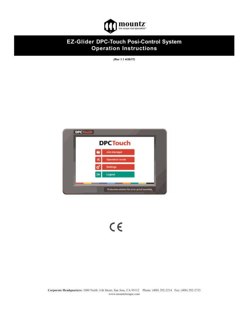
EZ-Glider DPC-Touch Posi-Control System Operation Instructions (Rev 1.1 4/26/17) Corporate Headquarters: 1080 North 11th Street, San Jose, CA 95112 Phone: (408) 292-2214 Fax: (408) 292-2733 www.mountztorque.com Heading Page Hardware Interface Ports Getting Started & Main Menu Job Manager New Job Creation Settings Operating Mode Electrical Wire 3 4 5 6 7 13 19 20 S P E C I F I C AT I O N S 1. Input power: DC24V, 1AAC 100-240V / DC 24V adapter is provided. 2. Dimensions: 202(W) x 128(H) x 38(D) mm 3. Weight 1.2 lbs. 4. Screen: 7” LCD Touch screen, 800 x 480 px 5. Graphical interface: Visualization of assembly process with graphical instructions 6. Inputs and Outputs 24V: 12 inputs and 12 outputs with assignable functions.Logical I/OF for workstation automation 7. Analog encoders: 4 channels, 0...5V 8. Memory card: Removable SD card, 8Gb 9. Total jobs memory: 255 jobs with open structure 10. Total positions memory: 255 jobs x 255 steps x 99 positions per fastening step max 100 steps of the same type in one job 11. Positioning accuracy: 0.09° for angular encoders <0.5 mm for linear encoders 12. Positioning tolerance: Adjustable for each position and for each axis. Smart tolerance detection feature. 13. Compatible tools: All tool with signals – electric or pneumatic. Min required signals: «Fastening OK», «Tool Lock» 14. Communication: RS232 for bar code scanner and firmware upgrade Page 2 Corporate Headquarters: 1080 North 11th Street, San Jose, CA 95112 Phone: (408) 292-2214 Fax: (408) 292-2733 www.mountztorque.com HARDWARE Dimensions and Mounting Interface Mounting plate with 4 x M3 screws is delivered with the controller as a standard accessory. Weight of the controller: 1.2 lbs. Page 3 Corporate Headquarters: 1080 North 11th Street, San Jose, CA 95112 Phone: (408) 292-2214 Fax: (408) 292-2733 www.mountztorque.com I N T E R FA C E P O R T S NOTE: ports shown in grey are not used in firmware v.0.3.1 I/O port adapter Encoders port adapter (supplied only for controllers with serial numbers starting with SC******) This adapter is used to split I/O signals for tool interface and other automation equipment (see Electric wiring chapter for the wiring scheme. Encoders port adapter is used to connect standard Mountz EZ-Glider positioning torque arms to DPC Touch. ATTENTION: Do not connect positioning arm directly to DPC Touch (serial numbers starting with SC*******)! This may damage encoders! Page 4 Corporate Headquarters: 1080 North 11th Street, San Jose, CA 95112 Phone: (408) 292-2214 Fax: (408) 292-2733 www.mountztorque.com JOB MANAGER Job manager interface provides access to the list of saved jobs. It also allows to Edit or to Delete saved jobs as well as to create new ones by pressing New button or by Copying an existing job. Load button is used to load a selected job into operating mode. NOTE: a job can’t be loaded if it doesn’t contain any steps. Each job has its number (¹). In order to change job number it is necessary to tap one more time on the selected job and then change its position in the list by using Up and Down buttons. For information purposes number of steps and screws in a job is displayed in corresponding line in the list. Home button provides access to the main menu screen. Maximum number of jobs is 255. NOTE: while not logged in, the only active buttons are Load and Home, other buttons are locked. Page 6 Corporate Headquarters: 1080 North 11th Street, San Jose, CA 95112 Phone: (408) 292-2214 Fax: (408) 292-2733 www.mountztorque.com G E T T I N G S TA R T E D 1. 2. 3. 4. 5. 6. Connect power supply to the controller to turn it on. Normal booting time is about 2 sec. If controller is not booted, the last booting task indicates the problem (e.g. Init SD Card…missing or damaged SD card). After first booting, calibration screen may appear. Follow instructions on the screen -press and hold the center of the cross for 1 sec for each position of the cross. ATTENTION: if calibration is not correctly performed, the touch screen may become unresponsive. In this case turn off the controller, take out the SD card, access the SD card from your computer and delete the following file: SD:\system\setting\Setting_posi.dat Controller is started automatically in operating mode. If default job is selected it will start automatically. Tap on the HOME button in order to access to the main menu screen. While not logged in, JOB MANAGER and SETTINGS are not accessible. To log into the system tap on the LOGIN button. Default factory password is “0”. MAIN MENU The main screen provides access to the main menu with four buttons: Job manager Provides access to the list of saved jobs and allows creation/modification jobs. This button is locked while user is logged out. Operation mode Provides access to the operating screen. Settings Provides access to the controller settings. This button is locked while the user is logged out. Login/Logout Allows logging into the system by entering the password to access Job manager and Settings. NOTE: default factory password is “0”. If the password is lost, turn off the controller, take out the SD card, access the SD card from your computer and delete the following file: SD:\system\setting\Setting_posi.dat After rebooting, the controller will be reset to default factory settings. Page 5 Corporate Headquarters: 1080 North 11th Street, San Jose, CA 95112 Phone: (408) 292-2214 Fax: (408) 292-2733 www.mountztorque.com N E W J O B C R E AT I O N While in Job Manager screen, press NEW button. New job will be created and placed in the end of the list. New job creation screen will be displayed automatically. A job is represented by a sequence of steps. These steps can be organized in any order which corresponds to the desired production sequence. There are 5 types of steps and each one of them can be used multiple times if necessary. - Fastening: this step contains fastening positions including information associated with these positions (positioning tolerance, tightening program, tightening time, etc.) Logical In: this step is used to verify an input signal in order to pass to the next step (e.g. signals from proximity sensors, buttons, etc.). Logical Out: this step is used to send an output signal(s) to manage automation equipment on work station (e.g. activation of pneumatic valves, lights, etc.). Delay: this step allows to maintain the current state of I/OF for specified time (e.g. a delay required between receiving an input signal and sending an output signal). Message: this step is used to display a graphical or text message on the operating screen during working cycle. A job may contain up to 255 steps. The maximum number of steps of the same type is 100. The maximum number of positions in a single fastening step is 99. In order to change sequence of steps in a job, tap one more time on the selected step and then change its position in the list by using Up and Down buttons. Created steps can be modified by using EDIT button or deleted by using DELETE button. COPY button creates a copy of the selected step and inserts it in the end of the list. Press SAVE button to save the job or CANCEL button to quit programming without saving changes. Page 7 Corporate Headquarters: 1080 North 11th Street, San Jose, CA 95112 Phone: (408) 292-2214 Fax: (408) 292-2733 www.mountztorque.com Fastening step creation NOTE: it is useful to define encoder’s reference point before creating a fastening step. See encoder’s settings for more information. While in Job creation screen, tap on FASTENING step button. The Fastening step creation screen will appear. Current field displays the number of position being programmed. Saved field displays the total number of saved position in the fastening step being programmed. Current channels fields display current values from analog encoders. Only active channels are shown. Saved channels fields display saved values from analog encoders. Current values are saved when Apply button is pressed or when Fastening OK signal is received. Tolerance fields display tolerance values for analogue encoders to be applied for each encoder for the current position. Tolerance values can be automatically detected by using Smart Tolerance detection feature (please refer to corresponding chapter for more details). NOTE: real shapes of tolerance areas are not circular; they depend on the geometry of the positioning arm being used. To avoid overlapping of tolerance areas of different screws, keep tolerance values as low as possible. Page 8 Corporate Headquarters: 1080 North 11th Street, San Jose, CA 95112 Phone: (408) 292-2214 Fax: (408) 292-2733 www.mountztorque.com Time control fields display measured Tightening time and calculated Min and Max limits. Min and Max values are calculated according to percentages defined in operating settings. Tightening job is a preset number to be selected for the current tightening position via 24V outputs (direct or binary logic) if supported by the tool. Retightening job is similar to the Tightening job but it is used only for rework operation and it is automatically selected after NG tightening (if retightening is enabled in operating settings). Pick up positions 1 and 2 can be selected to allow to start the tool in a specific position or area (outside position OK zone) in order to pick up a screw. Fastening OK signals and Motor run signals are not effective on pick-up position. Driver 1 and 2 selection is only applied to DOGA tools (GX, GY, DO, GA) connected through RJ45 port. This selection allows enabling and disabling tools for each individual position. Reset button is used to reset current position data to default values. To delete a position press Reset button one more time after resetting the position data to defaults. NOTE: there is no need to use APPLY button after modification of any of the above values. APPLY button is only used to save current values from encoders for the current position. A Fastening step can be programmed manually or automatically. Manual programming of fastening step: 0. Optional: Use Smart tolerance detection feature (refer to Smart tolerance detection below) 1. Position the arm on the first screw. Encoders monitoring fields are displaying the current position of the arm. 2. 3. 4. 5. 6. 7. 8. 9. Press APPLY button to save current position of the arm. Saved values from encoders will be displayed in corresponding fields. If not satisfied with the result press APPLY button again to rewrite saved values from encoders. Default tolerance values for the approaching Area and for the OK zone are applied. To change default values refer to encoders’ settings. Tolerance values can be adjusted manually for each individual position or by using Smart tolerance detection feature. If necessary, define Tightening and Retightening programs to be used for the current position, feeding point (see Pick Up positions in encoders’ settings) and the screwdriver to be used for this tightening position (used only for DOGA GX/GY/DO/GA tools). If necessary, enter Min and Max tightening time limits in corresponding fields. Tightening time control is not used if l limits are equal to 0. Press NEXT button to pass to the next position. Repeat 1-6 for each position. Activate Non-sequential mode if there is no need to keep strict tightening sequence. NOTE: in non-sequential mode, retightening can’t be managed. Press SAVE button to save the step or CANCEL button to quit programming without saving changes. Page 9 Corporate Headquarters: 1080 North 11th Street, San Jose, CA 95112 Phone: (408) 292-2214 Fax: (408) 292-2733 www.mountztorque.com Automatic programming of fastening step: For automatic programming, make sure that the tool is connected to the controller and signals are correctly assigned. In order to register tightening time, Motor run and Fastening OK signals have to be connected. 0. 1. 2. 3. 4. 5. 6. 7. 8. Optional: Use Smart tolerance detection feature (refer to Smart tolerance detection below) Position the arm on the first screw. Monitoring fields are displaying the current position of the arm. Default tolerance values for the approaching Area and for the OK zone will be applied. To change default values refer to encoders settings. Tolerance values can be adjusted manually for each individual position or by using Smart tolerance detection feature. If necessary, define Tightening and Retightening programs to be used for the current position, feeding point (see Pick Up position in encoders’ settings) and the tool being used. Perform a tightening operation as it has to be performed during production. Tightening time will be registered automatically. Min and Max tightening time limits are calculated automatically by using default values in operating settings. Tightening time control is not used if limits are equal to 0. Repeat 1-5 for each position. Activate Non-sequential mode if there is no need to keep strict tightening sequence. NOTE: in non-sequential mode, retightening can’t be managed. Press SAVE button to save the step or CANCEL button to quit programming without saving changes. Smart tolerance detection feature: This feature allows automatic detection of OK zone tolerance for each position. Motor Run signal has to be connected in order to use this feature. 1. 2. 3. 4. Press START button to begin smart tolerance detection. Start the tool and move it around the screw to define OK zone (the zone where operator is allowed to run the tool). Stop the tool and press STOP button on the screen. Or perform a tightening operation as it has to be performed during production. In this case tightening time will be saved automatically together with detected tolerance values and current position coordinates. Next position teaching will start automatically. Continue with Manual or Automatic programming. Logical Input step creation While in Job modification screen, tap on LOGICAL IN button. The Logical In step creation screen will appear. Select an available input from the list of Inputs. If an Input was assigned for a specific function in Input settings it is not available to be used as a logical signal. Select the type of the signal. There are four types of input signals: Active High: for this type of signal it is necessary to detect a transition from 0 to 1. Active Low: for this type of signal it is necessary to detect a transition from 1 to 0. Status High: for this type of signal it is enough to detect if the signal is equal to 1. Status Low: for this type of signal it is enough to detect if the signal is equal to 0. Logical input step is completed if the corresponding input signal matches the condition of the selected signal type. If two or more signals are selected, then AND condition will be applied for selected signals to complete the step. Press SAVE button to save the step or CANCEL button to quit programming without saving changes. Page 10 Corporate Headquarters: 1080 North 11th Street, San Jose, CA 95112 Phone: (408) 292-2214 Fax: (408) 292-2733 www.mountztorque.com Logical Output step creation While in Job modification screen, tap on LOGICAL OUT button. The Logical Out step creation screen will appear. Select an available output and its type from the list of Outputs. If an Output was assigned for a specific function in Output settings it is not available to be used as a logical signal. There are two types of output signals: Continuous ON: the signal is continuous until it is deactivated in the next Logical Out step. To deactivate the signal, create a new Logical Out step and deselect the corresponding signal. Impulse: the signal is an impulse with defined duration. Duration of the signal is defined in ms. Multiple output signals can be used in the same Logical Out step. Press SAVE button to save the step or CANCEL button to quit programming without saving changes. Delay step creation While in Job modification screen, tap on DELAY button. The message step creation screen will appear. The controller will stay on hold for the defined time. Delay step can be used to manage timing between Logical In and Logical Out steps or between messages. Press SAVE button to save the step or CANCEL button to quit programming without saving changes. Message step creation While in Job modification screen, tap on MESSAGE button. The message step creation screen will appear. Enter the text to be displayed and activate the corresponding switch. Select an image to be displayed from the list of available images and activate the corresponding switch. To hide the displayed message it is necessary to create a new Message step without text and/or image. Images are stored on SD card in the following directory: SD: \user\images\messages For the best result, use pictures with the following format: 800 x 480 px, 16 bit, RGB565 BMP NOTE: standard 24 bit BMP images can be used, but processing time will be longer. Use provided converter utility to convert 24 bit images into 16 bit for better productivity. Press SAVE button to save the step or CANCEL button to quit programming without saving changes. Creating 16 bit bitmap images with Image Converter utility 1. Open Image converter utility 2. Select the directory where converted images are to be saved. NOTE: Image Converter will create a new folder “16bit” where converted files will be saved. 3. Add image files to be converted by using Add button. If necessary remove files by using Remove button. NOTE: images have to be in .jpeg or .bmp formats cropped to the size of 800x480 px 4. Press Convert button to convert images into 16 bit bitmap format. Converted images will be saved in the specified directory in “16bit” folder. 5. Close Image Converter utility. Page 11 Corporate Headquarters: 1080 North 11th Street, San Jose, CA 95112 Phone: (408) 292-2214 Fax: (408) 292-2733 www.mountztorque.com Job example A simple job may contain only a Fastening step, which will assure screws counting and tool position control functions. Example below illustrates a job for management of an automated station with multiple sensors and actuators. This job uses 5 logical inputs, 4 logical outputs, 7 messages (text and/or image) and 2 fastening steps. Page 12 Corporate Headquarters: 1080 North 11th Street, San Jose, CA 95112 Phone: (408) 292-2214 Fax: (408) 292-2733 www.mountztorque.com SETTINGS Operating Screen 1 of 4: Management of interface Page 13 Corporate Headquarters: 1080 North 11th Street, San Jose, CA 95112 Phone: (408) 292-2214 Fax: (408) 292-2733 www.mountztorque.com Page 14 Corporate Headquarters: 1080 North 11th Street, San Jose, CA 95112 Phone: (408) 292-2214 Fax: (408) 292-2733 www.mountztorque.com Encoders Encoder’s activation and tolerance settings (screen 1 of 2) Activate or deactivate corresponding encoders by selecting check boxes accordingly. Enter default tolerance values for the approaching Area and for OK zone where tool is enabled. Default tolerance values are applied automatically during Fastening step creation. It is possible to modify tolerances manually for each individual position during creation of a fastening step. If default tolerances are changed they will be applied only to new jobs, existing jobs will not be affected. See more information about approaching Area and OK zone tolerances in Fastening step creation chapter. Pick up position 1 and 2 (screen 2 of 2) It is possible to define two screw feeding positions or areas. The tool can be enabled on the corresponding feeding position for easier screw picking. Pick up position can be defined as a single point (Corner 1) or as an area between Corner 1 and Corner 2 (see below). NOTE: the real shape of pick-up area is not rectangular and depends on the geometry of the arm. To register location of a corresponding corner, position the arm and press Pick button. Setting zero point of encoders (screen 2 of 2) Encoders’ reference point can be defined by using this function. Definition of the reference point is useful when encoders have to be replaces after failure or when repeatability of position of the workpiece can’t be assured. The reference point can be defined by using Pick button or reset by using Reset button. The reference point can also be defined by using external input signal in Operating mode. Page 15 Corporate Headquarters: 1080 North 11th Street, San Jose, CA 95112 Phone: (408) 292-2214 Fax: (408) 292-2733 www.mountztorque.com Inputs Activate necessary inputs by selecting corresponding check boxes. Select required input function from the list. Non-assigned inputs can be used for Logical In steps. Impulse signals duration must be between 100 and 500 ms. Each input function can be assigned only once. Page 16 Corporate Headquarters: 1080 North 11th Street, San Jose, CA 95112 Phone: (408) 292-2214 Fax: (408) 292-2733 www.mountztorque.com Outputs Activate desired outputs by selecting corresponding check boxes. Select required output type from the list. Non-assigned outputs can be used for Logical Out steps. Duration of impulse signals is 100 ms. Each output function can be assigned to multiple outputs. Page 17 Corporate Headquarters: 1080 North 11th Street, San Jose, CA 95112 Phone: (408) 292-2214 Fax: (408) 292-2733 www.mountztorque.com Network Network communication is not enabled in firmware v.0.3.1 Other Real time monitoring of encoders and I/OF (screen 1 of 4) This interface helps to verify if encoders function correctly. It also helps to check status of input signals and to force output signals to test wiring. Touch screen calibration (screen 2 of 4) Press on Start button to enter into touch screen calibration mode. Press and hold indicated positions for 2 seconds in order to calibrate the screen. ATTENTION: if calibration is not correctly performed, the touch screen may become unresponsive. In this case turn off the controller, take out the SD card, access the SD card from your computer and delete the following file: SD:\system\setting\Setting_posi.dat Sounds (screen 2 of 4) Adjust the volume by using the slide bar. Select desired sounds for Position Ok, Alarm and Cycle complete signals. Activate sounds to be used. Date and time (screen 3 of 4) Adjust current date and time. The controller is equipped with internal battery to keep this data. Language (screen 3 of 4) Select language of the graphical interface. Available languages in firmware v.0.3.1: English, French, German, Spanish Password (screen 4 of 4) Enter the new password and press Set. Default factory password is “0”. NOTE: If the password is lost, turn off the controller, take out the SD card, access the SD card from your computer and delete the following file: SD:\system\setting\Setting_posi.dat After rebooting, the controller will be reset to default factory settings. Controller reset to factory settings (screen 4 of 4) Enter “77” to reset the controller to factory settings. Saved jobs will not be deleted. Firmware version (screen 4 of 4) Current firmware version of the controller. Upgrade the firmware regularly to keep the controller up to date. Refer to the firmware upgrade manual for the upgrade procedure. Page 18 Corporate Headquarters: 1080 North 11th Street, San Jose, CA 95112 Phone: (408) 292-2214 Fax: (408) 292-2733 www.mountztorque.com O P E R AT I N G M O D E Controller is started automatically in Operating mode after booting. Default job is loaded automatically (see operating settings). Operating mode is accessible through the main menu and though Job Manager by pressing Load button. In Operating screen functions are managed in Operating settings. In operating mode the following error messages can occur: Fastening time is too long/short: fastening time is out of min/max limits (see programming) Trigger released before torque up: tool was stopped before reaching torque (see settings) Fastening NG (tool alarm): fastening NG (alarm) input signal is received from the tool System error: operating system error (reboot the controller) I/O error: error of management of inputs and outputs (check logical and assigned I/OF) Job complete NG: job was interrupted or completed with missing screws Page 19 Corporate Headquarters: 1080 North 11th Street, San Jose, CA 95112 Phone: (408) 292-2214 Fax: (408) 292-2733 www.mountztorque.com ELECTRICAL WIRING Inputs wiring scheme Page 20 Corporate Headquarters: 1080 North 11th Street, San Jose, CA 95112 Phone: (408) 292-2214 Fax: (408) 292-2733 www.mountztorque.com Outputs wiring scheme Page 21 Corporate Headquarters: 1080 North 11th Street, San Jose, CA 95112 Phone: (408) 292-2214 Fax: (408) 292-2733 www.mountztorque.com Connection of Mountz low voltage electric screwdrivers using ET-30D, FT-30D, STC-30 & STC-40 DPC Posi Touch ET-30D, FT-30D, STC-30 or STC-40 Cable Item # 14-PELZ911 Controllers ET-30D, FT-30D, STC-30 or STC-40 NOTE: Select GX/GY/DO/GA tool interface in DPC Touch operating settings. ATTENTION! Use only straight RJ45 cable (not crossed). Page 22 Corporate Headquarters: 1080 North 11th Street, San Jose, CA 95112 Phone: (408) 292-2214 Fax: (408) 292-2733 www.mountztorque.com Connection of Mountz HD-Series & SD-Series HDC or SDC Controllers DPC Posi Touch Page 23 Corporate Headquarters: 1080 North 11th Street, San Jose, CA 95112 Phone: (408) 292-2214 Fax: (408) 292-2733 www.mountztorque.com Two tools wiring example Page 24 Corporate Headquarters: 1080 North 11th Street, San Jose, CA 95112 Phone: (408) 292-2214 Fax: (408) 292-2733 www.mountztorque.com Automation equipment wiring example Page 25 Corporate Headquarters: 1080 North 11th Street, San Jose, CA 95112 Phone: (408) 292-2214 Fax: (408) 292-2733 www.mountztorque.com I/O port adapter (DB44 DB25 + DB9) wiring scheme Page 26 Corporate Headquarters: 1080 North 11th Street, San Jose, CA 95112 Phone: (408) 292-2214 Fax: (408) 292-2733 www.mountztorque.com Mountz Calibration & Repair Services Mountz Inc. features an experienced calibration and repair staff. Our trained technicians can calibrate and repair most any tool. Mountz provides rapid service with quality that you can trust as we offer two state-of-the-art calibration lab and repair facilities that can calibrate up to 20,000 lbf.ft. Since 1965, Mountz’s in-depth knowledge of torque is reflected in our tool’s craftsmanship and our ability to provide solutions to both common and uncommon torque applications. We perform calibrations in accordance with ANSI/NCSLZ540. Mountz is dedicated solely to the manufacturing, marketing and servicing of high quality torque tools. Tool Service & Repair Capability - Torque Wrench Calibration: Click Wrench, Dial Torque Wrench, Beam Wrench, Cam-Over & Break-Over Wrench - Torque Screwdrivers: Dial, Micrometer, Preset & Adjustable - Torque Analyzers/Sensors: All brands - Electric Screwdrivers: All brands - Air Tools: All brands, Impact Wrenches, Drills, Pulse Tools, Grinders, Percussive Tools, Air Screwdrivers, Nutrunners, DC Controlled Nutrunners - Torque Multipliers: All brands Mountz Torque Testers and Calibration Equipment Torque tools go out of calibration with use. Calibrating a torque tool is a fine-tuning process of bringing the tool back within its tolerance. Torque testers can also be used for quick tools tests on the line or in the lab to determine whether torque tools are holding a given setting. Mountz Service Locations A regular torque tool calibration and re-calibration guarantees the operator repeatable accuracy and adherence to international standards. Torque testing also ensures torque equipment is operating to peak performance and can highlight potential tooling problems before they arise perhaps due to tool wear or broken components. Eastern Service Center 19051 Underwood Rd. Foley, AL 36535 Phone: (251) 943-4125 Fax: (251) 943-4979 Controlling torque is essential for companies to ensure their product's quality, safety and reliability isn't compromised. The failure of a threecent fastener that isn’t properly tightened can lead to catastrophic or latent failures. Fasteners that are insufficiently torqued can vibrate loose and excessive torque can strip threaded fasteners. Using a quality torque tool has become increasingly important for many companies to ensure that proper torque is being applied and maintains gauge requirements associated with the ISO 9001 Quality Standard. Look for the Mountz hexagon logo - it's a stamp for quality tools, service and knowledge in the field of torque control. Western Service Center 1080 N.11th Street San Jose, CA 95112 Phone: (408) 292-2214 Fax: (408) 292-2733 www.mountztorque.com [email protected] Twitter: @mountztorque Download a “Service Form” and include a copy when you send the tools in to be serviced. Looking for fasteners? www.mrmetric.com Page 27 Corporate Headquarters: 1080 North 11th Street, San Jose, CA 95112 Phone: (408) 292-2214 Fax: (408) 292-2733 www.mountztorque.com
