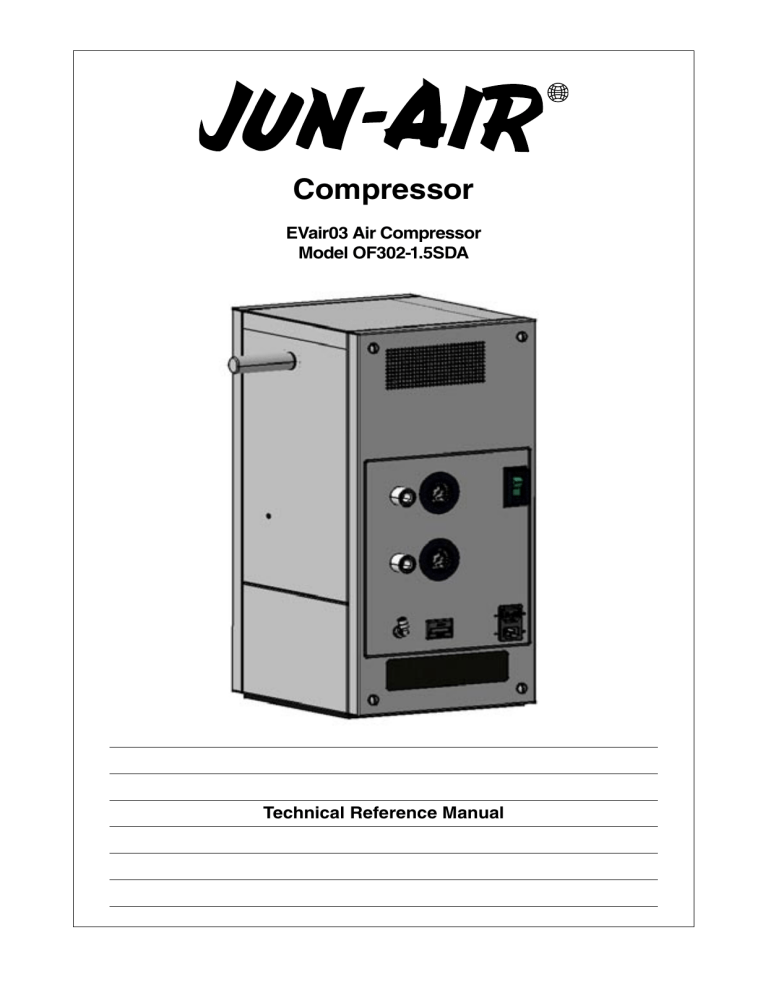
Compressor EVair03 Air Compressor Model OF302-1.5SDA Technical Reference Manual Technical manual IMPORTANT: General directions for use Note • Protect compressor against rain, moisture, frost and dust. • OF302 is constructed and approved for a max. pressure of 8 bar/120 psi. • Do not operate compressor at ambient temperatures exceeding 40°C/104°F or falling below 0°C/32°F. • Technical competence: The procedures described in this Technical Reference Manual should be performed by trained and authorized personnel only. Please note that pictures and figures referred to may be found on page 5-10. Maintenance should only be undertaken by competent individuals who have general knowledge and experience with devices of this nature. IMPORTANT - read this first! No repairs should ever be undertaken or attempted by anyone not having such qualifications. Please read the following information and operating instructions included with this product before use. This information is for your safety and it is important that you follow these instructions. It will also help prevent damage to the product. Failure to operate the unit in accordance with the instructions or using JUN-AIR unauthorized spare parts can cause damage to the unit and could cause serious injury. CAUTION: To reduce risk of electric shock • Only authorized service agents should carry out service. Removing parts or attempting repairs can create an electric shock. Refer all servicing to qualified service agents. • Contact JUN-AIR for a list of approved agents. • Do not use this unit with electrical voltages other than stated on the rating plate. • Always unplug this unit immediately after use. • Store in a dry place. • Do not use this product or install in or near liquid or where it can fall or be pulled into water or other liquids. In which case protection is required. • Do not reach for this product if it has fallen into liquid. Unplug immediately. • This unit is not weatherproof. Never operate outdoors in the rain or in a wet area. • Do not pump any other gases other than atmospheric air. • Do not pump combustible liquids or vapours with this product. • Do not use this unit near naked flames. Min. 0°C/32°F • Max. 40°C/104°F WARNING: To reduce risk of electrocution Warranty Provided that the operational instructions have been carried out, your JUN-AIR compressor is guaranteed against faulty material or workmanship for 2 years. The guarantee does not cover damage caused by violence, misuse, incorrect repairs or use of unoriginal spare parts. Costs of transportation of parts/equipment are not covered by the guarantee. JUN-AIR’s Conditions for Sale and Delivery will generally apply. JUN-AIR International A/S reserves the right to change technical specifications/ constructions. DANGER: To reduce risk of explosion or fire Installation CAUTION: To prevent injury • Compressed air can be dangerous; do not direct airflow at your body. • Always keep the compressor out of reach of children. • Never operate this product if it has a damaged power lead or plug, if it has been dropped or damaged, or if it has fallen into water. Return the product to a service centre for examination and repair. • Keep the electrical cable away from heat. • Never restrict fans. Ensure that all openings are kept free of restriction. • Never insert fingers or any other objects into fans. • This unit is thermally protected and will automatically restart when the overload resets. • Wear safety glasses. • Use only in well-ventilated areas. • Do not use any items not recommended for use with compressed air. • The surface of the compressor can get hot. Do not touch compressor motor during operation. Your JUN-AIR compressor is very easy to operate. Observe the following simple instructions and you will get many years’ service from your compressor. • Visually inspect unit for shipping damage, contact your supplier immediately if you think the unit may have been damaged. • If compressor is to be installed in a ventilator cart, follow manufacturer's installation instructions. Failure to observe the above safety precautions could result in severe bodily injury, including death in extreme cases. 2 Technical Reference Manual 6189655 - v.11 - 01.2004 Electrical supply Weekly WARNING! Incorrect electrical connection may result in electric shock. The electrical connection must be carried out in accordance with local electrical regulations and by qualified electrical engineers. • For electrical connection, refer to page 8. • The EVair03 Air compressor is designed to operate from electrical mains supply. • Verify that your local mains supply voltage matches the rated device voltage on the serial number plate of the compressor. • Connect the power cord to the mains inlet on the rear of the compressor cabinet. • Connect the power cord to the wall outlet. • Switch on the mains switch. Verify that the ON-OFF switch on the front of the compressor unit is lit. • Open drain valve on receiver, if water in receiver, refer to "Fault finding and repair" point 7. Check motor, air tubes, hoses and equipment for leaks. Clean unit or wipe with a soft, damp cloth. If necessary, use paraffin on rag to remove sticky adhesions. Dust and dirt prevent cooling. Replace intake filters (P/N 5412400)1 see fig 5a - c. Check the O-ring in the non-return valve and replace, if necessary. (P/N 6243000,6242500)1 see fig 7. Note! Empty receiver of air before dismounting. Operation • Monthly Annually If the temperature of the compressor is extremely low (for instance after transportation or stocking), allow motor to return to room temperature before switching on the compressor. Do not use motor for compression of liquids and dangerous gasses, such as petrol vapour and solvents. Check filter and replace filter elements for optimum efficiency. (P/N 4071230, 4071240)1 see fig 6a-d. Check air inlet filter mat for cabinet. IMPORTANT! Replace if necessary. (P/N 6985795)1. The compressor pump is only suitable for atmospheric air. 1Included in the annual maintenance kit • Do not remove protection covers during operation as it may cause electric shock or risk of other personel injury. Adjustment of pressure switch (see fig 1a+1b) • Ensure that motor is correct for airflow as required. The pressure switch determines whether the unit runs on primary or reserve supply. The left scale (Cut in) indicates at which pressure the unit switches from reserve to primary supply. WARNING! If maximum pressure is exceeded, reduced lifetime may result. The pressure in the left scale (Cut in) minus the differential pressure (Diff.) in the right scale indicates when the unit will switch from primary to reserve supply. • All compressors may run at 100% continuous operation. To adjust the settings, remove the plastic cover. Use the screws above the scales to adjust the pressure (Cut in)/differential pressure (Diff.). • Do not lubricate the oil-less motor with oil, as this will destroy important components. The values for adjusting the pressure switch are: Cut in: Diff: Preventive maintenance Use the annual maintenance kit to change the parts included in the kit. Change motor after 8-10,000 hours, order the 10,000-hour maintenance kit and change the parts included in the kit. 280 kpa / 40.6 psi 30 kpa / 4.35 psi Cut-in adjustment screw: Turn counterclockwise to increase and clockwise to decrease the cut-in pressure. Above this set point the primary supply will have priority. Diff. adjustment screw: Turn counterclockwise to decrease and clockwise to increase the differential pressure. The cut-in set point minus the differential pressure set point indicates the lower set point. Below the lower set point the reserve supply will have priority. Adjustment of relief valve (see fig 2) The relief valve, see fig. 2, determines the maximum pressure on the reserve supply system. To adjust the pressure, pull out the knob. To increase the pressure, turn clockwise and to decrease the pressure, turn counterclockwise. The non-rising adjusting knob includes a locking feature, push in knob after setting, to lock and prevent adjustment. The value for adjusting the relief valve is 550kpa / 79.8psi. 6189655 - v.11 - 01.2004 Technical Reference Manual 3 Safety valve (see fig 3) The safety valve, see fig. 3, will prevent pressure buildup. If the pressure exceeds 1000 kpa/145 psi the valve will open. Non-return valve (see fig. 4 + 7) The EVair03 Air compressor has two non-return valves, one for the primary system and one for the reserve system. The nonreturn valves are used to separate the two systems. Check the non-return valves annually. Before disassembling the non-return valve, empty the tank, using the drain valve. The pressure gauge will not indicate whether there is pressure in the tank. Replace the O-ring in the non-return valves annually (P/N 6243000). 2. Compressor does not start, makes a buzzing sound followed by a clicking noise (cannot start against high pressure): a) The compressor has not been unloaded and there is back pressure on the piston. Make sure that the compressor is unloaded each time it stops. Check unloader valve and replace, if necessary. See fig. 8. b) Leaky non-return valve. Remove the flexible pressure pipe from motor and check for leaking air from the tank. If so, clean or replace O-ring or non-return valve. 3. Compressor works, but pressure does not increase: a) Intake filter clogged. Replace. b) Leaks in fittings, tubes or pneumatic equipment. Check with soapy water. Drain (see fig. 3) The drain cock will empty the tank for condensate. Normally there will not be any condensate in the tank due to the membrane dryer. Occasionally, if the EVair03 Air compressor has not been used for a long time or if the air from the pipeline inlet to the compressor is not dry, there may be water in the tank. c) Defective valve plate. Replace motor. d) Failure in non-return valve which is creating a flow restriction. Replace non-return valve. e) Check relief valve settings, turn clockwise to increase pressure. f) Intake filter (see fig. 5a + 5b + 5c) The intake filter prevents dust and other large particles from getting into the compressor and also reduces the noise level. Change the filter at least once annually. To loosen the intake filter, turn counterclockwise, using the JUN-AIR intake filter key (P/N 4490501). Unloader valve does not close. Clean or replace unloader valve. g) Higher leakage in dryer than normally. Disconnect the tubes to and from the dryer. Assemble the disconnected tubes and check if the pressure increases. If the pressure increases replace the dryer. 4. Loud noise from compressor: a) Dirt or failure in non-return valve. Clean or replace. 5µm and 0.01µm filters (see fig. 6a + 6b + 6c + 6d) The EVair03 Air compressor has 3 filters. Two 5µ filters and one 0.01µ filter. A 5µ filter with manual drain is used for the primary air supply. A 5µ and 0.01µ filter, both with automatic drain, are used for the reserve supply. For further details, refer to the pneumatic diagram. The filters look the same on the outside, however, when changing the filter elements, it is very important to mount the bowls in the right place. The small number labels on the upper part of the filter and on the filter bowl indicate where the bowls are to be mounted. The numbers of the labels have to match each other. 5. Motor gets very hot: a) Leaks. See point 3b. b) Clogged filter. See point 3a. c) Too high ambient temperature. d) Clogged intake filter mat on cabinet. Replace. 6. Compressor does not switch on when primary pressure is too low or does not switch off when primary pressure is too high (see User Manual): a) Check pressure switch for correct adjustment as described in "Adjustment of pressure switch" on page 3. b) If this does not work, the pressure switch is defective and must be replaced. 7. Water in tank (see drain valve fig. 3): Fault finding and repair IMPORTANT! Switch off and isolate from electrical supply before removing any parts from the pump. Empty air receiver of air before dismantling parts of compressor unit's pressure system. 1. Compressor does not start: a) No power from mains. Check circuit breaker and plug. b) Breakage or loose joints in electrical connections. c) Defective capacitor. d) The thermal protection has switched off the pump due to overheating. When cooled the pump will automatically switch on at a suitable operation temperature. Go through the points in point 5 below. a) Primary air inlet does not provide dry air. Check the 5µm filter on the primary supply pipeline to the tank. Press the manual drain valve at the bottom of the filter bowl. If water comes out of this valve, primary air inlet does not provide dry air. The 5µ filter is mounted behind the 5µ and 0.01µ filters, see fig. 6a. b) The 5µ and 0.01µ filters used for the reserve supply may be clogged or there may be dirt in the bowls. Replace filter elements and clean bowls. c) Press the test button on the automatic drain for the filter bowls to make sure that it is working properly. Clean drain valve and pipes or replace. See fig. 6a + 6b + 6c + 6d. Timer for automatic drain is to be set to 2 minutes. d) Defective dryer. Replace dryer. e) The compressor has seized. Replace motor. 4 Technical Reference Manual 6189655 - v.11 - 01.2004 Pictures/figures Fig. 2 - Relief valve Fig. 1b - Pressure switch Fig. 1a - Pressure switch Fig. 3 - Safety valve and drain Fig. - 5a Intake filter Fig. 4 - Non-return valves Fig. - 5b Intake filter key Fig. - 5c Intake filter Fig. 6a - 5µ and 0.01µ filters for reserve supply. The 5µm filter for primary supply, is mounted behind these filters. 6189655 - v.11 - 01.2004 Pictures/figures 5 Fig. 7 - Non-return valve Fig. 6b - 5µ filter with manual drain for primary supply Fig. 6c - 5µ filter with automatic drain for reserve supply Fig. 6d - 0.01µ filter with automatic drain for reserve supply Fig. 8 - Unloader valve and part of dryer 6 Pictures/figures 6189655 - v.11 - 01.2004 6189655 - v.11 - 01.2004 Pneumatic drawing M Filter drain TEC11 Open 0.3 sec/2min Heat exchanger Intake filter Pump Reserve supply All pipes 6mm Februar 9, 2004 R1.20 EVair03 Air Compressor Continuous operating pump Pneumatic diagram 1l water drain bottle Filter 5µ Pipeline inlet Filter 0.01µ Primary supply Unloader valve Membrane dryer DA Pressure switch See spec. Filter 5µ 1.5 l tank w/manual drain Muffler Relief valve See spec. Non-return valve Non-return valve Safety valve See spec. Pipeline output Pneumatic drawing 7 8 November 13, 2003 R1.18 Electrical drawing AC inlet IEC 320 15A plug Circuit breaker 230V: 5A 120V: 9A Pressure switch EVair03 Air Compressor Continuous operating pump Electrical diagram N L Thermal switch M Compressor Capacitor AWG16 AWG16 Temperature switch for fans Hour meter M Fan Unloader valve AC outlet for auxiliary equipment IEC 320 10A socket M Fan Drain valve TEC11 Electrical drawing 6189655 - v.11 - 01.2004 Drawings 6189655 - v.11 - 01.2004 Drawings 9 10 Drawings 6189655 - v.11 - 01.2004 Spare parts 5471001 Filter kit f/OF302-1.5SDA 2 x 4071230 Spare parts kit f/5um filter regulator 3820-21 4071240 Spare parts kit f/0.01um filter 4141-12 2 x 5412400 Intake filter f/OF301 and OF302 motors 6985795 Filter mat f/air intake f/OF302-1.5SDA 5471002 10,000-hour kit 230V/50Hz 2882110 Motor OF302 230V/50Hz vertical 2 x 5414500 Non return valve 4785600 Solenoid valve f/unloader 230V w/plug 4799500 Auto drain 220-240V TEC11 5471003 10,000-hour kit 120V/60Hz 2882210 Motor OF302 120V/60Hz vertical 2 x 5414500 Non return valve 4785650 Solenoid valve f/unloader 120V w/plug 4799600 Auto drain 120V TEC-11 2882110 Motor OF302 230V/50Hz vertical 2882210 Motor OF302 120V/60Hz vertical 3001500 Receiver 1.5l with inspection plug and internally coated, silver CE 4799500 Auto drain 220-240V TEC11 4799600 Auto drain 120V TEC-11 5095000 Vacuum switch 5150025 Gauge Ø40 built-in 5237007 Capacitor, run complete 20uF/230V AC f/OF300 (40 cm) 5240608 Capacitor, run complete 60uF/120V AC f/OF300 (40 cm) 5370055 Handle f/OF302-1.5SDA complete 5414500 Non return valve 5416555 Relief valve V07-200-NNLG 5425500 Safety valve TÜV 10 bar 5447035 Cooler complete 5450155 Fan 120V 4606Z 5451055 Fan 230V 4656Z 6242500 O-ring Ø16.1x1.6 mm 6243000 O-ring Ø7.3x2.4 mm brown f/non-return valve 6253701 Vibration damper f/OF301/OF302 Ø20x30 6264255 Hose kit f/Datex Ohmeda 6295500 Grommet 170211 6976000 Silencer 1/8" 6984492 Front plate complete f/OF302-1.5SDA 6984508 Cabinet plate f/OF302-1.5SDA 120V complete 4071000 Filter 5um w/manual drain 4071001 Filter 5um (without manual drain) 4071056 Filter 0.01um (without manual drain) 4082300 Membrane dryer (DA) 4141700 Rapid fitting 1/4" external x Ø6 6984511 4141701 Rapid fitting elbow 1/4" external cyl. x Ø6 Cabinet plate f/OF302-1.5SDA 230Vcomplete 6984512 Top f/OF302-1.5SDA complete 4141820 Rapid fitting elbow 1/8"internal x Ø6 6984569 Back f/OF302-1.5SDA 230V complete 4142300 Rapid fitting 1/8"xØ4 6984570 Back f/OF302-1.5SDA 120V complete 4142500 Rapid fitting M5x4mm elbow 6985062 ASL Snap lock (complete set) 4146800 Rapid fitting Ø6mmx1/4" elbow 6985562 Mounting plate f/OF302-1.5SDA 4147555 Rapid fitting T-piece Ø6x1/4" 6985795 Filter mat f/air intake f/OF302-1.5SDA 4147556 Rapid fitting T-piece Ø6x1/4" (1/4" side thread) 7020000 Double nipple 1/8" 7024000 Double nipple 1/4" L= 26 mm 7025000 Double nipple 1/4"x1/8" 7025310 Bushing f/autodrain f/metal cabinet 1/8" 7070000 Connection piece f/non-return valve 7070500 Connection piece f/non-return valve model 12 4383205 Bracket f/membrane dryer Ø18mm 4490501 Tool for intake filter OF300 4752000 Hour meter 230V 4752200 Hour meter 120V 4781555 Plug type 0712 f/cabinet 4783955 Switch 230V (A32-4-F-050-COAZMO3) 7071500 T-piece 1/4" (3 x internal) 4783956 Switch 120V (A34-4-F-090-COAZMO3) 7074500 Coupling 1/4" 7171855 Distance piece f/motor vertical 4785600 Solenoid valve f/unloader 230V w/plug 7181000 Elbow 1/4" ext./ext. 4785650 Solenoid valve f/unloader 120V w/plug 7568055 Bushing f/OF302-1.5SDA 6189655 - v.11 - 01.2004 Spareparts 11 Phone: Telefax: +45 96 32 36 00 +45 96 32 36 01 E-mail: Internet: [email protected] www.jun-air.com Technical modifications reserved 6189655 - v.10 - 01.2004 JUN-AIR International A/S Sundsholmen 3-5 Postboks 109 9400 Nørresundby Denmark


