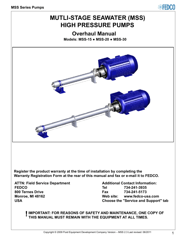
MSS Series Pumps MUTLI-STAGE SEAWATER (MSS) HIGH PRESSURE PUMPS Overhaul Manual Models: MSS-15 ● MSS-20 ● MSS-30 Register the product warranty at the time of installation by completing the Warranty Registration Form at the rear of this manual and fax or e-mail it to FEDCO. ATTN: Field Service Department Additional Contact Information: FEDCO Tel 734-241-3935 800 Ternes Drive Fax 734-241-5173 Monroe, MI 48162 Web site: www.fedco-usa.com USAChoose the "Service and Support" tab FOR REASONS OF SAFETY AND MAINTENANCE, ONE COPY OF ! IMPORTANT: THIS MANUAL MUST REMAIN WITH THE EQUIPMENT AT ALL TIMES. Copyright © 2009 Fluid Equipment Development Company Version – MSS 2.3 Last revised: 06/2011 1 MSS Series Pumps Table of Contents Theory and Operation .............................................................. 3 MSS Pump External Components ........................................ 3 MSS Pump Internal Components ......................................... 4 Overhaul Procedures .............................................................. 5 Warnings and Safety Precautions .................................... .... 5 User Health and Safety .............................................. .......... 6 In The Work Area ...................................................................6 Electrical Connections and Regulations .......................... ..... 6 Lifting and Handling .............................................................. 7 Pump Overhaul ........................................................................ 9 Disassembly ........................................................ ................ 9 Cleaning ............................................................................. 23 Inspection .................................................................. ........ 23 Balance Disc Inspection ................................... ................. 24 Assembly .......................................................... ................. 25 Specifications ......................................................................... 37 Components Exploded Views ............................................ 37 Recommended Spare Parts List ........................................ 39 Service Parts Kits ................................................. ............. 39 Ordering Parts .................................................................... 39 Fastener Specifications ........................................... .......... 40 Concrete Foundation Specifications .................................. 40 Electrical Specifications ..................................................... 40 Pump Alignment Specifications ......................................... 40 Flexible Coupling Specifications ........................................ 40 Balance Disc Specifications .............................................. 40 Lubricants and Compounds ............................................... 40 Maintenance ....................................................................... 41 Service Policy ......................................................................... 42 Storage Requirements ....................................................... 42 Return Authorization Number ............................................. 42 Warranty ........................................................................ .... 43 Warranty Registration Form ............................................... 44 Overhaul Record ................................................................ 45 Start Up Record ...................................................................46 2 Copyright © 2009 Fluid Equipment Development Company Version – MSS 2.3 Last revised: 06/2011 MSS Series Pumps Theory and Operation MSS Pump External Components Multi-stage stainless (MSS) pumps are centrifugal feed pumps specifically designed for brackish and seawater reverse osmosis (SWRO) service. MSS pumps develop pressure by accelerating fluid through a channel. Rotating this fluid through centrifugal force develops a pressure higher than was input. Pressure can be increased by lengthening the channel through the addition of impeller stages or increasing their size. Motors are selected according to equipment operating requirements (Figure 1). A flexible coupling allows the pump shaft to float within the coupling reducing thrust against the motor. The inlet and discharge housings are designed to connect to grooved rigid piping with couplings. The inlet housing itself can be attached to the pump in four different positions 90° apart. A precision leveling foot supports the end shell housing and is fully adjustable to allow accurate pump-to-motor shaft alignment. Typical MSS-15 through MSS-30 Pump External Components 1 11 10 9 8 7 2 6 4 4 3 5 Item Description Item Description 1 Motor 7 Discharge Housing 2 Motor Adapter 8 Cradle 3 Flexible Coupling (inside of Motor Adapter 9 End Shell Housing 4 Support Bracket 10 Series Shell Housing 5 Precision Leveling Foot 11 Inlet Housing 6 Throttle Nipple Figure 1 MSS Pump External Components Copyright © 2009 Fluid Equipment Development Company Version – MSS 2.3 Last revised: 06/2011 3 MSS Series Pumps Theory and Operation (cont.) The balance disc rides in the bearing carrier and serves as a thrust bearing for the pump. This unique design uses patented WATER BEARING™ technology which allows feed water cool and lubricate the disc. Because the balance disc is located at the discharge end of the pump, it keeps the shaft in tension. As the motor rotates the pump, internal pressure causes the impeller stacks to compress and move away from the motor lifting the balance disc off the bearing carrier. Pressure on the front of the balance disc is stabilized by the throttle nipple which allows pressure to travel back through the drain line and into the inlet housing. This thrust and counter thrust allows the disc to "self-balance" based on operating conditions. MSS Pump Internal Components The internal components of an MSS pump can vary depending on pump configuration and number of stages. The basic components contained in a single stage consist of an impeller and a diffuser with a spacers and bushing which prevent friction and wear. Behind the discharge housing at the end of the pump is the cavity cover, balance disc and bearing carrier. (Figure 2). Typical MSS-15 through MSS-30 Pump Internal Components 1 10 8 4 2 5 10 10 12 12 12 6 3 11 11 11 13 13 9 7 Item Description Item Description 1 Pump Shaft 8 End Spacer 2 Cavity Cover 9 Discharge Ring 3 Pump Shaft Nut 10 Impeller 4 Balance Disc 11 Diffuser Bushing (Part of Diffuser Housing) 5 Balance Disc Key 12 Stage Spacer 6 Bearing Carrier 13 Diffuser Housing 7 Water Bearing Components Figure 2 MSS Pump Internal Components 4 13 Copyright © 2009 Fluid Equipment Development Company Version – MSS 2.3 Last revised: 06/2011 MSS Series Pumps Overhaul Procedures Warnings and Safety Precautions Safety practices and precautions for the operation and maintenance of all FEDCO Pump Products MUST BE FOLLOWED. This information supplements oral or written instructions that may be received. Safety MUST be practiced as part of the standard operating procedures for this equipment during any installation and operation. To ensure that safe operating and maintenance procedures are followed, operators should develop and keep up a program of safety checks and current instructions. This manual contains certain operating and maintenance procedures that involve exposure to potentially hazardous situations. The levels of hazardous situations are as follows: DANGER Hazards which are IMMEDIATELY ACCESSIBLE, and capable of causing SEVERE PERSONAL INJURY OR DEATH. WARNING Hazards which are NOT IMMEDIATELY ACCESSIBLE, but are capable of causing SEVERE PERSONAL INJURY OR DEATH. CAUTION Hazards which are NOT IMMEDIATELY ACCESSIBLE, and can cause PERSONAL INJURY. ELECTRICAL HAZARD Hazards which are related to Electrical Components and can RESULT IN ELECTRICAL RISKS, SHOCK, ELECTROCUTION OR DEATH if instructions are not followed properly. PUNCTURE HAZARD Hazards which are NOT IMMEDIATELY ACCESSIBLE and can RESULT IN SEVERE PERSONAL INJURY OR DEATH if instructions are not followed properly. Copyright © 2009 Fluid Equipment Development Company Version – MSS 2.3 Last revised: 06/2011 5 MSS Series Pumps Overhaul Procedures (cont.) WARNING ELECTRICAL HAZARD All pump and safety precautions must be followed to prevent physical injury to the operator. It is illegal to operate the equipment in an EU member state, which requires CE compliance, if the manual is not written in that state’s language. If a translation is needed, please contact a FEDCO representative. Always follow the Lock-out / Tag-out procedure developed by your company before starting any maintenance or repair (Figure 3). CAUTION A pump is a pressure-generating device with rotating parts that can be hazardous. Any device containing generated pressure can rupture, explode or discharge its contents if it is sufficiently over-pressurized and may possibly result in personal injury, property damage, environmental damage and death. All necessary precautions must be exercised to insure over-pressurization does not occur. FEDCO will not accept responsibility for physical injury, damage or delays caused by a failure to observe the instructions in this manual. WARNING Installation, operation or maintenance of the pump unit in any manner which is not covered in this manual could cause damage to the equipment, serious injury or death. This includes any modification to the equipment or the use of parts not provided by FEDCO. If there is a question regarding the intended use of the equipment, please contact a FEDCO representative before proceeding. CAUTION This manual clearly identifies accepted methods for safe disassembly. These methods must be strictly adhered to. WARNING Do not use the pump equipment for a different application than originally specified without the approval of a FEDCO representative. WARNING NEVER operate the pump equipment: ● below the minimum flow rate. ● when dry. ● without priming. ● without proper guards and safety devices installed. ● with the discharge valve closed. ● with the suction valve closed. 6 FRONT BACK Figure 3 Typical Lock-Out Tags User Health and Safety Safety Equipment should be used in accordance with company regulations. The following safety equipment should be used within the work area: • Helmet. • Safety Glasses with shields or goggles. • Safety Shoes. • Protective Gloves. • Hearing Protection is recommended. • Follow safe lifting methods to avoid personal injury. In the Work Area • Always keep the work area clean and dry. • Avoid all electrical dangers. Be aware of risks from electric shock or arc flash hazards. • Utilize adequate lifting equipment and methods. Electrical Connections and Regulations • Refer to the motor nameplate for specific electrical operating information. • Electrical connections must be made by certified electricians in compliance with all international, national, state, and local regulations and codes. • Insure the product is isolated from the power supply and cannot be accidentally energized. • Make sure all thermal contacts are connected to a protection circuit according to product specifications. • All electrical equipment must be properly grounded. • During installation, service and repair, must follow your company’s Lock-out / Tag-out procedure (Figure 3). Copyright © 2009 Fluid Equipment Development Company Version – MSS 2.3 Last revised: 06/2011 MSS Series Pumps Overhaul Procedures (cont.) Lifting and Handling CAUTION Observe all lifting precautions. Failure to follow all lifting and handling precautions may result in serious injury! Unit weight is listed on the unit nameplate. Determine the weight of the unit to select an appropriate lifting method. If the weight of the pump exceeds manual lifting limits, mechanical lifting equipment must be used. MSS pumps can be lifted by the shell using approved lifting straps together with suitable lifting equipment. The straps must be installed around the shell without disturbing the drain line (Figure 5). If straps are placed around the drain line, damage can occur (Figure 4). Pump Assembly Lifting NO Figure 4 Improper Lifting Strap Positioning YES Figure 5 Proper Lifting Strap Positioning Copyright © 2009 Fluid Equipment Development Company Version – MSS 2.3 Last revised: 06/2011 7 MSS Series Pumps Overhaul Procedures (cont.) CAUTION Whenever possible, all components should be lifted and moved separately for safety. Do not lift the pump up by the shaft. If the unit is lifted by the shaft, damage may occur. Lifting and handling of the motor must be performed according manufacturers instructions. Do not lift the pump and motor by the motor eyebolt (Figure 6). The eyebolt is used for lifting the motor only. Motor and Pump Assembly Lifting NO NO Figure 6 Improper Motor and Pump Lifting Points YES Figure 7 Proper Motor and Pump Lifting 8 Copyright © 2009 Fluid Equipment Development Company Version – MSS 2.3 Last revised: 06/2011 MSS Series Pumps Pump Overhaul ELECTRICAL HAZARD Make sure to disconnect the power supply to the motor before carrying out component replacement procedures. Follow all Lock out/Tag out procedures developed by your company before starting any maintenance or repair. Disassembly — All MSS Models 1. Drain piping and pump. 2. Disconnect inlet and outlet piping. 3. Disconnect the thrust bearing drain line from the throttle nipple (Figure 8). Figure 8 Disconnecting Drain Line 4. Remove throttle nipple from discharge housing (Figure 9). Figure 9 Removing Throttle Nipple 5. Remove throttle nipple O-ring from discharge housing (Figure 10). NOTE: Do not discard O-ring. Figure 10 Removing Throttle Nipple O-Ring Copyright © 2009 Fluid Equipment Development Company Version – MSS 2.3 Last revised: 06/2011 9 MSS Series Pumps Pump Overhaul (cont.) 6. Disconnect drain line(s) from inlet housing or high pressure seal carrier (Figure 11). Figure 11 Disconnecting Drain Lines 7. Remove top cradle (Figure 12). Figure 12 Removing Top Cradle 8. Remove anchor bolts and washers from shell support bracket(s) (Figure 13). Figure 13 Removing Shell Support Bracket Bolts 10 Copyright © 2009 Fluid Equipment Development Company Version – MSS 2.3 Last revised: 06/2011 MSS Series Pumps Pump Overhaul (cont.) 9. Remove shell support bracket flange bolts, washers and shell support brackets (Figure 14). Figure 14 Removing Flange Bolts from Support Brackets 10. Remove eight (8) screws and coupling guards (Figure 15). Figure 15 Removing Coupling Guards 11. Support pump assembly using a suitable support jack or crane strap (Figure 16). CRANE STRAP OR SUPPORT JACK Figure 16 Supporting Pump Assembly Copyright © 2009 Fluid Equipment Development Company Version – MSS 2.3 Last revised: 06/2011 11 MSS Series Pumps Pump Overhaul (cont.) 12. Remove motor adapter bolts and washers (Figure 17). Figure 17 Removing Motor Adapter Bolts 13. Install alignment pins to prevent damage to mechanical seal and carefully slide pump from motor (Figure 18). 30.5 cm (12” inches) Figure 18 Separating Pump from Motor 14. Carefully lift and position the pump vertically onto motor adapter (Figure 19). NOTE: Secure pump with fasteners to a stable surface so that it will not tip over during overhaul. STABLE, LEVEL SURFACE Figure 19 Securing Pump for Overhaul 12 Copyright © 2009 Fluid Equipment Development Company Version – MSS 2.3 Last revised: 06/2011 MSS Series Pumps Pump Overhaul (cont.) ADJUSTABLE GUAGE BLOCK 15. Support pump shaft with an adjustable gage block or other suitable fixture (Figure 20). NOTE: The pump must be assembled with the shaft in its correct position. A gage block will ensure assembly in the same position it was disassembled. Figure 20 Supporting Pump Shaft 16. Remove three (3) cap screws, washers and retention clips in discharge housing (Figure 21). Figure 21 Removing Discharge Housing Cap Screws 17. Remove discharge housing retaining ring (Figure 22). Figure 22 Removing Discharge Housing Retaining Ring Copyright © 2009 Fluid Equipment Development Company Version – MSS 2.3 Last revised: 06/2011 13 MSS Series Pumps Pump Overhaul (cont.) 18. Remove discharge housing (Figure 23). Figure 23 Removing Discharge Housing 19. Remove cavity cover (Figure 24). NOTE: Do not discard O-ring. Figure 24 Removing Cavity Cover 20. Use a keyed shaft wrench or other suitable holding device to prevent pump shaft rotation (Figure 25). KEYED SHAFT WRENCH Figure 25 Securing Pump Shaft 14 Copyright © 2009 Fluid Equipment Development Company Version – MSS 2.3 Last revised: 06/2011 MSS Series Pumps Pump Overhaul (cont.) 21. Remove shaft nut, lock washer and washer (Figure 26). Figure 26 Removing Shaft Nut and Washers 22. Remove bearing carrier and balance disc (Figure 27). Figure 27 Removing Bearing Carrier and Balance Disc 23. Remove balance disc key and washer (Figure 28). Figure 28 Removing Balance Disc Washer and Key Copyright © 2009 Fluid Equipment Development Company Version – MSS 2.3 Last revised: 06/2011 15 MSS Series Pumps Pump Overhaul (cont.) 24. Remove balance disc O-ring from shaft (Figure 29). Figure 29 Removing Balance Disc O-Ring 25. if equipped, remove end shell flange bolts and washers (Figure 30). NOTE: Once all flange bolts are removed, the internal stages will decompress causing a slight gap to appear between the shell flanges. This is a normal condition. Figure 30 Removing End Shell Flange Bolts and Washers 26. Carefully lift and remove end shell (Figure 31). Figure 31 Removing End Shell 16 Copyright © 2009 Fluid Equipment Development Company Version – MSS 2.3 Last revised: 06/2011 MSS Series Pumps Pump Overhaul (cont.) 27. Remove discharge ring (Figure 32). Figure 32 Removing Discharge Ring 28. Remove end spacer (Figure 33). NOTE: The end spacer is specially dimensioned for each individual pump. Set this spacer aside for reassembly in its original position. Figure 33 Removing End Spacer 29. Remove impeller (Figure 34). Figure 34 Removing Impeller Copyright © 2009 Fluid Equipment Development Company Version – MSS 2.3 Last revised: 06/2011 17 MSS Series Pumps Pump Overhaul (cont.) 30. Remove diffuser housing (Figure 35). NOTE: Diffuser bushings are integral to the diffuser housings. Figure 35 Removing Diffuser Housing 31. Continue removing A) stage spacer, B) impeller, and C) diffuser housing until all end shell stages are disassembled (Figure 36). C B A Figure 36 Disassembling End Shell Stages 32. Remove end shell O-ring (Figure 37). Figure 37 Removing End Shell O-Ring 18 Copyright © 2009 Fluid Equipment Development Company Version – MSS 2.3 Last revised: 06/2011 MSS Series Pumps Pump Overhaul (cont.) 33. If equipped, remove series shell flange bolts and washers (Figure 38). Figure 38 Removing Series Shell Flange Bolts and Washers 34. If equipped, remove series shell (Figure 39). Figure 39 Removing Series Shell Copyright © 2009 Fluid Equipment Development Company Version – MSS 2.3 Last revised: 06/2011 19 MSS Series Pumps Pump Overhaul (cont.) 35. If equipped, remove series spacer (Figure 40). Figure 40 Removing Series Spacer 36. Continue disassembling each series stage as in Step 31. A) stage spacer, B) impeller, and C) diffuser housing until the first diffuser housing is reached (Figure 41). A B C Figure 41 Disassembling Series Stages 37. Grasp pump shaft and support it by hand and remove first diffuser shell (Figure 42). NOTE: there are no vanes on the rear of the first diffuser housing. Note this for assembly. Figure 42 Removing First Diffuser Shell 20 Copyright © 2009 Fluid Equipment Development Company Version – MSS 2.3 Last revised: 06/2011 MSS Series Pumps Pump Overhaul (cont.) 38. Remove first stage spacer (Figure 43). Figure 43 Removing First Stage Spacer 39. Remove pump shaft (Figure 44). Figure 44 Removing Pump Shaft 40. Remove series shell O-ring (Figure 45). Figure 45 Removing Series Shell O-Ring Copyright © 2009 Fluid Equipment Development Company Version – MSS 2.3 Last revised: 06/2011 21 MSS Series Pumps Pump Overhaul (cont.) 41. Remove inlet ring (Figure 46). Figure 46 Removing Inlet Ring 42. Remove stationary washer and retaining ring (Figure 47). Figure 47 Removing Stationary Washer and Retaining Ring 43. Remove stationary and mechanical seals with washer (Figure 48). NOTE: The shaft retaining ring does not need to be removed unless it is distorted or corroded and needs replacement. Figure 48 Removing Stationary and Mechanical Seals 22 Copyright © 2009 Fluid Equipment Development Company Version – MSS 2.3 Last revised: 06/2011 MSS Series Pumps Pump Overhaul (cont.) Cleaning Inspection WARNING NEVER use petroleum or alcohol based solvents when cleaning pump components. Solvents can degrade or damage vital seals and O-rings over time. Use fresh water with mild soap and rinse all components thoroughly before assembly. Pump Shaft Clean shaft with soap and water. Rinse thoroughly before use. Pay particular attention to shaft ends. Castings Clean all castings with soap and water and rinse thoroughly. Pay particular attention to pipe coupling grooves in inlet and discharge housings. Internal Components Clean all internal castings with soap and water. Rinse thoroughly before use. Internal castings should dried with a with a clean, damp cloth before assembly. Throttle Nipple and Bearing Drain Line Rinse throttle nipple thoroughly using fresh water. Ensure the ports are clear of any debris. Rinse drain line out thoroughly using fresh water and note any debris flushed out. Pump Shaft a) Place the shaft on a flat surface and roll to inspect for any distortion or run-out which may cause vibration. b) Inspect threads - damaged threads can cause the nut to loosen or seize over time and may cause damage. c) Inspect shaft at the coupling end for any signs of excessive wear near the shaft key. Internal Components Inspect all internal components for signs of excessive wear or damage. Pay particular attention to impeller and diffuser fins. Ensure no cracks are present. Replace if necessary. Fasteners Inspect all retaining rings for distortion or corrosion and replace as necessary. Inspect all fastener threads for signs of wear and replace as necessary. O-Rings and Seals Inspect all O-rings for cuts or damage and replace as necessary. Pay particular attention to the mechanical and stationary seals. If either seal shows any signs of excessive wear or leakage, replace both seals. Bushings Inspect all bushings for signs of excessive wear and replace as necessary. Throttle Nipple Pass compressed air through throttle nipple to ensure passages are clear. Replace if necessary. Copyright © 2009 Fluid Equipment Development Company Version – MSS 2.3 Last revised: 06/2011 23 MSS Series Pumps Pump Overhaul (cont.) Balance Disc Inspection FRONT 1. Inspect surfaces of balance disc for unusual wear. Surface may have some wear but should be smooth (Figure 49). REAR SIDE REAR FRONT Figure 49 Inspecting Balance Disc 2. Measure the balance disc outer hub thickness (Figure 50). Refer to the Balance Disc Wear Chart for wear limit specifications. The maximum acceptable balance disc wear is 0.508 mm (0.020”). If the balance disc wear exceeds its wear limit, it must be replaced. Balance Disc Wear Chart Balance Disc Model Original Thickness When New Wear Limit - 0.508 mm (0.020") MSS-15 MSS-20 MSS-30 13.5 mm (0.53") 13.0 mm (0.51”) IF DISC IS WORN MORE THAN 0.0508 cm (0.020”) FROM ORIGINAL THICKNESS, REPLACE BALANCE DISC Figure 50 Measuring Balance Disc 3. Inspect the bearing carrier for unusual wear or scoring and replace if necessary (Figure 51). Figure 51 Inspecting Bearing Carrier 24 Copyright © 2009 Fluid Equipment Development Company Version – MSS 2.3 Last revised: 06/2011 MSS Series Pumps Pump Overhaul (cont.) Assembly 1. Install shaft retaining ring and stationary washer (Figure 52). Figure 52 Installing Stationary Washer and Retaining Ring 2. Install inlet ring (Figure 53). Figure 53 Installing Inlet Ring 3. Install series shell O-ring (Figure 54). Figure 54 Installing Series Shell O-Ring Copyright © 2009 Fluid Equipment Development Company Version – MSS 2.3 Last revised: 06/2011 25 MSS Series Pumps Pump Overhaul (cont.) 4. Install pump shaft and support it by hand until first stabilizing component can be installed (Figure 55). NOTE: Make sure pump shaft is resting on pre-set gauge block. This will ensure pump shaft is installed in the correct position. Figure 55 Installing Pump Shaft 5. Install first stage spacer (Figure 56). Figure 56 Installing First Stage Spacer 6. Install first diffuser shell (Figure 57). NOTE: The first diffuser shell has no vanes on the rear of the shell. Figure 57 Installing First Diffuser Shell 26 Copyright © 2009 Fluid Equipment Development Company Version – MSS 2.3 Last revised: 06/2011 MSS Series Pumps C B A Pump Overhaul (cont.) 7. If equipped, begin installing series stage components in order A) diffuser shell, B) impeller and C) stage spacer. Continue until all series shell stages are installed (Figure 58). Figure 58 Assembling Series Shell Stages 8. If equipped, install series spacer (Figure 59). Figure 59 Installing Series Spacer Copyright © 2009 Fluid Equipment Development Company Version – MSS 2.3 Last revised: 06/2011 27 MSS Series Pumps Pump Overhaul (cont.) 9. If equipped, install series shell (Figure 60). Figure 60 Installing Series Shell 10. Install series shell flange bolts and washers (Figure 61). Tighten to 61 N-m (45 Lb-ft). Figure 61 Installing Series Shell Bolts and Washers 28 Copyright © 2009 Fluid Equipment Development Company Version – MSS 2.3 Last revised: 06/2011 MSS Series Pumps Pump Overhaul (cont.) 11. Install end shell O-ring (Figure 62). Figure 62 Installing End Shell O-Ring C B A 12. Continue installing end stage components in order A) diffuser shell, B) impeller, and C) stage spacer. Continue until all end shell stages are installed (Figure 63). Figure 63 Assembling End Shell Stages 13. Install end spacer (Figure 64). NOTE: The end spacer is specially dimensioned for each individual pump and must be installed in its original position. Figure 64 Installing End Spacer Copyright © 2009 Fluid Equipment Development Company Version – MSS 2.3 Last revised: 06/2011 29 MSS Series Pumps Pump Overhaul (cont.) 14. Install discharge ring (Figure 65). Figure 65 Installing Discharge Ring 15. If equipped, carefully lift and install end shell (Figure 66). Figure 66 Installing End Shell NOTE: A small gap between shell flanges should be noticeable at this time. If no gap is visible, remove the end shell and make sure all stages are accounted for. 16. If equipped, install end shell flange bolts and washers (Figure 67). Tighten to 61 N-m (45 Lb-ft). NOTE: make sure to tighten bolts gradually and evenly to properly compress pump stages. Figure 67 Installing End Shell Bolts and Washers 30 Copyright © 2009 Fluid Equipment Development Company Version – MSS 2.3 Last revised: 06/2011 MSS Series Pumps Pump Overhaul (cont.) 17. Lubricate and install balance disc O-ring (Figure 68). Figure 68 Installing Balance Disc O-Ring 18. Apply system compliant anti-seize compound on balance disc key and install balance disc key and washer (Figure 69). APPLY SYSTEM COMPLIANT ANTI-SEIZE COMPOUND NOTE: Make sure the rounded end of the key is facing outward. Use caution not to drop key during installation. If key is dropped into pump, the pump must be disassembled to retrieve the key. Figure 69 Installing Balance Disc Key and Washer 19. Install bearing carrier into end shell (Figure 70). NOTE: Make sure the discharge housing alignment pin is on top. Figure 70 Installing Bearing Carrier Copyright © 2009 Fluid Equipment Development Company Version – MSS 2.3 Last revised: 06/2011 31 MSS Series Pumps Pump Overhaul (cont.) 20. Install balance disc (Figure 71). NOTE: Make sure balance disc is firmly seated in bearing carrier. Figure 71 Installing Balance Disc 21. Use a keyed shaft wrench or other suitable holding device to prevent pump shaft rotation during shaft nut installation (Figure 72). KEYED SHAFT WRENCH Figure 72 Securing Pump Shaft 22. Apply system compliant anti-seize compound to shaft threads and install washer, lock washer and shaft nut (Figure 73). Tighten to 68 N-m (50 Lb-ft). APPLY SYSTEM COMPLIANT ANTI-SEIZE COMPOUND Figure 73 Installing Shaft Washers and Nut 32 Copyright © 2009 Fluid Equipment Development Company Version – MSS 2.3 Last revised: 06/2011 MSS Series Pumps Pump Overhaul (cont.) 23. Lubricate cavity cover O-ring and install cavity cover (Figure 74). NOTE: Make sure to align the throttle nipple opening to face downward. Figure 74 Installing Cavity Cover 24. Locate the discharge housing alignment pin in the bearing carrier and note the discharge housing alignment cavity (Figure 75). Figure 75 Aligning Discharge Housing 25. Lubricate discharge housing O-ring and install discharge housing (Figure 76). NOTE: Make sure to align throttle nipple opening with throttle nipple opening in cavity cover. Figure 76 Installing Discharge Housing Copyright © 2009 Fluid Equipment Development Company Version – MSS 2.3 Last revised: 06/2011 33 MSS Series Pumps Pump Overhaul (cont.) 26. Temporarily install throttle nipple to ensure cavity cover and discharge housing are properly aligned (Figure 77). 27. Remove throttle nipple. Figure 77 Test Fitting Throttle Nipple 28. Install the discharge housing retaining ring (Figure 78). NOTE: If the retaining ring groove is not visible, pull end shell forward and push discharge housing inward until the retaining ring groove is visible. Figure 78 Installing Discharge Housing Retaining Ring 29. Install retention clips with washers and secure with cap screws (Figure 79). Tighten to 4 N-m (35 Lb-in). Figure 79 Installing Retention Clips and Cap Screws 34 Copyright © 2009 Fluid Equipment Development Company Version – MSS 2.3 Last revised: 06/2011 MSS Series Pumps Pump Overhaul (cont.) 30. Install new throttle nipple O-ring into the discharge housing (Figure 80). Figure 80 Installing Throttle Nipple O-Ring LUBRICATE 31. Apply thread sealing tape to throttle nipple threads and lubricate non-threaded portion of throttle nipple (Figure 81). THREAD SEALING TAPE Figure 81 Taping Throttle Nipple Threads 32. Thread throttle nipple through the discharge housing O-ring and cavity cover (Figure 82). Tighten sufficiently to prevent any leaks. NOTE: Make sure to thread the throttle nipple through the O-ring to prevent dislodging it. Figure 82 Installing Throttle Nipple Copyright © 2009 Fluid Equipment Development Company Version – MSS 2.3 Last revised: 06/2011 35 MSS Series Pumps Pump Overhaul (cont.) 33. Apply thread sealing tape to drain line elbow and reconnect bearing drain line to the throttle nipple (Figure 83). Figure 83 Connecting Drain Line 34. Install stationary and mechanical seals onto pump shaft (Figure 84). Refer to the service manual for seal installation procedures. NOTE: Once assembly is complete, refer to the service manual for installation and alignment procedures. Figure 84 Installing Mechanical and Stationary Seals 36 Copyright © 2009 Fluid Equipment Development Company Version – MSS 2.3 Last revised: 06/2011 MSS Series Pumps Specifications (cont.) Components Exploded Views External Components 6 5 4 8 7 1 2 3 11 10 9 12 13 18 14 15 16 19 17 Figure 85 Pump Assembly External Components Item Description Item Description 1 Throttle nipple O-ring 11 Shaft bushing 2 Throttle nipple 12 Support bracket 3 Drain line 13 Precision leveling foot 4 Inlet ring 14 End shell 5 Inlet housing 15 End shell O-ring 6 Inlet housing bolts 16 Shell flange bolts 7 Coupling guards 17 Series shell 8 Coupling guard bolts 18 Series shell O-ring 9 Motor adapter 19 Flexible coupling assembly 10 Motor adapter bolts Copyright © 2009 Fluid Equipment Development Company Version – MSS 2.3 Last revised: 06/2011 37 MSS Series Pumps Specifications (cont.) Components Exploded Views Internal Components 12 11 9 1 2 3 5 4 6 8 13 24 10 23 7 14 15 16 17 22 21 20 19 29 18 Figure 86 Pump Assembly Internal Components Item Description Item Description 1 Cap screws (3 Req'd) 16 Stage spacer 2 Retaining clips (3 Req'd) 17 Diffuser housing 3 Discharge housing retaining ring 18 Balance disc O-ring 4 Discharge housing 19 Balance disc washer 5 Discharge housing O-ring 20 Balance disc key 6 Cavity cover 21 Series spacer 7 Cavity cover O-ring 22 Shaft collar assembly 8 Pump shaft nut 23 Shaft retaining ring 9 Lock washer 24 Shaft washer 10 Washer 25 Mechanical seal assembly 11 Balance disc 26 Stationary seal 12 Bearing carrier 27 Inlet washer 13 Discharge ring 28 Inlet retaining ring 14 Impeller 29 Pump shaft 15 Diffuser bushing 38 Copyright © 2009 Fluid Equipment Development Company Version – MSS 2.3 Last revised: 06/2011 26 25 28 27 MSS Series Pumps Specifications (cont.) Recommended Spare Parts List 1-3 years of service A maintenance kit (P/N 8-M0015-MTK) and a retaining ring kit (P/N 8-M0015-RTK) should be kept on hand. The maintenance kit consists of a balance disk, mechanical seal and O-rings. The retaining ring kit consists of all retaining rings in the assembly. 4-5 years of service A complete disassembly, cleaning and inspection of all pump components is recommended. An overhaul kit and stage kit should be made available before beginning this procedure. Refer to the "Service Parts Kits" chart below for specific pump models. Service Parts Kits Part Number Description 8-M0015-ORK O-Ring kit 8-M0015-BDK Balance disc kit 8-M0015-MSK Mechanical seal kit 8-M0015-TNK Throttle nipple kit 8-M0015-RTK Retaining ring kit 8-M0015-ALK Alignment kit 8-M0015-MTK Maintenance kit 8-M0015-STK Stage kit (Model MSS-15) 8-M0020-STK Stage kit (Model MSS-20) 8-M0030-STK Stage kit (Model MSS-30) 8-M0015-OHK Overhaul kit (Model MSS-15) 8-M0020-OHK Overhaul kit (Model MSS-20) 8-M0030-OHK Overhaul kit (Model MSS-30) Ordering Parts ATTN: Field Service Department Additional Contact Information: FEDCO Tel 734-241-3935 800 Ternes Drive Fax 734-241-5173 Monroe, MI 48162 Web site: www.fedco-usa.com USAChoose the "Service and Support" tab Copyright © 2009 Fluid Equipment Development Company Version – MSS 2.3 Last revised: 06/2011 39 MSS Series Pumps Specifications (cont.) Fastener Torque Specifications Item Precision leveling foot top cradle nuts Motor adapter bolts - 3/8" Motor adapter bolts - 1/2" Support bracket adjustment bolts Inlet housing bolts Inlet housing bolts (high pressure seal carrier) End shell flange bolts MSS-15 through MSS-30 Series shell flange bolts MSS-15 through MSS-30 Pump shaft nut MSS-15 through MSS-30 Discharge housing retaining clip cap screws Metric 149 N-m 28 N-m 61 N-m 61 N-m 28 N-m 28 N-m 61 N-m 61 N-m 68 N-m 4 N-m Standard 110 Lb-ft 21 Lb-ft 45 Lb-ft 45 Lb-ft 21 Lb-ft 21 Lb-ft 45 Lb-ft 45 Lb-ft 50 Lb-ft 35 Lb-in Concrete Foundation Specifications Foundation Mass Total equipment weight + 50% No less than 15 cm of space on all sides of pump and motor Foundation Size No less than 5.9"on all sides of space on all sides of pump and motor Electrical Specifications All electrical connections shall be completed in conformance will all local electrical codes and regulations. All European Union countries must follow EN 60204-1. It is recommended that all units using variable frequency drives use shielded cable between the VFD and motor. Shielding on all cables must be connected on both ends. Pump Alignment Specifications Flange Gap Tolerances for non-uniform gaps Good 0.53 mm 0.021" Acceptable 0.81 mm 0.032" Flexible coupling Gap between flexible coupling disc pack and end of motor shaft 3.2- 6.4 mm Balance Disc Specifications Pump Model MSS-15 through MSS-30 Original Thickness When New 13.5 mm (0.53") Wear Limit 0.508 mm (0.020") 13.0 mm (0.51") Lubricants and Compounds Lubricants Anti-seize compound 40 Standard Glycerine lubricant or soap and fresh water Must be system compliant Copyright © 2009 Fluid Equipment Development Company Version – MSS 2.3 Last revised: 06/2011 0.13"- 0.25" MSS Series Pumps Specifications (cont.) Maintenance By following the schedule of preventive maintenance presented below, the MSS pump will deliver years of trouble-free performance. One (1) day after commissioning 1. Recheck pump alignment (refer to Final Pump Alignment). 2. Visually inspect coupling and tighten the coupling bolts to the specified torque as necessary. 3. Fill out and submit all warranty documentation to FEDCO. Six (6) months after commissioning 1. Inspect pump alignment (refer to Final Pump Alignment). 2. Inspect flexible coupling: check for wear, irregularities, torsional backlash, running behavior and tightening torque (refer to Flexible Coupling Check). 3. Inspect for leaks, damaged gaskets and condition of all roll grooved couplings. 4. Wipe pump, motor and baseplate with a clean, damp cloth. Twelve (12) months after commissioning 1. Inspect pump alignment (refer to Final Pump Alignment). 2. Inspect flexible coupling: check for wear, irregularities, torsional backlash, running behavior and tightening torque (refer to Flexible Coupling Check). 3. Inspect mechanical seal for early signs of leakage or failure. 4. Inspect balance disc (refer to Balance Disc). 4a. Note: If balance disc requires replacement, mechanical seal should also be replaced. 5. Inspect for leaks, damaged gaskets and condition of all roll grooved couplings. 6. Wipe pump, motor and baseplate with a clean, damp cloth. Annually 1. Inspect pump alignment (refer to Final Pump Alignment). 2. Inspect flexible coupling: check for wear, irregularities, torsional backlash, running behavior and tightening torque (refer to Flexible Coupling Check). 3. Inspect for leaks, damaged gaskets and condition of all roll grooved couplings. 4. Inspect balance disc (refer to Balance Disc). 4a. Note: If balance disc requires replacement, mechanical seal should also be replaced. 5. Inspect for leaks, damaged gaskets and condition of all roll grooved couplings. 6. Wipe pump, motor and baseplate with a clean, damp rag. Five (5) Years 1. Annual maintenance per above. 2. Disassemble fluid end for detailed inspection (refer to Overhaul). Note: Follow manufacturer's recommendations for motor and VFD maintenance. Copyright © 2009 Fluid Equipment Development Company Version – MSS 2.3 Last revised: 06/2011 41 MSS Series Pumps Service Policy Storage Requirements The MSS pump must be protected from moisture, sand, grit, and other foreign matter. Do not remove the protective covers from the pipe connections until ready to install. For long-term storage, keep pump and all other components in its original crate away from moisture, sand or dust. Return Authorization Number (RAN) Please contact a FEDCO before returning any equipment. You must have a Return Authorization Number (RAN) issued by FEDCO before we can accept any parts. All returned parts must be shipped prepaid to FEDCO with the RAN clearly marked on the package. We need this number to ensure proper handling of the returned parts and supply of new parts, if needed. Repair by FEDCO on equipment that is out-of-warranty will be warranted for three (3) months. Ask FEDCO for details of the repair warranty. Parts will be replaced in accordance with the FEDCO warranty. Use the following address to return parts: ATTN: Field Service Department Additional Contact Information: FEDCO Tel 734-241-3935 800 Ternes Drive Fax 734-241-5173 Monroe, MI 48162 Web site: www.fedco-usa.com USAChoose the "Service and Support" tab Procedure How to Return Parts to FEDCO 1. Provide FEDCO with the following information: • Serial number of unit. • Description of why parts are being returned. 2. FEDCO will provide a Return Authorization Number. 3. Pack the unit in the original shipping crate or other suitable crate and clearly mark the Return Authorization Number on the outside of the crate. 4. Send unit, freight prepaid, to FEDCO at the above address. 42 Copyright © 2009 Fluid Equipment Development Company Version – MSS 2.3 Last revised: 06/2011 MSS Series Pumps Service Policy (cont.) Warranty Fluid Equipment Development Company, LLC, (FEDCO), warrants its MSS feed pump to be free from defects in design, materials or workmanship for a period of 18 months from shipment or 12 months from the date of installation of the product, whichever occurs first, when said product is operated in accordance with written instructions and is installed properly. If the MSS pump is altered or repaired without prior approval of FEDCO, all warranties are void. All equipment provided by FEDCO, including pump motors, must be installed on a rigid, steel support structure and base capable of handling full loads during operation. Failure to do so will void warranty. All equipment must be installed such that there are no pipe stresses on FEDCO equipment. Failure to do so will void warranty. If the MSS pump is not installed and aligned as per FEDCO Installation and Operation Manual, any subsequent damage to the pump and/or motor will be excluded from the warranty. If any defects or poor performance occur during the warranty period, FEDCO's sole obligation shall be limited to alteration, repair or replacement at FEDCO's expense, F.O.B. factory, of any parts or equipment, which upon return to FEDCO and upon FEDCO's examination prove to be defective. All parts returned for warranty service must be shipped prepaid and include FEDCO's return authorization number. Equipment and accessories not manufactured by FEDCO are warranted only to the extent of and by the original manufacturer's warranty. FEDCO shall not be liable for damage or wear to equipment caused by abnormal conditions, excessive temperatures, and vibration or caused by corrosives, abrasives or foreign objects. The foregoing warranty is exclusive and in lieu of all other warranties, whether expressed or implied, including any warranty of merchantability or fitness for any particular purpose. In no event shall FEDCO be liable for liable for consequential or incidental damages. Declaration of Conformity This product fulfills the obligations of the applicable EU directives. The declaration of conformity is a standalone document and can be requested, if required, from FEDCO or any FEDCO representative. Register the product warranty at the time of installation by completing the Warranty Registration Form on the following page and sending it to FEDCO. Copyright © 2009 Fluid Equipment Development Company Version – MSS 2.3 Last revised: 06/2011 43 MSS Series Pumps Service Policy (cont.) Warranty Registration Form THIS FORM MUST BE COMPLETED AND RETURNED TO FEDCO TO ACTIVATE YOUR WARRANTY COVERAGE. FEDCO will send confirmation of start of warranty coverage Please FAX this page to FEDCO to register your warranty. Retain the original for your future information. FAX to: +734.241-5173 (USA) or E-MAIL: www.fedco-usa.com and choose the "Service and Support" tab. Initial Installation Model #: ________________________________ Serial #: _______________________________ Installation Date: _________________________ Startup Date:____________________________ VFD frequency (Hz) if used _________________ Voltage and Hz of power supply_____________ Feed Flow: ______________________________ Suction Pressure to Pump: _________________ Discharge Pressure: ______________________ Drain flow rate (high inlet pressure option only): _________________________ Comments: _______________________________________________________________________________ _______________________________________________________________________________ _______________________________________________________________________________ _______________________________________________________________________________ _______________________________________________________________________________ Installed by: __________________________ Telephone: __________________________ Fax: ________________________________ E-mail:______________________________ 44 Copyright © 2009 Fluid Equipment Development Company Version – MSS 2.3 Last revised: 04/2011 MSS Series Pumps Service Policy (cont.) Overhaul Record Overhaul Date: _____________________________ Operating Hours: ___________________________ Reason for Overhaul: ______________________________________________________________ _______________________________________________________________________________ _______________________________________________________________________________ Operating Data Prior to Overhaul: Feed Flow: _____________________________ Suction Pressure to Pump: ___________________ Discharge Pressure: _____________________ Operating Data After Overhaul: Feed Flow: _____________________________ Suction Pressure to Pump: ___________________ Discharge Pressure: _________________________ GENERAL NOTES: _______________________________________________________________________________ _______________________________________________________________________________ _______________________________________________________________________________ _______________________________________________________________________________ _______________________________________________________________________________ _______________________________________________________________________________ _______________________________________________________________________________ Overhauled by: __________________________ Telephone: _____________________________ Fax: ________________________________ E-mail: ________________________________ Copyright © 2009 Fluid Equipment Development Company Version – MSS 2.3 Last revised: 06/2011 45 MSS Series Pumps Service Policy (cont.) Start Up Record Start Up Check List 1. Flexible coupling set screws tightened. 2. Motor adapter guards installed. 3. All anchor bolts tightened to specifications. 4. All pipe couplings tightened to specifications. 5. Motor rotational direction correct. 6. Motor lubricated to manufacturers specifications. 7. Final Pump Alignment performed. 8. Inlet pressure indicator installed. 9. Inlet pressure switch (if applicable) installed. 10. Outlet pressure indicator installed. 11. System pipes are clean and upstream filtration in place. 12. System leak checked and all air vented from system. 13. ALL safety devices in place. Installation and Start-up Information Start-up Date: _________________________ Model #: _________________________________ Serial #: ______________________________ Installation Date:___________________________ Installed By: ___________________________ Operating Conditions Feed Flow: ____________________________ Suction Pressure to Pump:___________________ Discharge Pressure: _____________________ Drain flow rate (high inlet pressure option only): _________________________ VFD frequency (Hz) if used ________________ Voltage and Hz of power supply_______________ VFD Amps: ____________VFD Amps (after 48 hours of running time): ______________________ GENERAL NOTES: _______________________________________________________________________________ _______________________________________________________________________________ _______________________________________________________________________________ _______________________________________________________________________________ _______________________________________________________________________________ _______________________________________________________________________________ This report has been filled out by: __________________________________Date: _____________ Copyright © 2009 Fluid Equipment Development Company Version – MSS 2.3 Last revised: 06/2011 46
