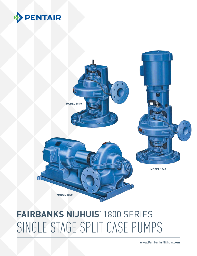
Model 1810 Model 1840 Model 1820 FAIRBANKS NIJHUIS 1800 Series ™ SINGLE STAGE SPLIT CASE PUMPS www.FairbanksNijhuis.com SINGLE STAGE SPLIT CASE PUMPS FAIRBANKS NIJHUIS 1800 Series ™ Single Stage Split Case Pumps Capacities to 15000 GPM (3407 m3/hr) Heads to 663 Ft. (202 m) Temperatures to 275˚F (135˚C) Introduction The horizontal split case pump has long and properly been used for the handling of liquids where the utmost in reliability and accessibility are paramount. Billions of gallons of liquid have been pumped by split case double suction pumps and billions more will be pumped considering the rapid industrial, agricultural and commercial expansion. The Fairbanks Nijhuis 1800 Series pumps make a significant contribution to the customer requirements for pumps on this type of service. The 1800 Series is a modern design based on Fairbanks Nijhuis’s over 130 years of experience with the design, sales and manufacturing of split case pumps. Look through this bulletin and see what real accomplishments can be made when an imaginative approach is taken to the customer’s problem of moving liquids within a piping system. Models 1820 are horizontally baseplate mounted with a driver flexibly coupled to the pump. This design is recommended where floor space is readily available and where flooding of the installation is not possible. Model 1810 Model 1840 Model 1820 VERTICAL MODEL 1840 OPTIONAL RIGHT-HAND ROTATION VERTICAL MODEL 1810 OPTIONAL LEFT-HAND ROTATION Models 1810 are vertically mounted and utilize flexible shafting between the driver and the pump. This model is frequently used on difficult applications where flooding of the installation is a possibility. Models 1840 are vertically mounted with an elevated driver coupled directly to the pump thru a flexible coupling. Model 1840 is very popular for installations where available floor space is limited and where possible flooding is marginal. 2 HORIZONTAL MODEL 1840 SPACE SAVING VERTICAL SPLIT CASE PUMPS – PUT THE MOTOR ABOVE FLOOD CONDITIONS SINGLE STAGE SPLIT CASE PUMPS Pump Features DISCHARGE Standard Features • Bronze fitted pump construction • Internal bypass between casing and stuffing box • Bronze shaft sleeves • 125# ASA flanges • Dynamically balanced impellers • 250 psi case working pressure • Bronze case wearing rings • Twin volute on 10" and larger pumps • Stainless steel impeller key • Carbon steel shaft SUCTION • Stuffing box bushings STANDARD RIGHT-HAND ROTATION • Lifting lugs • Regreaseable ball bearings • Hydrostatic test • Single row ball bearing (inboard) • Double row ball bearing (outboard) • Mechanical seals...single unbalanced (Model 1810 and 1840) • Graphite and TFE lubricated acrylic packing • Cast integral bearing arms DISCHARGE • Water slingers and grease seals • Coupling guard (Model 1820) • All iron, all bronze or special alloy pump construction SUCTION SUCTION STANDARD OPTIONAL DUAL DRIVE RIGHT-HAND ROTATION • External bypass between casing and ROTATION RIGHT-HAND stuffing box (Model 1820) • Hardened 440C stainless steel shaft • Steel drip rim, formed steel or sleeves (packing only) fabricated steel bases DISCHARGE DISCHARGE • 316 stainless steel shaft sleeves (mechanical seal) DISCHARGE • Right- or left-hand rotation • Certified performance test • Oil lubricated ball bearings (Model 1820 horizontal pump) • Packing with lantern ring (Model 1820) • Mechanical seals – single unbalanced (Model 1820) – single balanced (all models) SUCTION • 250# ASA suction and discharge flanges • Bottom suction or chairmounted pumps • Water cooled cartridge caps SUCTION STANDARD RIGHT-HAND ROTATION www.FairbanksNijhuis.com LEF • Double extended shaft (Model 1820) • Impeller wearing rings • Stainless steel or Monel shaft DISCHARGE • External bypass between casing and stuffing box (Model 1810 and 1840) Optional Features ® OPTIO RIGHT OPTIONAL DUAL DRIVE RIGHT-HAND ROTATION SUCTION OPTIONAL LEFT-HAND ROTATION 3 SINGLE STAGE SPLIT CASE PUMPS Horizontal Pump Features A B E D C G I F H A. B. C. D. 4 Split Case Design simplifies disassembly. The suction and discharge piping and alignment is not disturbed. Simply remove the upper casing for service or inspection. Cast lifting lugs are provided. Computer-machined major components with 360 degree registered fits assure concentricity of all parts. Twin volute design balances out radial hydraulic thrust loads on larger split case pumps (see Range Charts). E. F. Dynamically Balanced Impeller is keyed to the shaft and secured by adjustable shaft sleeves. Double suction design balances out hydraulic thrust loads. Vacuum cast process and proven design provides high efficiency and performance. Bronze Shaft Sleeve prevents shaft wear, is slip fit over the shaft, keylocked, and extends the entire length of each stuffing box. Shaft sleeves and impeller are O-ring sealed to eliminate corrosion of the shaft by the pumped liquid. This eliminates the need for high cost, special stainless steel or Monel® shafts. G. H. Interchangeable Stuffing Box for mechanical seals or packing. Packing is standard on horizontal pumps. Optional lantern rings have internal water seal passages between the casing and stuffing box and cannot be damaged. Mechanical seals have carbon against Ceramic face. Long life is assured with 303 stainless steel metal parts and Buna-N elastomers. Several optional mechanical seals are available. I. Grease Lubrication purges old grease from bearing. Oil lubrication is optional on horizontal pumps. Lube fittings are conveniently located for quick access and provide positive bearing lubrication. Oil seals and non-sparking neoprene rotating slingers protect both bearings during pump operation and washdowns. Bearings selected for 50,000 hour minimum life at maximum load. Average bearing life 5 x minimum. Double row thrust ball bearing is standard on all models. Short bearing span holds shaft deflection to .002" at face of stuffing box at maximum load. Integral bearing arms eliminate bearing misalignment and simplify service. Left-Hand Rotation can be readily provided with standard parts. Tandem drive pumps require only a different shaft. Certified Performance with positive suction pressure or with a suction lift is available on each pump for customer approval. Pumps are all hydrostatically tested. Case Wearing Rings and throttle bushings prevent wear on the pump casing and are easily and inexpensively replaced. SINGLE STAGE SPLIT CASE PUMPS Vertical Pump Features A Key Features A. B B. D Mechanical Seals Standard construction includes carbon against Ceramic face for optimum hot water performance. Long life is also assured with 303 stainless steel metal parts and Buna-N elastomers. C. Bearing Protection D. Cast Iron Drip Rim Base Model 1840 C Coupling Alignment with true alignment is vital to long life and proper performance. To maintain proper coupling alignment, the mounting bracket is rabbet fitted to the motor. Grease seals and water slingers are provided to protect the bearings from contamination. This important feature is also standard on horizontal pumps. Accurate positioning of the pump is assured by the mounting base. A drip rim is incorporated in the base design to control condensation and leakage. Benefits Go vertical and put two pumps where only one horizontal would fit. Fairbanks Nijhuis’s™ space saving vertical split case pumps have long been recognized for their reliability. This reputation in the field of vertical installations has been re-emphasized since the introduction of the Model 1840 as pumps of unmatched quality. Vertical pumps provide distinct advantages over horizontal pump construction. EXTERNAL UPPER SEAL FLUSH • Less floor space required. • Inline piping arrangement allows piping in any direction. • Elevated motor protects against potential flooding if the pump station is in a low area. Additional features described for the horizontal pumps are also found in the vertical pumps. There are several features unique only to Model 1840. www.FairbanksNijhuis.com 5 SINGLE STAGE SPLIT CASE PUMPS Range Charts Single Volute 3500 RPM 900 800 Individual performance curves should be checked for final selection. For selections not shown on this chart, please refer to the factory. 700 6" 1 600 823H 822C 3B H 182 H 22 /2" 823 823C 4" 1 823D 3" 1 824C 3" 1 824B 18 2-1 2" 1 300 Power Frame No. 1 Power Frame No. 2 Power Frame No. 3 5" 1 4" 1 400 6" Power Frame No. 4 Power Frame No. 4A Power Frame No. 5A 2" 1 824 200 4" 182 2B TOTAL DYNAMIC HEAD – FEET 500 H 100 90 80 70 60 50 30 40 60 90100 200 300 400 600 800 1000 2000 3000 5000 9000 CAPACITY – GALLONS PER MINUTE 50 2 3 45 4 5 6 7 40 1000 RPM 6" 1822 6" 1823 8" 1823A 8" 1822A 6" 1824C 10" 1823C 8" 1825A 1 Individual performance curves should be checked for final selection. For selections not shown on this chart, please refer to the factory. 10" 1824 D 7 Power Frame No. 1 Power Frame No. 2 Power Frame No. 3 Power Frame No. 4 8" 1825 35 6" 18 825 6" B 24 A 82 4A 4 82 "1 "1 10 4 10 10 B "1 12" 1823 3B 82 "1 2B 82 1 8" 1 4 1B A 10 3 182 1 18 22 18 A 23 18 4" D 23 5" 4" 5 8" 4 3B 2 182 6 182 /2" 8" 2-1 182 B 23 2" 1 825 10 0 824 24 18 15 4" 1 824 5" 825 18 3" 1 8" 1 5" 20 14 12" B 24 18 25 5 18 6" HEAD (m) 25 4" 1 30 Power Frame No. 5 Power Frame No. 6B Power Frame No. 7 Power Frame No. 7A 822 100 1000 10000 FLOW (m3/hr) .5 6 3 IN 444A142 MAX. SPHERES IM P. PAT T. N O . 50 160 40% 18.25" 50% 60% 65% 71% 140 17" 40 71% 120 70% HEAD (FEET) (METERS) 15.5" 30 65% 100 60% 4 NPSH 5 NPSH 80 15 HP 6 NPSH 20 7 NPSH 60 30 HP 8 NPSH 25 HP 10 NPSH 40 10 20 HP 20 6 U.S. GPM US M3/HR 100 200 10 300 400 20 40 500 30 80 600 700 40 120 800 900 50 160 1000 60 200 2PC-117376 Performance Curves The individual curve for the size pump selected is found in catalog section 1800. These performance curves give complete operating characteristics, efficiency, horsepower, and N.P.S.H. required. Horsepower lines on these curves are based on specific gravity of 1.0. To obtain the horsepower for a liquid of a different specific gravity, multiply the horsepower obtained from the curves by the specific gravity of that liquid. The performance curve illustrated to the left is typical of the individual curves readily available for each pump size. C A S E PAT T. N O . 1 8 0 A 2 1 5 U P P E R (A L L ) 1 8 0 A 2 1 6 L O W E R (1820) 1 8 0 A 2 5 9 L O W E R (1810 & 1840) MIN. IMP. DIA. 1 5 .5 IN 240 SINGLE STAGE SPLIT CASE PUMPS Range Charts 1 400 2 3 4 5 300 6 1150 RPM 6" 1824A 6" 1824C 6" 1825 8" 1823A 8" 1825A 10" 1823B Individual performance curves should be checked for final selection. For selections not shown on this chart, please refer to the factory. Power Frame No. 1 Power Frame No. 2 Power Frame No. 3 Power Frame No. 4 8" 18 25 3 4" 1 6" 1 825B 823 50 824 823A 40 821 B "1 82 4A 14 "1 82 4 6" 18 22 30 6 4 8" 1 4 2B A 22 18 4" 1 82 Power Frame No. 5 Power Frame No. 6B Power Frame No. 7 Power Frame No. 7A 12" 1823 B 10" 1824 D 5" 1 2" 1 12 "1 82 "1 823C 10 10" 1 A 822 8" 1 2-1/ 825 10 B 23 18 8" 2" 1 824 824 825 2 B 24 18 8" 4" 1 3" 1 5 1 823 6" 1 100 90 80 70 60 824B 5" 1 5" TOTAL DYNAMIC HEAD – FEET 200 8" 18 22 20 20 30 40 50 60 80 100 200 300 400 500 600 800 1000 2000 3000 4000 5000 7000 10000 20000 CAPACITY – GALLONS PER MINUTE 900 800 700 600 500 1 2 3 4 5 6 7 400 3" 4" 6" 6" 6" 6" 6" 1824C 1823C 1823 1824B 1824A 1824C 1825 8 9 10 1750 RPM 8" 1824B 8" 1825A 10" 1823B 7 4" Power Frame No. 5 Power Frame No. 6B Power Frame No. 7 Power Frame No. 7A 23B B 1B C 22B 822 8" 1 824B 30 5" 1822 3B 3" 1 Power Frame No. 1 Power Frame No. 2 Power Frame No. 3 Power Frame No. 4 12" 18 A 4" 18 " 182 40 2 D 24 8" 182 1 18 6" 1822 2" 23 823 3 10 823 5" 1 82 A 2 18 2" 1 2A 4" 1 4" 80 70 60 50 182 8 12" 182 4A "1 82 4 10 D 100 824 4 6 4 5 10" 1824 2" 1 5" 182 2 3C 82 82 "1 10 "1 10 2A B 182 23 8" 18 8" 3A 182 2-1/ 5" 8" 825 5B 824 825 2" 1 9 182 4" 1 3" 1 200 2-1/2 TOTAL DYNAMIC HEAD – FEET 300 Individual performance curves should be checked for final selection. For selections not shown on this chart, please refer to the factory. 8" 1825 20 10 20 30 40 50 60 80 100 200 300 400 600 800 1000 2000 3000 4000 6000 8000 10000 CAPACITY – GALLONS PER MINUTE www.FairbanksNijhuis.com 7 SINGLE STAGE SPLIT CASE PUMPS Range Charts 120 1 2 3 4 5 6 100 7 4" 3" 5" 5" 6" 6" 8" 1822B 1824C 1822C 1822A 1822 1823 1823A 1500 RPM 6" 1824C 10" 1824D 8" 1822A 8" 1825A 8" 1821B 13 2-1/2" 1823B 8 9 10 Individual performance curves should be checked for final selection. For selections not shown on this chart, please refer to the factory. 11 12 8" 1 Power Frame No. 1 Power Frame No. 2 Power Frame No. 3 Power Frame No. 4 825 6" 1 825 6" 182 4" 1825 4A 6" 18 B 8 11 24 60 B 18 3" 18 5" 25 23 18 7 23 A 3" 6 5 1 182 4B 10 12 4 2B 13 18 3 8" 12" 1823 B 10 2 82 24 4" 4 D 1 18 182 23 0 2" 18 823 /2" 4" 2" 1 2-1 10" 1823B 825 20 B 2" 1 1 10" 1823C 10" 824B 8" 1823 24 40 9 8" 1 5" 4" 1824 4A 82 "1 4 12 82 "1 10 HEAD (m) 80 2 182 100 1000 FLOW (m3/hr) 10000 3000 RPM 300 200 6" 1 Individual performance curves should be checked for final selection. For selections not shown on this chart, please refer to the factory. 823H H Power Frame No. 1 Power Frame No. 2 Power Frame No. 3 2" 1 824 182 3B 822 823 4" 18 22 182 B 4B C C 4" 1823D 40 3" 5" 1 4" 1 HH 823 /2" 24C 822 2" 1 50 3" 18 2-1 6" 1 HEAD (m) 100 30 20 10 10 100 FLOW (m3/hr) 8 Power Frame No. 5 Power Frame No. 6B Power Frame No. 7 Power Frame No. 7A 1000 Power Frame No. 4 Power Frame No. 4A Power Frame No. 5A SINGLE STAGE SPLIT CASE PUMPS Pump Dimensions Notes – Apply to all models: • May not be used for all pump sizes in this power series. Consult individual dimension pages for final selection. † For motor and baseplate dimensions over 200 HP, refer to the factory. 1. Dimensions and weights are approximate. 2. Complete dimensions are available. 3. Not for construction purposes unless certified for approval. 4. Frame sizes shown are for open drip-proof motors only. 5. Add pump, base and motor weight for unit total weight. 6. Conduit box is shown in approximate position. Dimensions are not specified as they vary with each motor manufacturer. 7. Fairbanks Nijhuis™ reserves the right to make revisions to its products and their specifications and to this brochure and related information without notice. 8. 10" 1824 and 12" 1823 pump sizes are also available as bottom suction horizontal Model 1820 pumps. See individual dimension pages for complete dimensions. CP APPROX. C APPROX. HY D HB MODEL 1820 Pwr. Series Model 1820 Model Motor 1840 Frame Model 1820 3500 RPM Horse- 1750 power RPM 1150 RPM Model Motor 1820 Wgt. Model 1840 C D (See Note***) P Approx. AG Approx. Base Base Wgt. HA HB HN 1 2 3 4 5 6B 7 143 HP 143 T 145 HP 145 T 182 HP 182 T 184 HP 184 T HN 213 HP 213 T 215 HP 215 T 254 HP 254 T 256 284 286 324 326 364 HP HPH HPH HP HP HP 256 284 284 286 286 324 324 326 326 364 364 T TS T TS T TS T TS T TS T 365 HP 404 405 444 445 HP HP HP HP 404 404 405 405 444 444 445 445 TS T TS T TS T TS T 365 TS 365 T 7-1/2 10 15 20 25 30 – 40 – 50 – 60 – 75 – 100 – 125 – 150 – 200† – 7-1/2 10 15 20 – 25 – 30 – 40 – 50 60 – 75 – 100 – 125 – 150 4-1/2 10 – 15 – 20 – 25 – 30 40 – 50 – 60 – 75 – – – 1-1/2 2–3 5 1 1-1/2 –2 3 5 – 1 1-1/2 2 3 5 40 45 72 80 130 145 220 240 330 330 370 370 475 475 525 525 630 630 690 690 43 48 84 102 132 156 300 300 420 420 420 420 570 570 570 570 950 950 950 950 1230 1230 1230 1230 1680 1680 1680 1680 12 13 13 14 16 18 21 23 22 3-1/2 3-1/2 4-1/2 4-1/2 5-1/4 5-1/4 6-1/4 6-1/4 7 8 11 3 3 8 12 10 14 3 3• 3 3• 10 15 3 3• 5• 11 16 3 5 8 6• 11 17 3 5 8 6• 8 8 8 9 11 13 20 8 8 9 9• 11 – – 200† – 100 – 830 830 915 915 1095 1095 1270 1270 24 24 25 25 26 26 28 27 29 28 30 30 33 31 34 34 38 36 40 7 9 9 9 9 10 10 10 10 11 11 11 11 20 25 20 25 20 25 22 28 22 28 22 28 22 28 26 32 26 32 26 32 26 32 7 7 8 8 8 8 13 21 16 22 16 16 16 18 18 18 18 20 23 23 23 25 25 26 26 25 8• 9 11 – – – 9 11 11 12 8• 9 11 – – Model 1820 Base Number – 11• 9 11• 12 11• 11 12 12 12 11 11 11 12 12 – 12• – 13 – 13• – 12 12 12 12 13• 12 – 12 12 – 12 – 15• – 15• 12• 12• 12• 12 16• – 16• – 16• – 16• 12 12 12 13 16 16• 16• 16• 16• 16• 16• – – 13• 13• 13 17 17• 17 17 17 17 17 18 17• – 17• 17• 18 18 18• 3 5 6 8 9 11 12 13 15 16 17 18 Flanges – ASA Std. Furnished As: 49 59 68 96 109 164 192 235 291 344 399 441 17-1/4 42-1/2 3 20-1/2 42-1/2 3 20-1/2 48-1/2 3 26-3/4 46-1/2 4 26-3/4 54-1/2 4 26-3/4 64-1/2 4 30-3/4 54-1/2 4-1/2 30-3/4 64-1/2 4-1/2 250# with 125# drilling Standard 250# with 250# drilling Optional 15 17-1/4 33-1/2 36-1/2 3 3 www.FairbanksNijhuis.com 125 30-3/4 30-3/4 74-1/2 82-1/2 4-1/2 4-1/2 9 S SINGLE STAGE SPLIT CASE PUMPS S Pwr. Series Bore Suction Disch. Pump Size Pump Dimensions 2" 1823 2 2-1/2 9 2" 1824 2 2-1/2 10 1 2" 1825 2 2-1/2 12 2-1/2" 1823 2-1/2 3 10 2-1/2" 1824 2-1/2 3 12 3" 1824 3 4 10 2 3" 1825 3 4 14 4" 1822 4 5 10 4" 1823 4 5 11 3 4" 1824 4 5 15 4" 1825 4 6 18 5" 1822 5 6 11 5" 1823 5 6 15 4 5" 1824 5 6 17 6" 1822 6 8 11 8" 1821 8 8 11 6" 1822HH 6 8 11HH 4A 6" 1823HH 6 8 14HH 5A 6" 1823 6 8 15 6" 1824 6 8 18 6" 1825 6 8 20 5 8" 1822 8 10 12 8" 1823 8 10 15 8" 1824 8 10 17 8" 1825 8 10 21 10" 1822 10 12 12 6B 10" 1823 10 12 15 10" 1824 10 12 18 10" 1824D 10 12 18D 7A 12" 1823 12 14 15 12" 1824 12 14 18 7 14" 1824 14 16 18 P DIA. APPROX. 1840 215 215 260 300 360 365 435 465 435 490 780 580 735 855 650 835 1095 1410 735 1020 1095 925 1040 1085 A 18 18 18 18 18 18 18 18 22 22 22 22 22 22 22 22 22 30 30 30 30 30 30 30 †† †† 1575 40 †† †† †† †† †† †† †† †† †† †† †† †† D** 7 7 8 8 9 9 10 9 10 11 12-1/2 11 12-1/2 12-1/2 12-1/2 12-1/2 13-3/16 13-3/16 13-1/2 14-3/4 14-3/4 14-3/4 14-3/4 14-3/4 18-1/2 23 25 25 25 24 24 29-1/4 S 3-1/2 3-1/2 4 4 4-1/2 4-1/2 5 4-5/8 5 5-1/2 6-1/4 5-1/2 6-1/4 6-1/4 6-1/4 6-1/4 8-5/8 7-1/2 6-3/4 8 8 8* 8* 8 9-1/2 12 13-1/2 13-1/2 12-1/4 15 15 16 X CP HY VE 8-1/2 21 4-1/2 11-1/8 8-1/2 21 4-1/2 11-1/8 10 21 4-1/2 11-1/8 9-3/4 24 5-1/2 13 11 24 5-1/2 13 10 24 5-1/2 13 12 24 5-1/2 13 10 24 5-1/2 13 11-1/4 26 6-1/2 14 13 26 6-1/2 14 14 29 6-1/2 15 11-1/4 29 6-1/2 15 13-1/4 29 6-1/2 15 14 29 6-1/2 15 11-3/4 29 6-1/2 15 12 29 6-1/2 15 10 32-3/4 8-1/2 17-1/8 15 36-3/4 8-1/2 19-7/16 14-1/4 32 7-1/2 17 16 32 7-1/2 17 15-3/4 32 7-1/2 17 17 32 7-1/2 17 17 32 7-1/2 17 17 32 7-1/2 17 18 38 11-1/2 – 16 38 11-1/2 – 17 38 11-1/2 – 18 38 11-1/2 – 20 42-15/16 11-1/2 – 17 44 11-1/2 – 18 44 – – YY 22 44 – – SUCTION AG APPROX. YY 9 9 10-3/4 10 11-1/2 11 13 11-1/4 12-3/4 14 16 13-1/4 15 15 14-1/2 14-1/2 15 17 16-3/4 18 18 17-3/4 17-3/4 17-3/4 21 19 20 22 24 22 23 X 27 DH DH CP 284 hph and up 1 26 28 23 2 30 32 27 3 33 35 29 VE CP Model 1840 X YY DISCHARGE SUCTION S S YY HA DISCHARGE Models 1810 and 1840 Pwr. Series Up to 256 hp P DIA. APPROX. S 4 35 37 31 5 – 41 35 Notes – Apply to all models: * Add 1" for true discharge centerline. ** Always use largest of 2 “D” dimensions. †† These pump sizes are available in a vertical chair mount configuration in Models 1810 and 1840. See individual dimensions pages for complete dimensions and weights. P DIA. APPROX. AG APPROX. S X YY HA A DIA. BASE Models 1810 AND 1840 DH AG APPROX. CP 10 A DIA BASE HA Pump Wgt. (lbs.) 1820 145 145 175 215 255 260 310 330 390 415 560 455 530 635 520 605 990 1190 585 800 875 740 835 865 955 1325 1390 1725 1920 2000 2100 2850 X YY SINGLE STAGE SPLIT CASE PUMPS Engineering Specifications Models 1820, 1810 and 1840 Split Case Base Mounted Furnish and install as shown on the plans ____ Right-hand (Left-hand) Fairbanks Nijhuis™ Model (Horizontal – 1820) (Vertical – 1810 Open Shaft) (Vertical – 1840 Flexible Coupled) type Split Case, Double Suction, Single Stage centrifugal pump, size ____x____x____ of bronze fitted (all bronze) (all iron) (stainless steel) construction. The pump shall be capable of delivering at design conditions a capacity of ____ GPM when operating against a Total Dynamic Head of ____ feet, with a temperature of ____˚F, specific gravity ____. Pump shall have minimum guaranteed efficiency at design capacity of ____%. Pump must also be capable of delivering a maximum of ____ GPM when operating against a head of ____ feet, and at this condition shall have a minimum efficiency of ____%. Minimum shut off head acceptable will be ____ feet. Pump shall operate at a maximum synchronous speed of ____ RPM. A unit operating at a lesser rotative speed will be considered, but in no event will a pump operating at more then the maximum speed specified be acceptable. The pump casing halves shall be of the inline piping design and will be constructed of Class 30 Cast Iron having a minimum tensile strength of 30,000 psi and shall be of sufficient thickness to withstand stresses and strains at full operating pressures. Casings shall be subject to a hydrostatic pressure test at 150% of the specified duty point. Bearing housing supports, suction and discharge flanges shall be integrally cast with the lower half of the casing. Removal of the upper half of the casing must allow the rotating element to be removed without disconnecting the suction and discharge flanges. The upper casing is to be dowel aligned to the lower casing. www.FairbanksNijhuis.com Pump sizes 10" and larger are to be of the twin volute design. Drain openings must be provided in the bearing arms for removal of lubricating liquid. Impeller shall be of the enclosed double suction type and shall be vacuum cast bronze (____). Impeller shall be dynamically balanced and securely fastened to the shaft by key and screw locked shaft sleeves. The vanes shall be designed to reduce noise. The pump shaft shall be made of high grade SAE 1045 Steel or equal, accurately machined to give a true running rotating element. The minimum dia. acceptable will be ____". The shaft shall be protected from wear by bronze (____) sleeves which are key locked and threaded so that the sleeves tighten with the rotation of the shaft. Buna O-rings must be provided between the impeller hub and the shaft sleeves to prevent pumped liquid from corroding the shaft. Pump shall be equipped with easily renewable bronze (____) casing rings (impeller wearing rings) so designed that hydraulic pressure will seat them against a shoulder in the pump case around the full periphery of the wearing ring. The wear rings will be locked in place by the doweling to prevent rotation. The rotating element shall be mounted in heavy duty grease lubricated ball bearings and shall be equipped with water strainers on side next to pump glands. Bearing housings shall be so designed to flush lubricant through and provide continuous cleaning of bearing surfaces and maximum protection against overheating. The pump shall be supplied with a single row inboard bearing primarily for radial loads and double row outboard bearing primarily for thrust loads. Both bearings shall be regreaseable lubrication ball type, designed for 250,000 hours average life. Each bearing shall be mounted in a machined housing that is moisture and dust proof. The housing shall have registered fits to assure alignment, pinned to prevent rotation, and bolted to the bearing arms. Each housing shall be supplied with a grease fitting and a plugged relief port. 11 Engineering Specifications Model 1820 Model 1810 Stuffing boxes shall be placed on both sizes of the pump centerline to seal the pump shaft. All packed pumps having a suction lift shall be provided with lantern rings connected to the pressure side of the pump by cored passages in the parting flange of the pump. The stuffing boxes shall be equipped with heavy, cast, split glands with extra length, for easy removal for packing inspection and maintenance. Pump and motor shall be mounted on a common heavy base plate of (steel with drip rim) (formed steel) (structural steel). Pump and motor must be checked for alignment after the pump base has been installed and grouted in place, in accordance with the standards of the Hydraulic Institute. There shall be no strain transmitted to the pumps. Vertical open shaft pumps are to be driven through flexible shafting with dia. tubing, and intermediate bearings. Shafting must be of sufficient size to transmit required HP and must be provided with a slip spline which will permit removal of the pump rotating assembly without removing any section of intermediate shafting, bearings, suction or discharge piping. Models 1810 and 1840 Mechanical seal boxes shall be placed on both sides of the pump centerline to seal the pump shaft. Each pump is to be furnished with mechanical seals with all metal parts to be 303 stainless steel with Buna-N elastomers, Ceramic seat, and carbon washer. A bypass line must be provided for the upper seal between the seal faces and the discharge flange to assure adequate venting of the seal chamber and to provide lubrication. All pumps shall be provided with cored passages in the parting flange of the pump to provide additional circulation to both seals. The mechanical seal boxes shall be equipped with heavy, cast, one piece O-ring sealed glands. The pump shall be supported by a cast iron drip rim base. Model 1840 Vertical flexible coupled pumps shall be furnished with a cast iron motor bracket which is to be bolted to the vertical casing. The motor bracket must be machined with a register fit to ensure proper alignment of motor and pump shaft. Models 1820 and 1840 The pumps shall be flexible coupled to a standard (horizontal) (vertical) NEMA, ____ HP, ____ phase, ____ Hertz, ____ volts, ____ RPM (drip-proof) (tot. encl.) (hazardous location) motor. 3601 FAIRBANKS AVENUE, KANSAS CITY, KANSAS 66106 www.FairbanksNijhuis.com Monel ® is a registered trademark of Special Metals Corporation. Fairbanks Nijhuis ™ is a trademark of Pentair Ltd. Because we are continuously improving our products and services, Pentair reserves the right to change specifications without prior notice. FM-02-1525 04/04/13 © 2013 Pentair Ltd. All Rights Reserved.
