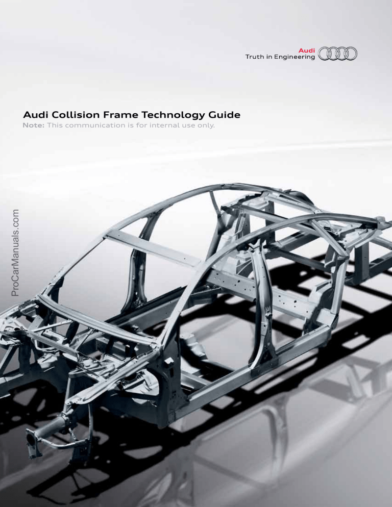
Audi Collision Frame Technology Guide ProCarManuals.com Note: This communication is for internal use only. Introduction The Audi Collision Frame Technology Guide is designed to serve the following reference needs: ProCarManuals.com Audi Authorized Collision Repair Facilities will use the guide to identify the components and procedures required for each repair. This information is critical to ordering the correct parts and repair materials, using the correct equipment (welders, bench systems, etc.) and making accurate estimates based on this criteria. Insurance estimators will find the guide invaluable for verifying the accuracy of estimates and recognizing the unique qualifications of Audi Authorized Collision Repair Facilities in effecting safe, structurally sound and aesthetically satisfying repairs. NOTE: This guide is NOT a repair manual and is intended for informational purposes only. Contents Technical Service Bulletins 2022005 3 00 Structural body damage or body dimensions differ from Repair Manual specifications ATE-09-40 5 Special Tools and Equipment: Audi Approved Spot Welders Steel Vehicles ProCarManuals.com Audi A3 2006 A3 9 Audi A4 2009 A4 11 Audi A5 2008 A5/S5 12 2010 A5 Cabriolet 17 Audi A6 2005 A6 18 2012 A6 20 Audi Q5 2009 Q5 21 Audi Q7 2007 Q7 24 Aluminum Vehicles Audi A7 2012 A7 27 Audi A8 2011 A8 30 Audi R8 2009 R8 31 Audi TT 2008 TT 32 Technical Service Bulletins Topic 00 Structural body damage or body dimensions differ from Repair Manual specifications Market area United States 444 Volkswagen of America, Inc. (6444), Canada 999 Volkswagen Canada Inc (6999) Brand Audi Transaction No. 2022005/1 Level EH Status Approval Release date ProCarManuals.com Customer codes ID Component group 041012 Damage group excessive wear/consumption/ damage Body Broad code Interior - pillars General code Detail code * * New customer code Object of complaint Body -> Structure Complaint type Position Dimensional accuracy Vehicle data All Audi Sales types Type MY Brand Designation Engine code Gearbox code Final drive code * 2005 A * * * * 2006 A * * * * 2007 A * * * * 2008 A * * * * 2009 A * * * * 2010 A * * * * 2011 A * * * * 2012 A * * * * 2013 A * * * * 2014 A * * * * 2015 A * * * Documents *True technical bulletin Document name master.xml Frame Technology Guide | 3 Technical Service Bulletins Condition Structural body damage or deviations from the body dimensions specified in the Repair Manuals are suspected and/or there is visible damage to structural components. ProCarManuals.com Technical Background Audi AG has defined structural damage as follows: Damage (dent, crack, buckling) and/or change in the position of a structural component of the vehicle body. Structural components refer to all components of the body except body shell components or components that are bolted on. However, bolted longitudinal members in aluminum vehicles are structural components. Online Resources • ElsaWeb is the online resource for Audi Dealers • Collision repair centers must use ErWin Service The vehicle must be placed on a repair bench system approved by Audi AG and measured. For a list of approved frame benches, refer to the Audi Authorized Collision Repair Facilities Required Tools and Equipment Guide. Warranty This TSB is informational only and not applicable to any Audi warranty. Repair Information Use the contacts below to access information that can aid you in the estimating and repair processes. Additional Information All parts and service references provided in this TSB are subject to change and/or removal. Always check with your Parts Department and Repair Manuals for the latest information. Elektron Tim Morgan [email protected] RAE David Gruskos [email protected] Tecna Bill Berman SBS Larry Nichol [email protected] (262) 656-5631 I-Car Steve Marks [email protected] (920) 749-0444 x131 Celette Bastien Dias Da Costa Car-O-liner Jeff Kern [email protected] (248) 624-5900 DuPont Rich Katko [email protected] (248) 583-5005 CarFax Sonya Halseth [email protected] (703) 934-2664 x4755 Sherwin Williams Rodes Brown [email protected] (804) 433-9690 Collision Advice Mike Anderson [email protected] (248) 909-0963 (386) 255-7090 (630) 369-6100 ©2011 Audi of America, Inc. All rights reserved. Information contained in this document is based on the latest information available at the time of printing and is subject to the copyright and other intellectual property rights of Audi of America, Inc., its affiliated companies and its licensors. All rights are reserved to make changes at any time without notice. No part of this document may be reproduced, stored in a retrieval system, or transmitted in any form or by any means, electronic, mechanical, photocopying, recording, or otherwise, nor may these materials be modified or reposted to other sites without the prior expressed written permission of the publisher. Frame Technology Guide | 4 Technical Service Bulletins Service Information Special Tools and Equipment Number: ATE-09-40 Subject: Audi Approved Spot Welders Date: Nov. 6, 2009 This is for U.S. Dealers only ProCarManuals.com Audi has approved three new spot welders for non-aluminum body repairs. These spot welders are the only factory-approved spot welders which carry the new Audi spot welding software programs and that meet Audi spot repair safety standards on MY 2009 and newer vehicles. It is a safety requirement that this tool standard be used when spot welding ultra-high-strength/advancedhigh-strength steel during collision repair as outlined in the Body Collision Repair Manuals. It is critical to note that only the spot welders carrying the VAS 6530, 6535 or 6545 designations contain Audi approved software and are upgradable for future programming changes as required. To verify that the shop you are referring collision repairs to uses the approved spot welders, access the lists of Audi Authorized Collision Repair Facilities. Refer to the Audi Top Service Process Guide (AccessAudi.com > Service tab > Audi Top Service Process Guide > Collision link > Body Collision link). Above the photo at the center of the page are two links. For all TT, A6, A7, A8, S8 and R8 models, click “Audi Authorized Aluminum Collision Network.” For all other models, click “Audi Authorized Collision Repair Facility Program.” Under the “Resources” menu at the right of the web page, the Audi Authorized Collision Repair Facility Program Manual 2010 and Audi Authorized Collision Repair Facility Program Manual list the approved spot welders (examples follow). Installation Note When using different types of steel and materials of different strengths, one of the resistance spot welders listed and approved by Audi is required to service them correctly under > Chapter “Special Tools.” The following pages provide details on each approved spot welder. Frame Technology Guide | 5 Technical Service Bulletins ProCarManuals.com Resistance Spot Welder VAS 6530 The VAS6530 Resistance Spot Welder is recommended for general body repairs on vehicles with high- and ultra-hightensile-strength steel panels, especially for workshops with a critical mains power supply. The inverter technology in conjunction with adaptive smart control makes quality spot weld joints possible. Variations in joint structure are detected and compensated for if possible. If a weld is not possible, a text warning message will be issued by the unit. Operation is by touch screen via three different welding modes: manual, smart/automatic or manufacturer-specific programs. With a USB interface, new welding programs can be uploaded or recorded; welding results can be copied for further processing on a PC. The water-cooled C-transgun delivers equal electrode contact force with electrode arms up to 635mm in length. Specifications: • Mains connection: 230V 3-Phase 60 Hz • Breaker protection: 60A delayed • Mains connection lead: 17 KVA • Welding current max.: 14,000 A DC • Electrode contact force max.: 450 daN (1,011 lbs.) • Dimensions: 600 mm (24") x 680 mm (27.2") x 1,220 mm (48.8") VAS 6530/1 Accessory Package • C-arm, long, 505 mm with angled electrodes, short (water-cooled) • C-arm, small, air-cooled for wheel housings with ball-head electrode • Ball-head electrode, water-cooled with mushroom head insert • Long, angled electrode, water-cooled • Weight: 130 kg (286 lbs.) VAS 6530/2 Accessory Package Includes: • C-arm, medium, 355 mm with angled electrodes, short (water-cooled) • Main unit with inverter and touch screen • Inverter C-transgun, pneumatic with short electrode • C-arm, length 85 mm with electrode, water-cooled • Cart with large wheels at rear and braked casters at front • Support, long for offset electrodes • Offset electrode, water-cooled • Long, straight electrode, water-cooled on arm side • C-Transgun holder and swivel arm with adjustable balancer Warranty: 24 Months • Water-cooler module for transformer, transgun, arms and electrodes Manufactured by: TECNA S.p.A. • Rubber mains power cord, 8 m on retractable stowage facility on cart • Electrode cap key for electrodes up to DN 21 Supplied by: Equipment Solutions 800-892-9650 Frame Technology Guide | 6 Technical Service Bulletins Resistance Spot Welder VAS 6535 ProCarManuals.com The resistance spot welder VAS 6535 features a central connection and a tool-detection function. An impedance measurement is used to regulate the welding parameters automatically. In this way, a constant level of quality of the weld points is assured. With VAS 6535, it is possible to store the weld processes and to document them. Disturbance variables such as dirt, adhesive, etc., are detected and compensated for. A compact flash memory card allows the unit’s software to be updated at any time. Mobile resistance spot welder with inverter technology. Features impedance, measurement and welding parameter regulation. Specifications: • Mains connection: 208 – 240V 3-Phase • Mains connection lead ø/length: 6 mm2 / 10 m • Fuse protection at least: 60 A delay • Mains frequency: 60 Hz • Mains connection output: 42 kVA • Rated output at 50% ED: 60 KVA • Idle voltage max.: 23 V DC • Welding current regulated: max. 12,000 A DC VAS 6535 • Quick dent removal hammer • Linear balancer • Cooling unit • Heat exchanger • Special VAS Welding Programs VAS 6535/1 • Water tank volume: approx. 32 l/4.5 gal. VAS 6535/1 Accessory Package • Ambient temperature: 40 C° • Electrode set 02/06/415 MX coded • Type pf protection: IP21 • Electrode set 05 MX coded • Dimensions: 661 mm (26") x 661 mm (26") x 1,372 mm ( 54") • Electrode set 11/280 MX coded • Weight: 171 kg (376 lbs.) • Multi-purpose electrode SB8 for planishing work X Tongs: • Electrode caps A 13 R 25 (6 pcs.) • Cable length: 2.5 m • Electrode caps A 13 R 15 (6 pcs.) • Welding current: max. 12,000 A DC Warranty: 24 Months • Weight of tongs without cables: 8 kg Includes: • Mobile mains unit • X Tongs • Welding gun • Abrasive sponge, fine Manufactured by: Elektron, Bremen, Germany Supplied by: Equipment Solutions 800-892-9650 Frame Technology Guide | 7 Technical Service Bulletins Resistance Spot Welder VAS 6545 ProCarManuals.com Setting the welding parameters is carried out using simple, self-explanatory symbols. The welding programs are for high- and higher-tensile panels, for spot weld-bonded connections and for galvanized panels. Individual storage of welding parameters is possible. In addition, the system is suitable for documentation and administration of work order details on A4 paper. Software updates can be carried out using an SD card (upload). The material recognition function is performed with a material test program. Current control and pressure monitoring is provided. The welding process is monitored and the actual values are shown in the display. The C-arms can be exchanged by means of a quickpositioning feature. The C-arms can be opened via a folding catch, thereby enabling access to the body, for example, behind profile sections. VAS 6545 Specifications: • Power supply 3 x 190-240 Volt 50-60 Hz • Setting range 0-13 kA • Welding current: DC VAS 6545/1 VAS 6545/2 VAS 6545/3 • Continuous duty 100 %ED 2,8 kA • 1 CS transformer tongs with integrated C-arm size 1 • Open circuit voltage: 12 V DC • 1 balancer with spring-loaded cable • Max.Power with 5% ED: 156 KVA • 1 mounting set for C-arms • Fuse (slow blow): 63 A • Connector cable (Cu): 5m / 4 x 0,157sq inch) • Air pressure: 90 psi +/- 5% • Refrigerant: water + anti corr. • Water tank volume: 85 l / 22.5 gallon • Dimensions: 810 mm (32") x 560 mm (22") x 750 mm (30") • Welding lead length: 3,000 mm • Weight: 119 kg (262 lbs.) Includes: • Current source • 1 CS transformer tongs • 1 control unit with water tank 80 l Accessory Packs: VAS 6545/1 Transformer x-gun with water-cooling up to the tips. 3 x 200-240 Volt / 50-60Hz ≤ 13.000 A / 65 A breakers. VAS 6545/2 Single-sided gun for c-trafo air-cooled, with earth cable and accessory box on arm side VAS 6545/3 Single-sided gun for x-trafo air-cooled, with earth cable and accessory box. Warranty: 24 Months Manufactured by: Wielander & Schill Supplied by: Equipment Solutions 800-892-9650 Frame Technology Guide | 8 2006 Audi A3 Optimized Body ProCarManuals.com High-strength steel Ultra-high-strength steel Frame Technology Guide | 9 2006 Audi A3 (continued) Joining Techniques Laser Soldering Laser-solder joining achieves a better design and higher rigidity in the area of the invisible joint and trunk lid. Laser Welding Laser welding is used in areas which are not easily accessible. It increases chassis strength and rigidity while reducing deformation of the sheet metal. Plasma Soldering To ensure high rigidity and optimal design for the water channel, materials are joined by plasma soldering. ProCarManuals.com Spot Welding Crash-relevant and rigidity-defining joints are spot weld-bonded using a high-strength structural adhesive. Frame Technology Guide | 10 2009 Audi A4 Materials Ultra-high-strength steel Hot-formed (die-quenched) steel Aluminum ProCarManuals.com Mild steel High-strength steel Higher-strength steel Frame Technology Guide | 11 2008 Audi A5/S5 Materials Ultra-high-strength steel Ultra-high-strength hot-formed steel Aluminum ProCarManuals.com Mild steel High-strength steel Higher-strength steel Frame Technology Guide | 12 2008 Audi A5/S5 (continued) Repair ProCarManuals.com A5/S5 repair considerations New techniques are required for the repair of ultra-highstrength hot-formed steel. Straightening and reshaping of even minor deformations are not possible due to the high-tensile yield strength and the rebound effect of hotformed steel. A damaged component must be completely cut out and/or partially replaced in accordance with the manufacturer’s specifications. The use of butt welding to repair ultra-high-strength hotformed steel can cause weakness in the repair because of micro-structural changes arising from heating the steel during the welding process. To help ensure optimum repair integrity, suitable service solutions were incorporated during the development of the body structure that allow affected components to be replaced wholly or partially in special parting sections (depending on energy flow). Ultra-high-strength hot-formed steel This innovative material addresses the lightweight build and structural rigidity requirements of the new Audi line. It is used for the first time in multiple applications on the Audi A5/S5. Existing joining techniques have been modified to easily integrate the material into the vehicle production and repair processes. You will see it used even more extensively in future Audi vehicles. The A5/S5 body construction is a testimony to the experience of Audi in lightweight design and its knowledge of innovative welding and joining techniques. The benefits of these technologies is evident: • 38.8-lb. weight savings by using hot-formed steel • Component-specific joining techniques were developed • Tailored blanks of various wall thicknesses help increase overall body rigidity • Aluminum wings Frame Technology Guide | 13 2008 Audi A5/S5 (continued) Rewarding results These efforts have produced very high rigidity in addition to low body weight and a well-balanced axle load distribution. ProCarManuals.com For the occupants of the Audi A5/S5, this means a marked improvement in safety, agility and driving dynamics. Body vibration has also been reduced, bringing a further noticeable improvement in driving comfort. Repair concept of hot-formed steel Hot-formed steel is used in the following areas: • B-pillar • Rear inner sill • Rear longitudinal beam • Tunnel reinforcement • Tunnel bridge • Longitudinal beam reinforcement Upper B-pillar If the upper B-pillar (green) is damaged, the entire B-pillar must be replaced. Dealers should consult ElsaWeb, and collision repair centers should consult the ErWin Workshop Manual for replacement procedures. Special tools and workshop equipment are required. Frame Technology Guide | 14 2008 Audi A5/S5 (continued) ProCarManuals.com Lower B-pillar Repair is possible using a service part. The parting cut (circled) must be made as described for dealers on ElsaWeb and for collision repair centers in the ErWin Body Repair Manual. Lower area of B-pillar and rear inner sill panel Dealers should review repair procedures on ElsaWeb, and collision repair centers should consult the ErWin Workshop Manual. The extensive use of high-strength hotformed steel requires special welding equipment as well as welding accuracy. Material overheated in the welding process could fail in a future collision. Frame Technology Guide | 15 2008 Audi A5/S5 (continued) Rear longitudinal beam “Tailored blanks” are panels manufactured to size with different material thicknesses. As a tailored blank component, the rear longitudinal member was designed so that the ultra-high-strength section will only deform if major damage occurs to the surrounding body structure and straightening and reshaping are no longer possible. ProCarManuals.com High-strength steel Ultra-high-strength hot-formed steel Partial replacement of the rear longitudinal beam is possible. The parting cut must be made as described in the Workshop Manual on General Body Repairs. Frame Technology Guide | 16 2010 Audi A5 Cabriolet Materials Advanced high-strength steel Ultra-high-strength hot-formed steel ProCarManuals.com Mild steel High-strength steel Frame Technology Guide | 17 2005 Audi A6 Body ProCarManuals.com Spot-weld bonding Laser MIG soldering In addition to classic resistance spot welding, the following connecting techniques are used on the 2005 Audi A6 body shell: Laser-soldered zero joint Roof • Spot-weld bonding • Punch riveting • Clinching (hood and trunk openings) • Laser soldering • Laser welding • MIG soldering Outer side part Frame Technology Guide | 18 2005 Audi A6 (continued) Body Aluminum Hybrid component ProCarManuals.com High-tensile steel (180 - 300 N/mm2) Dual-phase steel (340 - 500 N/mm2) Special steel (600 - 900 N/mm2) Frame Technology Guide | 19 2012 Audi A6 Body Ultra-high-strength hot-formed steel Aluminum sheet Aluminum casting Aluminum extrusion ProCarManuals.com Mild steel High-strength steel Modern high-strength steel Ultra-high-strength steel The body of the 2011 Audi A6 shares the same platform as the Audi A7, which is of hybrid construction. The sheet-steel parts are of highstrength steel and ultra-high-strength steel. The diecast-aluminum strut mountings previously featured on the Audi A7 are used at the front end of the vehicle. Like in the 2005 Audi A6, the parcel shelf in the 2011 Audi A6 is made of sheet aluminum. On the 2011 Audi A6, attachments such as the hood, wings, doors and trunk lid are also made of sheet aluminum. Frame Technology Guide | 20 2009 Audi Q5 Materials 3.3% Ultra-high-strength steel 9.1% Ultra-high-strength die-quenched steel ProCarManuals.com 30.8% Mild steel 44.5% High-strength steel 12.3% Advanced high-strength steel Frame Technology Guide | 21 2009 Audi Q5 (continued) ProCarManuals.com Rear longitudinal beam, partially die-quenched B-pillar, partially die-quenched To optimize the performance of the B-pillar in a sideimpact collision, it is important that the lower section be able to absorb more deformation energy than the upper section – which, ideally, should have a very rigid construction. This was made possible, for example, in the 2009 Audi A4, through the use of tailored blanks. The B-pillar in the Audi Q5 is partially heated and then reshaped, as a result, the upper section of the pillar has properties of an ultra-high-strength die-quenched steel and the lower section those of an ultra-highstrength steel. This process is also applied to the rear longitudinal beams. Here, the rearmost section is able to absorb more deformation energy than the more rigid front section of this component. Frame Technology Guide | 22 2009 Audi Q5 (continued) ProCarManuals.com Partial replacement of side member/sill at inner front (defined cutting position, reinforcing required) B-pillar, weld seam Reinforcements, side member Cutting position, inner side member B-pillar, cutting position B-pillar, reinforcement The increased use of ultra-high-strength steels necessitates the use of body repair methods adapted specially to suit the properties of the materials. High-heat-input welding will irreversibly compromise the strength and structure of the component due to microstructural changes in the material. A body structure thus welded cannot, therefore, reliably meet the requirements. It is important to apply a very high contact pressure and a precision-controlled electrical current during spot welding work on ultra-high-strength die-quenched steels. Following extensive tests, modern spot-welding machines that meet precisely these requirements are now available through Workshop Equipment. MAG gasshielded arc welding may only be performed on these high-grade steels in specific areas, on a case-by-case basis. They are described in the workshop literature. After miscellaneous tests and crash simulations on repaired ultra-high-strength die-quenched steel body parts of the Audi Q5, Audi has approved two repair points at which MAG welding is permissible. Frame Technology Guide | 23 2007 Audi Q7 Materials 32% Higher-strength/ultra-high-strength steel 6% Aluminum ProCarManuals.com 36% Mild steel 26% High-strength steel Frame Technology Guide | 24 2007 Audi (continued) Joining Techniques ProCarManuals.com Spot-Weld Bonding Plasma Soldering Laser Soldering Frame Technology Guide | 25 ProCarManuals.com 2007 Audi Q7 (continued) Body Shell The high-strength body shell is made up of numerous materials joined together with ultramodern joining processes. Note: Some joining processes cannot be duplicated during collision repair or panel replacement. Always reference the body repair manual whenever collision repair or panel replacement is required. Laser Soldering A low-heat panel-joining process that does not melt the base metal, only the filler material, which is distributed between the surfaces of the joint. Creates a smooth joint and avoids melting the zinc corrosion protection. Laser soldering can be found at the roofpanel-to-side-panel joint. Squeeze-Type Resistance Spot Welding The most common type of panel attachment method is used throughout the vehicle. (Not shown.) Plasma Soldering Uses silicon bronze as filler wire to create a highquality joint. Like laser soldering, this is not a fusion process. It is more similar to adhesive bonding. Plasma soldering is used between the rain run channel and side panel. Spot-Weld Bonding Joining parts by spot welding through a layer of highstrength, electrically conductive structural adhesive. These areas are generally identified by a blue adhesive that can be seen behind the panel. Laser Welds Used to make tailor-welded blanks on the front lower longitudinal members. NOTE: A laser weld cannot be duplicated during the repair process and should not be used as a sectioning location. (Not shown.) Gas Metal Arc (GMA) or Metal Inert Gas (MIG) Welding GMA (MIG) welding is used quite extensively on the Audi Q7 body shell. There are several locations where GMA (MIG) stitch welds are used to join structural parts together. (Not shown.) Frame Technology Guide | 26 2012 Audi A7 Materials Ultra-high-strength steel Ultra-high-strength hot-formed steel Aluminum casting ProCarManuals.com Mild steel High-strength steel Advanced high-strength steel Frame Technology Guide | 27 2012 Audi A7 (continued) Materials Mild steel High-strength steel in B-pillars and side members Ultra-high-strength hot-formed steel ProCarManuals.com Aluminum sheet Aluminum casting Aluminum extrusion Body Structure Ultra-high-strength hot-formed components improve rigidity and crash safety. These components and assemblies are made from ultra-high-strength steel: • Front side member reinforcement • Bulkhead • A-pillar and roof frame side • B-pillar • Chassis rail (sill) • Front-seat crossmember • Tunnel reinforcement • Rear longitudinal member Body Attachments The front and rear bumper mounts, fenders, strut brace, doors and flaps are made of aluminum. B-Pillar Its component assembly is very hard at the top end and softer below a narrow transition zone. This enables side-impact forces to be absorbed effectively. Side Member Manufactured from two tailored blanks, the side member is high-strength sheet metal at the rear and ultra-high-strength hot-formed steel at the occupant cell. Both sheet metal blanks are butt-joined by a laser weld prior to forming. Frame Technology Guide | 28 2012 Audi A7 (continued) Structural integration of front end and strut mount Side member, top of wheel arch (fender stay) ProCarManuals.com Strut mount Adhesive Punch rivet Aluminum Castings The aluminum castings in the vehicle structure are joined to adjacent parts with punch rivets and structural adhesive. The adhesive between these two materials also acts as an insulator and prevents contact corrosion. This method of joining was also used on the 2007 Audi TT and 2011 Audi A8. Specific repair procedures have been developed for repairing damage to the aluminum castings and adjacent Side member, bottom parts, as well as straightening or reshaping of steel components and aluminum castings, which may not be easily detected. Reference For further information about punch riveting, refer to Self-Study Program 994703, The 2008 Audi TT Body. Frame Technology Guide | 29 2011 Audi A8 Materials Advanced-high-strength steel Ultra-high-strength hot-formed steel ProCarManuals.com Aluminum sheet Aluminum casting Aluminum extrusion ASF Body The body of the 2011 Audi A8 employs the proven Aluminum Space Frame (ASF) design. The structure is a composite of aluminum extrusions, aluminum castings, and aluminum sheet components. Audi uses 13 different grades of aluminum and several different grades of ultra-high-strength and advanced high-strength steel in the 2011 A8. Frame Technology Guide | 30 2009 Audi R8 Materials Aluminum extrusion Magnesium ProCarManuals.com Aluminum sheet Aluminum casting Frame Technology Guide | 31 2008 Audi TT Materials Aluminum extrusion Steel sheet (galvanized) ProCarManuals.com Aluminum sheet Aluminum casting Sill section Audi TT Four-chamber extruded section Sill section Audi A8 Three-chamber extruded section Frame Technology Guide | 32 ProCarManuals.com © 2011 Audi of America, Inc. “Audi,” “Truth in Engineering,” the four rings emblem, the Audi grille design and all model names are registered trademarks of AUDI AG. Printed in U.S.A. BR-11-430-US
