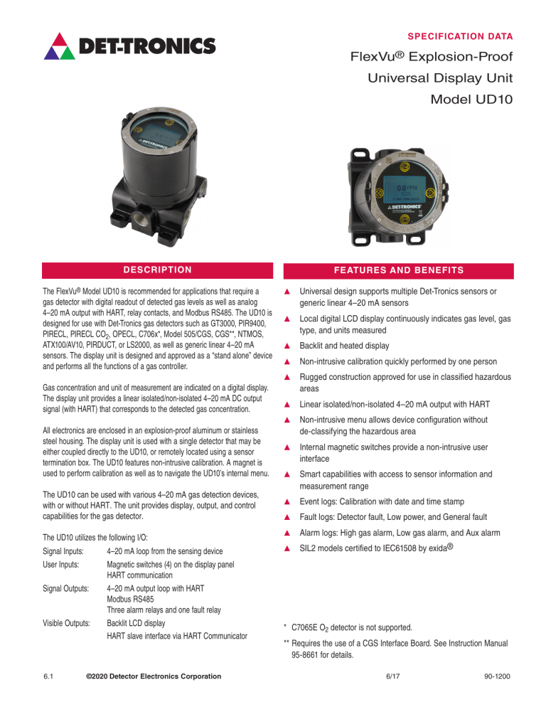
SPECIFICATION DATA FlexVu® Explosion-Proof Universal Display Unit Model UD10 DESCRIPTION The FlexVu® Model UD10 is recommended for applications that require a gas detector with digital readout of detected gas levels as well as analog 4–20 mA output with HART, relay contacts, and Modbus RS485. The UD10 is designed for use with Det‑Tronics gas detectors such as GT3000, PIR9400, PIRECL, PIRECL CO2, OPECL, C706x*, Model 505/CGS, CGS**, NTMOS, ATX100/AV10, PIRDUCT, or LS2000, as well as generic linear 4–20 mA sensors. The display unit is designed and approved as a “stand alone” device and performs all the functions of a gas controller. Gas concentration and unit of measurement are indicated on a digital display. The display unit provides a linear isolated/non-isolated 4–20 mA DC output signal (with HART) that corresponds to the detected gas concentration. All electronics are enclosed in an explosion-proof aluminum or stainless steel housing. The display unit is used with a single detector that may be either coupled directly to the UD10, or remotely located using a sensor termination box. The UD10 features non-intrusive calibration. A magnet is used to perform calibration as well as to navigate the UD10’s internal menu. The UD10 can be used with various 4–20 mA gas detection devices, with or without HART. The unit provides display, output, and control capabilities for the gas detector. The UD10 utilizes the following I/O: Signal Inputs: 4–20 mA loop from the sensing device User Inputs: Magnetic switches (4) on the display panel HART communication Signal Outputs: 4–20 mA output loop with HART Modbus RS485 Three alarm relays and one fault relay Visible Outputs: Backlit LCD display HART slave interface via HART Communicator 6.1 ©2020 Detector Electronics Corporation FEATURES AND BENEFITS S Universal design supports multiple Det-Tronics sensors or generic linear 4–20 mA sensors S Local digital LCD display continuously indicates gas level, gas type, and units measured S Backlit and heated display S Non-intrusive calibration quickly performed by one person S Rugged construction approved for use in classified hazardous areas S Linear isolated/non-isolated 4–20 mA output with HART S Non-intrusive menu allows device configuration without de‑classifying the hazardous area S Internal magnetic switches provide a non‑intrusive user interface S Smart capabilities with access to sensor information and measurement range S Event logs: Calibration with date and time stamp S Fault logs: Detector fault, Low power, and General fault S Alarm logs: High gas alarm, Low gas alarm, and Aux alarm S SIL2 models certified to IEC61508 by exida® * C7065E O2 detector is not supported. ** Requires the use of a CGS Interface Board. See Instruction Manual 95‑8661 for details. 6/17 90-1200 SPECIFICATIONS Operating Voltage Dimensions 24 Vdc nominal, operating range is 18 to 30 Vdc. Operating Power Dimensions shown in inches (centimeters). 6.48 (16.5) Standard model, with heater and backlight off: 3.46 (8.8) No alarm: Alarm: 1.5 watts @ 24 Vdc. 3 watts @ 24 Vdc (20 mA current output and all 3 alarm relays energized). Backlight on: 0.5 watt additional. Heater on: 3.5 watts additional. CGS model: Add 4 watts with CGS interface board and CGS sensor installed. 5.2 (13.2) 5.86 (14.9) Maximum power in alarm, with heater and backlight on: 7 watts @ 30 Vdc (Standard model) 11 watts @ 30 Vdc (CGS model) B2456 R0.175 NOTES: – Heater turns on when the internal temperature drops below –10°C. Heater function can be disabled to save power. Certification FM: – Appropriate relays will be activated when a fault or alarm occurs. FM Current Output Linear isolated 4–20 mA output with HART. Maximum loop resistance 600 ohms at 18 to 30 Vdc. Relay Contacts Three Alarm Relays: Form C, 5 amperes at 30 Vdc. Selectable energized/de-energized. Selectable latching/non‑latching. Storage Temperature –55°C to +75°C. Humidity Range 5 to 95% RH (Det-Tronics verified). Wiring Terminals 14 to 18 AWG, 2.5-0.75 mm2 wire can be used. CSA: CSA 08 2029512. Class I, Div. 1, Groups B, C & D (T5); Class I, Div. 2, Groups B, C & D (T4); Class II/III, Div. 1/2, Groups E, F & G. (Tamb = –55°C to +75°C) Type 4X Conduit seal not required. Performance verified in accordance with: CSA C22.2 #152. ATEX: 0539 II 2 G Ex d IIC T5 Gb Tamb –50°C* to +75°C FM08ATEX0042X IP66 Performance verified in accordance with: EN 60079-29-1:2007 and EN 60079-29-4:2010 ® APPROVED Conduit Entries 3/4" NPT or M25. Enclosure Material F M steel. Epoxy coated aluminum or 316 stainless Class I, Div. 1, Groups B, C & D (T5); Class I, Div. 2, Groups B, C & D (T4); Class I, Zone 1/2 AEx d IIC (T5); Class II/III, Div. 1/2, Groups E, F & G. Tamb –50°C* to +75°C NEMA/Type 4X, IP66 Conduit seal not required. Performance verified in accordance with: ANSI/ISA-92.00.01 ANSI/ISA-12.13.01 (CGS excluded) FM 6310/6320 ANSI/ISA-12.13.04/FM 6325 FM –55°C to +75°C. ® APPROVED One Fault Relay: Form C, 5 amperes at 30 Vdc. Normally energized for no fault condition with power applied. Operating Temperature 4.7 (11.9) APPROVED Shipping Weight Aluminum: Stainless Steel: Warranty 12 months from date of installation or 18 months from date of shipment, whichever occurs first. Electro-Magnetic Compatibility EMC Directive 2004/108/EC EN55011 (Emissions) EN50270 (Immunity). 4.15 pounds (1.88 kilograms). 10.5 pounds (4.76 kilograms). ® FM ® APPROVED IECEx: Ex d IIC T5 Gb Tamb –50°C* to +75°C IECEx FMG 08.0010X IP66 Performance verified in accordance with: IEC 60079-29-1:2007 SIL: All safety certified UD10 models are SIL2 certified per IEC61508 Refer to Instruction Manual 95-8661 for in-depth information regarding the FlexVu UD10 Universal Display Unit. *UD10 hazardous location and performance testing was successfully completed down to –55°C, however, the FM approved rating is limited to –50°C because there are no conduit fittings, cables, or cable glands that are presently listed for use below –50°C in the U.S. FM approvals policy does not allow product temperature ratings to exceed required installation components (such as conduit seals). The user must ensure that conduit fittings, cables, cable glands, etc., are rated for the expected minimum ambient temperature of the installation. Specifications subject to change without notice. All trademarks are the property of their respective owners. © 2020 Detector Electronics Corporation. All rights reserved. Det-Tronics manufacturing system is certified to ISO 9001— the world’s most recognized quality management standard. ­Corporate Office 6901 West 110th Street Minneapolis, MN 55438 USA www.det-tronics.com Phone: +1 952.941.6665 Toll-free: +1 800.765.3473 Fax: 952.829.8750 [email protected]

