item referencia descripción cant. 1 g2 generador ii con
Anuncio
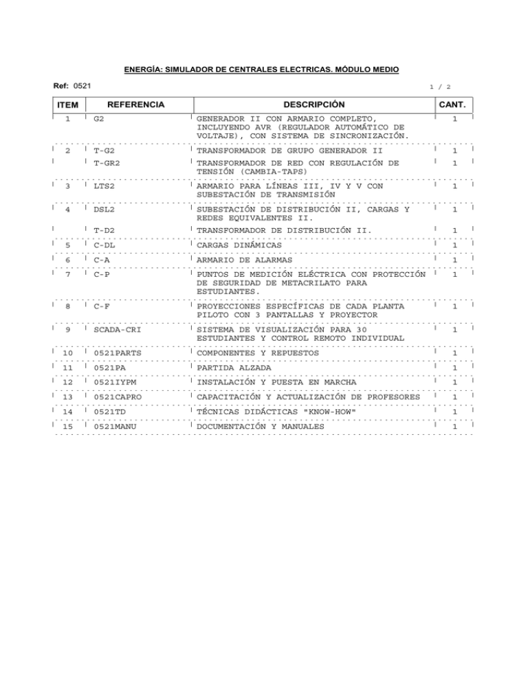
ENERGÍA: SIMULADOR DE CENTRALES ELECTRICAS. MÓDULO MEDIO Ref: 0521 1 / 2 REFERENCIA ITEM DESCRIPCIÓN CANT. 1 G2 GENERADOR II CON ARMARIO COMPLETO, INCLUYENDO AVR (REGULADOR AUTOMÁTICO DE VOLTAJE), CON SISTEMA DE SINCRONIZACIÓN. 1 2 T-G2 TRANSFORMADOR DE GRUPO GENERADOR II 1 T-GR2 TRANSFORMADOR DE RED CON REGULACIÓN DE TENSIÓN (CAMBIA-TAPS) 1 3 LTS2 ARMARIO PARA LÍNEAS III, IV Y V CON SUBESTACIÓN DE TRANSMISIÓN 1 4 DSL2 SUBESTACIÓN DE DISTRIBUCIÓN II, CARGAS Y REDES EQUIVALENTES II. 1 T-D2 TRANSFORMADOR DE DISTRIBUCIÓN II. 1 5 C-DL CARGAS DINÁMICAS 1 6 C-A ARMARIO DE ALARMAS 1 7 C-P PUNTOS DE MEDICIÓN ELÉCTRICA CON PROTECCIÓN DE SEGURIDAD DE METACRILATO PARA ESTUDIANTES. 1 8 C-F PROYECCIONES ESPECÍFICAS DE CADA PLANTA PILOTO CON 3 PANTALLAS Y PROYECTOR 1 9 SCADA-CRI SISTEMA DE VISUALIZACIÓN PARA 30 ESTUDIANTES Y CONTROL REMOTO INDIVIDUAL 1 10 0521PARTS COMPONENTES Y REPUESTOS 1 11 0521PA PARTIDA ALZADA 1 12 0521IYPM INSTALACIÓN Y PUESTA EN MARCHA 1 13 0521CAPRO CAPACITACIÓN Y ACTUALIZACIÓN DE PROFESORES 1 14 0521TD TÉCNICAS DIDÁCTICAS "KNOW-HOW" 1 15 0521MANU DOCUMENTACIÓN Y MANUALES 1 Ref: 0521 ITEM 2 / 2 REFERENCIA DESCRIPCIÓN Notas: a)Opción de multipuesto: * Este módulo tiene una unidad solamente en cada item, nosotros podemos recomendar el número de unidades para que 10 o 30 estudiantes puedan trabajar simultáneamente. b)Condiciones de suministro: * Condiciones técnicas: - Adaptación de los laboratorios. - Instalación de todos los equipos. - Puesta en marcha de todos los equipos. - Entrenamiento de cada uno de los ejercicios a ser realizados con cada uno de los equipos. - Formación de profesores, relacionada con cada equipo didáctico y cada una de las técnicas de enseñanza aplicada. - Transferencia de tecnología. * Condiciones comerciales: - Embalaje. - Gastos de financiación. - Gastos C.I.F. * Otras condiciones: - 8 Manuales para cada uno de los equipos didácticos de EDIBON: . Manual de servicios requeridos. . Manual de montaje e instalación. . Manual de la interface y del software/consola de control. . Manual de puesta en marcha. . Manual de normas de seguridad. . Manual de prácticas. . Manual de mantenimiento. . Manual de calibración. Ver catálogos en las páginas siguientes CANT. 5.2- Energy Power Plants PSS12. Complete Power Plant Simulator: Generation, Transformation, Transport, Distribution and Consumption. (SCADA control system included) PSS12: Complete Configuration (14 Units). 1AG1. Generator Unit 3AT3. Power Transformer 4AL4. Substation and Lines Cubicle 5AC5. Loads and Network Equivalents Cubicle 8BCE1. Electric Control Desk 6BEN1. Electric Control Board 1 (Energy Generation) 7BEL1. Electric Control Board 2 (Transformation and Lines) 5.- Energy Basic Configuration = Mini PSS12. Power Plant Simulator: Generation, Transformation, Transport, Distribution and Consumption (7 Units). 2AG2. Generator and Auxiliary Services Cubicle 9BPR2. Electric Control Board 3 (Spare) 11CEP1. Energy Control Desk with SCADA System included 10CVW1.Videowall 12DAD1./13DAD2./14DAD3. Control Boards (slides) More information in: www.edibon.com/products/catalogues/en/units/energy/energypowerplants/PSS12.pdf Page 75 www.edibon.com 5.2- Energy Power Plants (continuation) PSS12. Complete Power Plant Simulator: Generation, Transformation, Transport, Distribution and Consumption. (SCADA control system included) (continuation) SPECIFICATIONS SUMMARY SOME PRACTICAL POSSIBILITIES General Possibilities Example for Hydroelectric Power Plant: Experiments for Simulator Knowledge: EXPERIMENTS FOR SIMULATOR KNOWLEDGE (ESK) ESK 1. Simulated Hydroelectric Power Station. 1) Specific study of Simulator behaviour. 1.1. General description. 1.2. Layout. ! The selection of one type of Power Plant or another one will make the 1.3. Main wiring diagram. system to behave according to a specific simulation. 1.4. One-line electrical schema. ! The Simulator carries out a complex mathematical modelling that will 1.5. Mosaic type structure diagrams. allow studying the real behaviour of the Power Plant during the primary 1.6. Unit Steady States (USS). energy conversion. 1.7. Procedures for Unit Starting (PUS) and Shut Down (PUD). ! All Power Plant parameters can be edited allowing to modify and 1.8. Electrical and Hydraulics conditions for USS ,PUS and PUD. 1.9. Operation modes. adequate to specific Power Plants cases. For example, in the Hydroelectric ESK 2-6. Overall presentation of simulation models: type: rain amount, affluents, pipes, bumpy textures, etc. ESK 2. Model of the Energy Conversion in a Hydroelectric Power Station. ESK 3. Model of Generation Unit and Auxiliary Services. 2) Power Plant Control. All procedures. ESK 4. Model of Main Transformer, Substation and Interconnection Lines. ! Each different starting, operation and stop procedures belongs to each ESK 5. Model of Loads and Network Equivalent. specific Power Plant. ESK 6. Model of Control Room. ! During the process there will appear some images of real Power Plants ESK 7-22. Operation instructions for the different parts of the Equipment: ESK 7. Operations from Hydraulic Control Boards. while an animated simulation will show how our Power Plant works. ESK 8-10. Operations from Hydraulic Control Desk: ! It shows the real procedures that happens in a real Power Plant. ESK 8. Software operations on Hydraulic Control Desk: -Circuit Breaker Faults 3) Possibility to use different types of Power Plants at the same time. -Alarms ! Apart from the particular study of each type of Power Plant and the -………. ESK 9. Operation of Generator Excitation System from Hydraulic Control Desk. operation (generation) synchronized with the national electrical network, ESK 10. Operation of Power Electronic Converter from Hydraulic Control Desk. the simulator allows an interconnection between different types of Power ESK 11-12. Operations from Electric Control Boards: Plants. This will allow a real Network Simulation, studying the figure of ESK 11. Operations of the protective relays. system operator and regulating the combined operation of the different ESK 12. Other operations on the Electric Control Boards. Power Plants types. ESK 13-14. Operations from Electric Control Desk: ESK 13. Control and signalling of switchgear, taking into account interlockings. ESK 14. Generator frequency and voltage adjustments. Main Target ESK 15. Generator Unit. ESK 16-17. Operations on Generator and Auxiliary Services Cubicle: ! The main target of this Simulator is to train technical students, workers and ESK 16. Measurements of generator and auxiliary services quantities. even teachers, in how the Energy can be generated, transformed, transported, ESK 17.Location and type of fault selection for Synchronous generator protection distributed and how it can be consumed. system. ! Additionally PSS12 allows to simulate all the procedures carried out in real ESK 18. Power transformer. power plant to star up the generation plant, to run it and to connect it to the ESK 19-20. Operations on Substation and Lines Cubicle National grid (Electrical Network), etc. ESK 19. Adjustment of lines 1 and 2 lengths. ESK 20. Location and fault type selection on lines 1 and 2. ESK 21-22. Operations from Loads and Network Equivalents Cubicle ESK 21. Type and level of load selection. Structure of the Complete Simulator ESK 22. Network equivalents selection. ESK 23. Videowall. The Complete Simulator is formed by two main parts, the first part (a) with 14 Experiments for Operational Simulation: Units and the second one (b) the Simulation with Generation System Software Unit starting and shutdown procedures (EOS 1-17) EOS 1-14. Starting procedures. (Hybrid System). Starting unit to running in island- PUS 12 EOS 1. Manual starting. a) Small Scale Electric Power System: EOS 2. Guide-operator and automatic starting. This Small Scale Electric Power System consists of 14 different units (1AG1 Starting unit to running connected to network through Line 1- PUS 13. Generator Unit, 2AG2 Generator and Auxiliary Services Cubicle, 3AT3 EOS 3. Manual starting. Power Transformer, 4AL4 Substation and Lines Cubicle, 5AC5 Loads and EOS 4. Guide-operator and automatic starting. Starting unit to running connected to network through Line 1-PUS 13.2 Network Equivalents Cubicle, 6BEN1 Electric Control Board 1 (energy EOS 5. Manual starting. generation), 7BEL1 Electric Control Board 2 (transformation and lines), EOS 6. Guide-operator and automatic starting. 8BCE1 Electric Control Board 3 (spare), 9BPR2 Electric Control Desk, Starting unit to running connected to network through Line 1-PUS 13.3 10CVW1 Videowall, 11CEP1 Energy Control Desk, 12DAD1-13DAD2EOS 7. Manual starting. 14DAD3 Control Boards (slides)). EOS 8. Guide-operator and automatic starting. Starting unit to running feeding isolated loads through Line 1- PUS 14.1 This Complete Simulator is built with the same devices as those used in the EOS 9. Manual starting. EOS 10. Guide-operator and automatic starting. real Power Plants. Therefore the system reproduces at small scale the Starting unit to running feeding isolated loads through Line 2- PUS 14.2 functioning of a real Power System. EOS 11. Manual starting. EOS 12. Guide-operator and automatic starting. Not only the steps for starting a Power Plant, but many faults can be Starting unit to running feeding isolated loads through Lines 1 and 2- PUS 14.3 simulated. EOS 13. Manual starting. EOS 14. Guide-operator and automatic starting. EOS 15-17. Shutdown procedures b) Software Packages: Normal shutdown PUD-N 8 Software Packages, which allow to simulate 8 different Electric Power EOS 15. Manual shutdown. Plants, as follow: EOS 16. Guide-operator and automatic shutdown. ! Nuclear Power Station (ref. CN). Emergency shutdown PUD-E ! Diesel Thermal Station (ref. CTD). EOS 17. Emergency shutdown ! Fossil Fuel Thermal Station (ref. CTCF). Unit operating in normal regime (EOS 18- 58) EOS 18-29. Unit feeding isolated loads with automatic frequency control and voltage ! Combined Cycle Thermal Station (ref. CTCC). adjustment at remote substation busbars. ! Hydroelectric Station (ref. CHD). Through Line 1 (USS 4.1) ! Wind-powered Station (ref. CE). EOS 18. Determine voltage drop through line 1 with different pure resistive loads. ! Photovoltaic Solar Station (ref. CSFV). EOS 19. Determine voltage drop through line 1 with different pure inductive loads. ! Heliothermic Solar Station (ref. CHST). EOS 20. Determine voltage drop through line 1 with different pure capacitive loads. EOS 21. Determine voltage drop through line 1 with different mixed loads. Through Line 2 (USS 4.2) H and anyone requested by the customer. EOS 22. Determine voltage drop through line 2 with different pure resistive loads. EOS 23. Determine voltage drop through line 2 with different pure inductive loads. This is an Hybrid System as combines hardware and software using the proper EOS 24. Determine voltage drop through line 2 with different pure capacitive loads. mathematics models. EOS 25. Determine voltage drop through line 2 with different mixed loads. Through Lines 1 and 2 (USS 4.3) The final configuration of the Complete Simulator will be formed by: EOS 26.Determine voltage drop through lines 1 and 2 with different pure resistive 1) One small scale Electric Power System. loads. 2) At least, one of the eight Software Packages mentioned above. The EOS 27.Determine voltage drop through lines 1 and 2 with different pure inductive customer will decide which (any or all of them) of the software packages loads. wants to buy. EOS 28. Determine voltage drop through lines 1 and 2 with different pure capacitive loads. EOS 29. Determine voltage drop through lines 1 and 2 with different mixed loads. c) SCADA System. This unit uses a control and acquisition system (SCADA) EOS 30-33. Unit feeding isolated loads through Line 2 (USS 4.2) with automatic frequency in both versions MINI PSS12 and PSS12. control and voltage adjustment at substation bars. EOS 30. Determine voltage drop through main transformer with different pure resistive loads. More information in: www.edibon.com/products/catalogues/en/ ...Etc. (See PSS12 catalogue) units/energy/energypowerplants/PSS12.pdf 5.- Energy Differences between Simulators of the different Power Plants: Page 76
