Product Information · 03/2013
Anuncio
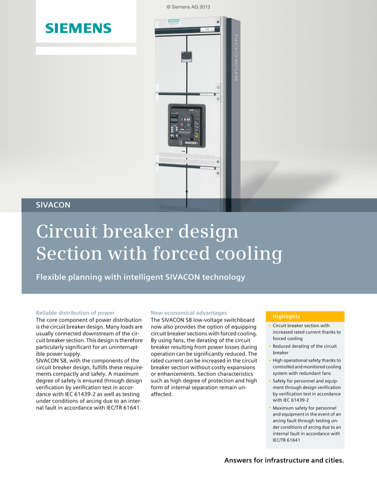
© Siemens AG 2013 s SIVACON Circuit breaker design Section with forced cooling Flexible planning with intelligent SIVACON technology Reliable distribution of power The core component of power distribution is the circuit breaker design. Many loads are usually connected downstream of the circuit breaker section. This design is therefore particularly significant for an uninterruptible power supply. SIVACON S8, with the components of the circuit breaker design, fulfills these requirements compactly and safely. A maximum degree of safety is ensured through design verification by verification test in accordance with IEC 61439-2 as well as testing under conditions of arcing due to an internal fault in accordance with IEC/TR 61641. New economical advantages The SIVACON S8 low-voltage switchboard now also provides the option of equipping circuit breaker sections with forced cooling. By using fans, the derating of the circuit breaker resulting from power losses during operation can be significantly reduced. The rated current can be increased in the circuit breaker section without costly expansions or enhancements. Section characteristics such as high degree of protection and high form of internal separation remain unaffected. Highlights 7 Circuit breaker section with increased rated current thanks to forced cooling 7 Reduced derating of the circuit breaker 7 High operational safety thanks to controlled and monitored cooling system with redundant fans 7 Safety for personnel and equipment through design verification by verification test in accordance with IEC 61439-2 7 Maximum safety for personnel and equipment in the event of an arcing fault through testing under conditions of arcing due to an internal fault in accordance with IEC/TR 61641 Answers for infrastructure and cities. © Siemens AG 2013 Switchboards SIVACON S8 Power Distribution Boards and Motor Control Centers Circuit breaker design Section with forced cooling ■ Overview Starting point Low-voltage switchboards are subject to continuously increasing technical requirements with high demands for personal and operational safety. This is manifested by a further increase in packing density associated with a high degree of protection for the system and a high form of internal separation. The rated currents in the switchboard increase. The operational power loss results in a higher development of heat. To reduce the temperature rise, it is possible to enlarge the cross-sections of the busbars. To improve the heat dissipation and cooling, section dimensions can be increased or the degree of protection and the form of internal separation reduced. However, these measures no longer satisfy the current demands placed on low-voltage switchboards. Innovative solution In SIVACON S8, the rated current in the circuit breaker section is significantly increased by means of forced cooling with fans. Costly upgrading and expansions are not required for this. The possible characteristics of the section are not restricted. By means of this patented innovative solution, SIVACON S8 satisfies the requirements placed on a modern low-voltage switchboard. Temperature rise in circuit breaker section without forced cooling Technical features • Optimally dimensioned cooling system • Effective cooling directly at the required positions • Four temperature-controlled, variable-speed fans • Factory-set control, no further settings required • Degree of protection possible up to IP54 • Internal separation possible up to form 4 • No restrictions for installation of devices • No space restrictions in the cabling box • Safety for personnel and equipment through design verification by verification test in accordance with IEC 61439-2 • Maximum safety for personnel and equipment through testing under conditions of arcing due to an internal fault in accordance with IEC/TR 61641 Cooling system with fans underneath the 3WL circuit breaker 2 Siemens · 2013 © Siemens AG 2013 Switchboards SIVACON S8 Power Distribution Boards and Motor Control Centers Circuit breaker design Section with forced cooling Function Principle • Cooling of the limiting measuring points detected in temperature-rise tests • Improved heat dissipation thanks to forced convection using additional heat sinks and a boosted, directional airflow using fans and ducts 1 Operational safety • Four regulated, monitored fans • Redundant safety concept • Failure of one fan has no effect on the rated current of the section • Emergency operation is possible should the complete cooling system fail • An alarm is output when a fan fails and/or if an impermissible temperature rise occurs • Factory-set fan control, no further settings required, incorrect parameterization impossible • Control voltage from power system, failure therefore only possible with interruption in line voltage • Use of long-life quality fans • Low temperature-controlled fan speed increases the service life 5 2 I201_18604 4 Maintenance All measures are incorporated in the maintenance concept for the switchboard. Checking and cleaning of fans and filter pads: • No change required in inspection intervals • Easy accessibility for maintenance and repair • Fan replacement possible during operation • Spare parts are available Other components of the cooling system are maintenance-free. 1 3 1 Filter (only for IP54) 2 Heat sink 3 Duct 4 Fan 5 Circuit breaker Functional principle of forced cooling ■ Benefits Reduction in derating Safe and user-friendly As a result of forced cooling with fans, the derating resulting from power losses during operation can be significantly reduced. The rated current in the circuit breaker section can be increased. This is possible without additional costs for larger busbar crosssections or a larger type of circuit breaker. The compact dimensions of the circuit breaker section are retained. Demands placed on the switchboard such as a high degree of protection or high form of internal separation are not restricted by the forced cooling. For high personal safety, in the case of the 3WL air circuit breaker in withdrawable design, the movement to the connected, test or disconnected position takes place with the door closed. The section dimensions are tailored to the size of the circuit breakers. Safety thanks to redundant cooling system The monitored cooling system of redundant design provides high operational reliability. Circuit breaker sections with forced cooling are completely integrated into the SIVACON S8 low-voltage switchboard system. Safety for personnel and equipment is ensured through design verification by verification test in accordance with IEC 61439-2 and testing under conditions of arcing due to an internal fault in accordance with IEC/TR 61641. The circuit breaker design provides optimum connection conditions for every rated current range. In addition to cable connections, the design also has design verification to be connected to SIVACON 8PS busbar trunking systems. The busbar trunking connection units specially developed for the SIVACON S8 are an integral component of the sections of the circuit breaker design. Siemens · 2013 3 © Siemens AG 2013 Switchboards SIVACON S8 Power Distribution Boards and Motor Control Centers Circuit breaker design Section with forced cooling ■ More information Maximum safety for personnel and equipment Requirements of standard IEC 61439 Design verification by testing Low-voltage switchboards or standard-compliant power switchgear and controlgear assemblies are developed, manufactured, and tested in accordance with the specifications of IEC 61439-2. In order to verify the suitability of the switchboard, this standard specifies two important types of verification – design verification and routine verification: • Design verifications are tests carried out during the development phase which have to be performed by the original manufacturer (developer). • Routine verifications are tests carried out on every manufactured switchboard which have to be performed by the manufacturer of the power switchgear and controlgear assembly prior to delivery. The SIVACON S8 low-voltage switchboard provides safety for personnel and equipment through design verification by verfification test in accordance with IEC 61439-2. The physical characteristics are designed in the test laboratory for operating and fault scenarios, and ensure a maximum degree of safety for personnel and equipment. The design verifications as well as the routine verifications are an important component of quality assurance, and are the prerequisites for assignment of the CE marking in accordance with EC directives and legislation. Verification of temperature rise One of the most important verifications in accordance with IEC 61439-2 is the "verification of temperature rise". The suitability of the switchboard with regard to temperature rise resulting from power losses is verified. This is one of the greatest challenges for switchboards due to the ever increasing rated currents along with higher demands for the degree of protection and for internal separation. In accordance with the standard, this verification can be carried out by calculation up to a rated current of 1600 A. Testing under conditions of arcing due to an internal fault An arcing fault is one of the most dangerous and far-reaching faults that can occur within switchboards, and can also damage adjacent outgoing feeders, sections or the complete system. Arcing faults can be the result of incorrect rating, reductions in insulation due to contamination, but also handling errors. The effects resulting from high pressure and extremely high temperatures can have fatal consequences for the operator and system, and even for the building. Testing of low-voltage switchboards under conditions of arcing due to an internal fault is a special test in accordance with IEC/TR 61641. SIVACON S8 provides verification of personal safety by means of testing under conditions of arcing due to an internal fault. With the SIVACON S8, verification is always carried out by testing. Rules for selection of the test samples (worst-case test) and testing of complete switchgear and controlgear assemblies ensure that the complete product range is systematically covered and that this verification always includes the devices. Testing of randomly selected samples is just as inadequate as replacing a device without renewed testing. Siemens AG Infrastructure & Cities Sector Low and Medium Voltage Division Medium Voltage & Systems Postfach 3240 91050 ERLANGEN GERMANY www.siemens.com/sivacon Subject to change without prior notice Order No.: E86060-K8210-E460-A1-7600 MP.R3.XT.0000.00.3.11 / Dispo 30403 PI 0413 1. SB 4 En Printed in Germany © Siemens AG 2013 The information provided in this catalog contains descriptions or characteristics of performance which in case of actual use do not always apply as described or which may change as a result of further development of the products. An obligation to provide the respective characteristics shall only exist if expressly agreed in theterms of contract. Availability and technical specifications are subject to change without notice. All product designations may be trademarks or product names of Siemens AG or supplier companies whose use by third parties for their own purposes could violate the rights of the owners.

![[ Graphics Card- 710-1-SL]](http://s2.studylib.es/store/data/005308161_1-3d44ecb8407a561d085071135c866b6c-300x300.png)
