VG200 - CPS Products
Anuncio
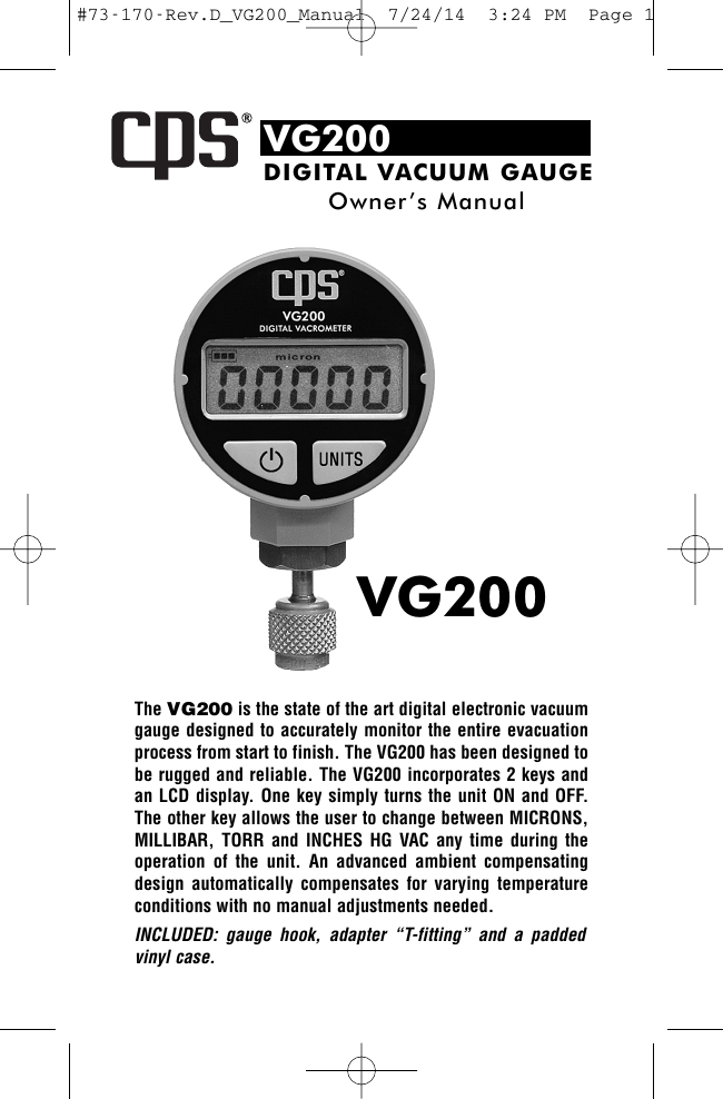
#73-170-Rev.D_VG200_Manual 7/24/14 3:24 PM Page 1 VG200 DIGITAL VACUUM GAUGE Owner ’s Manual VG200 The VG200 is the state of the art digital electronic vacuum gauge designed to accurately monitor the entire evacuation process from start to finish. The VG200 has been designed to be rugged and reliable. The VG200 incorporates 2 keys and an LCD display. One key simply turns the unit ON and OFF. The other key allows the user to change between MICRONS, MILLIBAR, TORR and INCHES HG VAC any time during the operation of the unit. An advanced ambient compensating design automatically compensates for varying temperature conditions with no manual adjustments needed. INCLUDED: gauge hook, adapter “T-fitting” and a padded vinyl case. #73-170-Rev.D_VG200_Manual 7/24/14 3:24 PM VACUUM LEVEL INDICATORS Atmospheric Pressure to 25” hg vac -Indicated by the top bars are energized. Pressure between 25” hg vac to 100,001 microns -Indicated by the top, middle bars are energized. Pressure between 100,000 and 76,001 microns -Indicated by the top, middle and bottom bars energized Pressure between 76,000 to 50,001microns -Indicated by the middle and bottom bars are energized. Pressure between 50,000 and 25,001 microns -Indicated by the bottom bars energized Pressure between 25,000 microns and 0 microns -Displayed as a number on the LCD display OPERATION The versatility of the VG200 design allows the technician to attach the unit in the following configurations: a) Connect directly to the service manifold gauge set (using the included “T-fitting”). b) Connect directly to the refrigerant system service ports (using the included “T-fitting”). c) Connect directly to one of the two of the refrigerant systems service ports. d) Connect directly to the vacuum pump (using the included “T-fitting”). e) Mount directly on to a 4 or 5 valve manifold. After attaching the VG200 in one of the above recommended configurations, depress the ON key to activate the unit. Upon start up, the LCD will display the software version number. Once the LCD displays a moving cursor or vacuum level, depress the unit’s key until the desired units or measure are shown. Next, initiate the evacuation process (start vacuum pump) and monitor the VG200 until the desired micron level is achieved. Page 2 #73-170-Rev.D_VG200_Manual 7/24/14 3:24 PM BATTERY INDICATOR (with BAR GRAPH power level indicator) The battery indicator is shown on the LCD as a battery shape with a 3 segment Power Level Bar Graph: 100% ( 3 segments ) of Bar Graph67% ( 2 segments ) of Bar Graph33% ( 1 segment ) of Bar Graph0% ( 0 segments ) of Bar GraphDashes across the Display- Battery at 100% to 80% Battery at 80% to 60% Battery at 60% to 20% Battery at 20% to 5% Battery below 5%, replace Note: If the Low Battery indicator cannot be resolved with a new battery, See Sensor Maintenance section. VACUUM PUMP CHECK Contaminants quickly form in the oil of a vacuum pump. The contaminated oil can severely inhibit the performance of a pump and eventually cause damage to the pump itself. The VG200 incorporates a unique vacuum pump check designed to test the performance of a vacuum pump BEFORE it is used to evacuate a system. Simply attach the VG200 directly to the vacuum pump and watch the display as it measures the performance of the vacuum pump. Note: Different sizes and brands of vacuum pumps will experience varied results. Check the specifications published by the manufacturer of your vacuum pump to determine the ultimate vacuum level your pump can achieve. Many published specifications state that pumps rated between 2 & 8 CFM should experience an ultimate vacuum between 15 and 50 microns. SENSOR MAINTENANCE Note: If the Low Battery indicator does not de-energize after replacing with a brand new battery, the VG200 sensor is saturated with Oil or other contaminants. Please proceed with the cleaning processing below. Page 3 #73-170-Rev.D_VG200_Manual 7/24/14 3:24 PM Page 4 The VG200 incorporates an easy to clean thermistor sensor, which cannot be damaged from exposure to positive pressure or oil mist. To clean the VG-200’s thermistor sensor, simply invert the unit and pour approximately 1 tablespoon of 100% DENATURED ALCOHOL directly into the sensor housing. Gently shake the unit to produce a swirling effect of the cleaning solution in the housing. Then, pour the remaining cleaning solution out. Repeat this procedure until the alcohol appears to be clean and clear of oil when removed from the sensor housing. Then, allow the sensor to air dry (DO NOT BLOW DRY). Check the gasket located inside the nut during sensor maintenance. If the gasket appears to be torn or deformed, replace it with a new gasket (CPS P/N:HXG, includes 10 replacements). SPECIFICATIONS SENSOR: TYPE: Self-heated thermistor bridge with integral temperature compensation from 0 to 50 °C (32 to 122 °F). OPERATING PRESSURE RANGE: Atmospheric pressure to 0 microns Maximum Working pressure: 600 PSIG BURST PRESSURE: 3000 PSIG OPERATING RANGE: Atmospheric to 0 microns ACCURACY: +/- 10% of Reading. OPERATING TEMPERATURE RANGE: Compensated (accuracy as stated): 0°C TO 50°C (32°F TO 122°F) Non-compensated (add +/- 0.5% error for every °C outside compensated range): 0 to 50°C (-22 to 158°F) OPERATING & STORAGE HUMIDITY: 0-95%, non-condensing. STORAGE TEMPERATURE: -40 to 85°C (-40 to 185°F) POWER SOURCE: One 9 volt alkaline battery (ANSI 1604AC – IEC 6LR61) BATTERY LIFE: 20 hours of continuous use. Instrument shuts itself off after 5 minutes of operation. WEIGHT: 153 g. (5.5 oz.) excluding the battery. DIMENSIONS: 68 mm. diameter by 40 mm. deep by 124 mm. overall height (2.7” dia. by 1.6” deep by 5” overall height). MECHANICAL CONNECTION: Standard 1/4” female SAE refrigerant hose type with core depressor. BATTERY INDICATOR: Battery symbol with 3 segment Power Level Bar Graph. #73-170-Rev.D_VG200_Manual 7/24/14 3:24 PM Page 5 VG200 VAC U O M E T R E D I G I TA L VG200 Le VG200 est un vacuomètre extraordinaire, conçu pour contrôler avec grande justesse le procès d’évacuation du début à la fin. Le VG200 est un appareil rigide et fiable. Deux touches et un écran LCD garantissent une opération facile. Une touche est pour la mise en marche, l’autre pour choisir entre MICRONS, MILLIBAR, TORR et POUCES HG VAC, même pendant l’opération. Un compensateur automatique ajuste les mesures en cas de changements de températures ambiantes. Inclus: crochet et adaptateur T dans une pochette en vinyl. #73-170-Rev.D_VG200_Manual 7/24/14 3:24 PM INDIQUATEUR DU NIVEAU DE VIDE Pression atmosphérique jusqu’à 25”hg vac -Indiqué par toutes les barres. Pression entre 25’’hg et 10,001 microns -Indiqué par les barres du haut et du centre. Pression entre 100,000 et 76,001 microns -Indiqué par les barres du haut, le centre et le bas Pression entre 76,000 et 50,001 microns -Indiqué par les barres du centre et du bas. Pression entre 50,000et 25,001 microns -Indiqué par les barres du bas Pression entre 25,000 et 0 microns -Indiqué par un chiffre à l’écran LCD OPERATION Le VG200 peut être utilisé dans différentes combinaisons: a) Connection directe sur le manifold (utilisant le connecteur «T»). b) Connection directe sur la vanne de service de l’unitée a controller (utilisant le connecteur “T”). c) Connection directe sur la pompe à vide (utilisant le connecteur “T”). d) Montage direct sur un manomètre a 4 / 5 valves. Après avoir connecté le VG200 dans une des configurations mentionnées çi-dessus, allumer par la touche ON. Au départ l’écran affichera le numéro de la logicielle, puis, choisissez l’unité de mesure préféré. Allumez la pompe à vide et contrôlez le niveau jusqu’à ce que le niveau nécessaire est obtenu. Page 6 #73-170-Rev.D_VG200_Manual 7/24/14 3:24 PM Page 7 INDIQUATEUR DE BATTERIE (par 3 segments indiquateurs) 100% ( 3 segments )67% ( 2 segments )33% ( 1 segment )0% ( 0 segments )clignotant- Batterie Batterie Batterie Batterie Batterie entre 100% et 80% entre 80% et 60% entre 60% et 20% entre 20% et 5 % morte, remplacer Remarque : si le changement de batterie ne résoud pas le problème de ’indication du niveau de charge, consultez le paragraphe de la maintenance du sensor. CONTROLE DE POMPE A VIDE L’huile de la pompe à vide peut être rapidement contaminé. Cette contamination peut réduire considérablement les performances et éventuellement causer de dégâts à la pompe. Le VG200 est muni d’un système unique qui permet de controler les performance de la pompe, AVANT l’évacuation du système. Ceci simplement en connectant le VG200 directement sur la pompe. L’écran indiquera les performances de la pompe. MAINTENIR LE SENSOR Remarque: Au cas où, après avoir changé la batterie, l’indicateur de charge ne se remet pas a son nieveau initial, le sensor du VG200 est saturé d’huile ou autres contaminants. Procedez au nettoyage du sensor comme décrit dans le manuel. Le VG200 possède un sensor thermistor indifférent à la pression positive ou vapeur d’huile. Pour rincer l’unité, simplement décrocher, retourner et verser une cuillère d’alcol dans l’ouverture du VG200. Secouer lentement le tout, afin de rincer à l’intérieur. Déverser. Répéter cette opération jusqu’à ce que l’huile déversée reste claire. Puis laisser sècher à l’air ambiante (ne pas utiliser de l’air comprimé). Contrôler l’état du joint à l’intérieur du VG200. En cas de d éformation, remplacer le joint ( l’article HXG comprends 10 joints de remplacement) #73-170-Rev.D_VG200_Manual 7/24/14 3:24 PM SPECIFICATIONS SENSOR: Type: Thermistor auto-chauffant avec compensateur de température de 0 a 50 °C Pressions d’opération: Pression atmosphérique à 0 microns. Pression maximale d’usage: 600 PSIG Pression déclatement: 3000PSIG OPERATING RANGE: Atmospheric to 0 microns PRÉCISION: +/- 10% de la lecture. TEMPERATURE D’OPERATION: Compensé: 0°C a 50°C Non-compensé: ajoutez +/- 0.5% a chaque °C Entre 0° et 50°C HUMIDITE: De 0 a 90% (non-condensé) TEMPERATURE DE STOCKAGE: 40 a 85°C (-40 a185°F) COURANT: 1 x 9 Volt batterie, alcaline BATTERIE: 20 heures continu, auto-arrêt après 5 minutes d’inactivité POIDS: 153g sans batteries DIMENSIONS: 68 mm. diametre de 40 mm. sur 124 mm. de haut. CONNECTION MECHANIQUE: 1/4 femelle SAE avec dépressuer. INDICATEUR DE BATTERIE: Symbole de batterie à 3 segments. Page 8 #73-170-Rev.D_VG200_Manual 7/24/14 3:24 PM Page 9 VG200 DIGITAL VAKUUM MANOMETER Anleitungen VG200 Die VG200 ist eine Entwicklung auf dem neuesten Stand der Technik. Das Design und die äußerst genaue Anzeige zeichnet dieses Gerät besonders aus.Die VG200 beinh altet 2 Schaltmöglichkeiten und 1 LCD Display. Mit dem einen Schalter schalten Sie das Gerät “EIN und AUS” Mit dem anderen Schalter ändern Sie die Meßangaben von MICRONS, MILLIBAR, TORR und INCHES HG VAC zu jeder Zeit, auch während der Messungen. Ausgestattet mit einer besonders vorteilhaften Umgebungsanpassung und den unterschiedlichsten Temperaturanpassungen. Keine manuellen Einstellungen erforderlich. Lieferumfang: Haken für Manometer, Adapter als “T - Stück” und gepolsterte Tasche. #73-170-Rev.D_VG200_Manual 7/24/14 3:24 PM ALLGEMEINE BEDIENUNG Die vielseitige Anwendungsmöglichkeit der VG200 erlaubt es dem Anwender dieses Gerät unterschiedlich anzuschließen. a) Anschluß direkt an der Prüfarmatur am ND Manometer mit dem beigefügten T-Stück. b) Anschluß direkt an dem Kältesystem – Serviceanschluß mit dem beigefügten T-Stück. c) Anschluß direkt an dem einen von beiden Kältesystem – Serviceanschluß. d) Anschluß direkt an der Vakuumpumpe mit dem beigefügten T-Stück. e) Aufgeschraubt direkt an der 4 – oder 5 – Ventil Prüfarmatur. Nachdem Sie die VG200 gemäß von einen der vorgenannten Möglichkeiten aufgeschraubt haben, drücken Sie die ON – Taste um das Gerät einzuschalten. Auf der LCD lesen Sie zuerst die Versions-Nr. Sobald auf dem Display die ersten Werte eines Vakuums zu erkennen sind, drücken Sie die UNITS – Taste bis zur gewünschten Druckein-heit. Schalten Sie die Vakuumpumpe ein und beobachten weiterhin den Vakuumablauf bis das gewünschte Vakuum erreicht worden ist. BATTERIE - LADEZUSTANDSANZEIGE Der Batterie - Ladezustand ist auf dem LCD mit 3 möglichen Segmentenzu erkennen. 100% (3 segmente) - auf der Anzeige 67% (2 segmente) - auf der Anzeige 33% (1 segment) - auf der Anzeige 0% (0 segment) - auf der Anzeige Strich durch die Anzeige Batterie ca. 100% bis 80% Batterie ca. 80% bis 60% Batterie ca. 60% bis 20% Batterie ca. 20% bis 5 % Batterie unterhalb von 5% ANMERKUNG: Falls nach dem Wechsel einer neuen Batterie die Batterie-Ladezustandsanzeige keine Reaktion zeigt, bitte verfahren Sie nochmals wie unter “SENSOR Instandhaltung bzw. Wartung” Page 10 #73-170-Rev.D_VG200_Manual 7/24/14 3:24 PM Page 11 VAKUUMPUMPE ÜBERPRÜFEN Überprüfen Sie das Öl in der Vakuumpumpe. Schmutziges, oder sehr altes Öl kann zu erheblichen Leistungs-minderungen führen und nicht selten zu Beschädigungen an der Pumpe. Bevor Sie ein System vakuumieren, überprüfen Sie erst die Leistungsfähigkeit der Vakuumpumpe. Schrauben Sie die VG200 direkt auf dem Saugstutzen der Vakuum- pumpe und beobachten auf dem Display ob das erforderliche Vakuum erreicht wird. ANMERKUNG: Verschiedene Hersteller mit den unterschiedlichsten Pumpengrößen experimentieren mit den zu erreichenden Ergebnissen. Überprüfen Sie Angaben der Hersteller mit der VG200 um zu erkennen, ob diese Vakuumpumpe die erforderlichen, bzw. angegebenen Leistungen erreicht. SENSOR INSTANDHALTUNG BZW. WARTUNG ANMERKUNG: In dem vorliegenden Fall könnte es auch daran liegen, daß der Sensor mit einem Ölnebel, oder einer anderen Art der Verschmutzung gesättigt ist. Bitte verfahren Sie dann wie unter dem gleichen vorgenannten Punkt, hier jedoch unter “Reinigung des Thermistor Sensors” Die VG200 beinhaltet einen leicht zu reinigenden Thermistor Sensor. Dieser Sensor ist äußerst unem-pfindlich und kann weder durch plötzlichen Druck, noch durch Ölnebel beschädigt werden. Zum Reinigen des Thermistor Sensors gehen Sie wie folgt vor: Drehen Sie das Gerät um und schütten ca. 1 Eßlöffel ALCOHOL direkt in das Sensor-Gehäuse. Leichtes schütteln erzeugt einen wirbelnden Effekt zur Reinigung von dem Gehäuse und dem Sensor. Schütten Sie anschließend diese Flüssigkeit wieder aus. Wiederholen Sie diesen Vorgang solange, bis der Alkohol klar bleibt und alles Öl aus dem Gehäuse heraus ist. Erlauben Sie danach den Sensor an der Luft zu trocknen (Nicht mit Luftdruck blasen). Prüfen Sie die Dichtung in der inneren Seite von der Überwurfmutter während des Trocknungsvorganges. Sollte die Dichtung beschädigt, oder verformt sein, bitte unbedingt durch eine neue Dichtung (CPS Art.-Nr.: HXG, beinhaltet 10 Austauschdichtungen) austauschen. #73-170-Rev.D_VG200_Manual 7/24/14 3:24 PM SPEZIFIKATIONEN SENSOR TYPE: Selbstaufheizende Thermistor Brücke mit vollständiger Temperaturanpassung von 0 bis 50°C ARBEITSDRUCK: Atmosphärischer Druck bis 0 mbar Max. Arbeitsdruck: 41 bar BERSTDRUCK: 205 bar GENAUIGKEIT: ±10% vom Ablesewert. ARBEITSTEMPERATUR: Gleichbleibend 0°C bis 50°C Nicht gleichbleibend + / - 0.5 % Fehler für jedes °C außerhalb 0 °C bis 50°C ARBEITS - U. LAGERFEUCHTIGKEIT ( r.F.): 0 bis 95 % LAGERTEMPERATUR: - 40 °C bis 85 °C SPANNUNGSZUFUHR: 1 x 9 V Alkaline Batterie (ANSI 1604AC – IEC 6LR61) LEBENSDAUER DER BATTERIE: 20 h bei kontinuierlichem Gebrauch. Selbstabschaltung nach 5 Min. GEWICHT: 153 g. ohne Batterie ABMESSUNGEN: ø 68 mm. T: 40 mm. H: 124 mm ANSCHLUß: 1/4” SAE Innengewinde mit Ventildrücker BATTERIE-LADEZUSTANDSANZEIGE: 3 x Batteriesymbole mit 3 Segmenten Page 12 #73-170-Rev.D_VG200_Manual 7/24/14 3:24 PM Page 13 VG200 INDICADOR DIGITAL DE VACIO Manual De Operacion VG200 El modelo VG200 es un indicador digital de vacío diseñado para examinar el proceso de evacuación de principio a fin. El indicador ha sido diseñado para proveer la máxima confiabilidad y durabilidad. La operación se simplifica con el uso de un botón para apagar y encender el indicador y otro para cambiar de unidades entre MICRONES, MILIBARS, TORR y PULGADAS DE HG.; la pantalla LCD muestra todos los resultados en caracte res grandes, fáciles de leer. El instrum ento se ajustaautomáticamente de cara a los cambios de temperatura usando un sistema avanzado de compensación; no se requieren ajustes manuales. INCLUIDOS: batería, varilla de colgar, adaptador tipo “T” y una bolsa acolchada. #73-170-Rev.D_VG200_Manual 7/24/14 3:24 PM Page 14 INDICACION DE NIVEL DE VACIO Presión entre 25” Hg. vac a 100,001 micrones -Barra superior activada Presión entre 100,000 y 76,001 micrones -Barras superior y media activadas Presión entre 76,000 y 50,001micrones -Barras superior media e inferior activadas Presión entre 50,000 y 25,001 micrones -Barras media e inferior activadas Presión entre 25,000 micrones 0 micrones -Barra inferior activada OPERATION El diseño del modelo VG200 le permite al técnico utilizar con facilidad el instrumento de las siguientes maneras: a) Conectado directamente al manómetro de servicio usando el adaptador “T” b) Conectado directamente a la compuerta de servicio del sistema usando el adaptador “T” c) Conectado directamente a una de las dos compuertas de servicio del sistema d) Conectado directamente a la bomba de vacío usando el adaptador “T” e) Montado en un manómetro de servicio de 4 o 5 válvulas. Luego de haber instalado el VG200 de acuerdo a una de las maneras señaladas anteriormente, oprima el botón de encendido “ON”. Cuando el instrumento enciende, primero muestra la versión del programa. Una vez que las barras o los números se muestran en la pantalla, oprima el botón “UNITS” para seleccionar las unidades de la medición. Finalmente, encienda la bomba de vacío y observe la indicación en la pantalla del VG200 hasta lograr el nivel de vacío necesario. #73-170-Rev.D_VG200_Manual 7/24/14 3:24 PM Page 15 INDICADOR DE ESTADO DE BATERIA (indicador GRAFICO de potencia disponible) El indicador se muestra en la pantalla como el perfil de una batería con tres segmentos que indican el nivel de potencia disponible 100% (3 segmentos) de la gráfica de barraNivel de potencia de 100% a 80% 67% (2 segmentos) de la gráfica de barraNivel de potencia del 80% al 60% 33% (1 segmento) de la gráfica de barraNivel de potencia del 60% al 20% 0% (0 segmentos) de la gráfica de barraNivel de potencia del 20% al 5% Cinco rayas en la pantallaNivel de potencia debajo del 5%-REEMPLACE LA BATERIA PRUEBA DE LA BOMBA DE VACIO Con el uso, substancias contaminantes se forman rápidamente en el aceite de la bomba. Este aceite contaminado disminuye la efectividad de la bomba y puede llegar a dañarla. El diseño avanzado del VG200 le permite probar la bomba directamente ANTES de ser usada; conecte su VG200 directamente a la bomba y observe el nivel máximo de vacío que esta puede lograr. NOTA: Hay una gran diferencia entre las marcas de bombas de vacío; es preciso consultar las especificaciones de los fabricantes para determinar el máximo nivel de vacío de su bomba. Muchas de las especificaciones publicadas dicen que para bombas con un caudal de 2 a 8 CFM (pies cúbicos por minuto) el nivel de vacío debe llegar de 15 a 50 micrones. MANTENIMIENTO DEL SENSOR NOTA: Si el indicador de poder de bateria no se apaga despues de haber colocado una nueva bateria, entonces el sensor del VG200 esta saturado con aceite u otro contaminante. Favor de seguir con el procedimiento de limpieza segun abajo. El sensor del modelo VG200 es de construcción duradera y puede soportar presiones positivas y rocío de aceite sin consecuencias a dversas. Para limpiar el sensor basta echar una cucharada de ALCOHOL por la boca del sensor y agitarlo suavemente con movimiento rotatorio, vaciando el alcohol y repitiendo la operación cuantas veces sea necesario hasta que el líquido salga claro y libre de residuos de #73-170-Rev.D_VG200_Manual 7/24/14 3:24 PM Page 16 aceite. Finalmente, deje que el sensor se seque por evaporación natural del residuo de alcohol. Observe y cambie el sello de goma en la boquilla del sensor si este está gastado o deforme. NOTA: CPS No. HXG, incluye 10 repuestos. ESPECIFICATIONES SENSOR: TIPO: Puente de disipación térmica auto com pensado en el rango de 0 a 50 °C (32 a 122 °F). RANGO DE OPERACIÓN: Desde una atmósfera a 0 micrones. Máxima presión de uso: 600 PSIG PRESIÓN DE RUPTURA: 3000 PSIG RANGO DE OPERACION: Desde una atmósfera a 0 micrones ACCURACY: +/- 10% de la lectura RANGO DE COMPENSACION: 0°C TO 50°C (32°F TO 122°F) RANGO DE HUMEDAD AMBIENTAL: 0 to 95%, por encima del punto de rocío. TEMPERATURA DE ALMACENAMIENTO: -40 to 85°C (-40 to 185°F) FUENTE DE POTENCIA: Batería alcalina de 9 V (ANSI 1604AC – IEC 6LR61) VIDA DE LA BATERIA: 20 horas de uso continuo. El instrumento se apaga automáticamente a los 10 minutos de operación PESO: 153 g. (5.5 oz.) excluyendo la batería. DIMENCIONES: 68 mm. De diámetro por 40 mm. de profundidad por 124 mm de altura (2.7” x 1.6”x 5”). CONECCION MECANICA: Hembra rosca SAE de 1/4” con gusanillo. INDICADOR DE NIVEL DE POTENCIA: Gráfica con tres segmentos en la esquina superior izquierda de la pantalla. CPS Products, Inc. - 1010 East 31st Street Hialeah, FL 33013 Tel: (305) 687-4121; 1-800-277-3808 (U.S. only) Fax: (305) 687-3743 E-mail: [email protected] Website: www.cpsproducts.com CPS Products N.V. - Krijgsbaan 241, 2070 Zwijndrecht, Belgium Tel: (+32) 3 281 30 40, Fax: (+32) 3 281 65 83 E-mail: [email protected] Website: www.cpsproducts.be CPS Australia PTY. LTD. - 109 Welland Avenue, Welland, South Australia 5007 Tel: (+61) 8 8340 7055 Fax: (+61) 8 8340 7033 E-mail: [email protected] CPS Asia - 87 Bukit Timah Road, Unit B2, Singapore 229834 Tel: (+65) 63375691, Fax: (+65) 63375692 E-mail: [email protected] #73-170 Rev. D
