Installation - Bradley Corporation
Anuncio
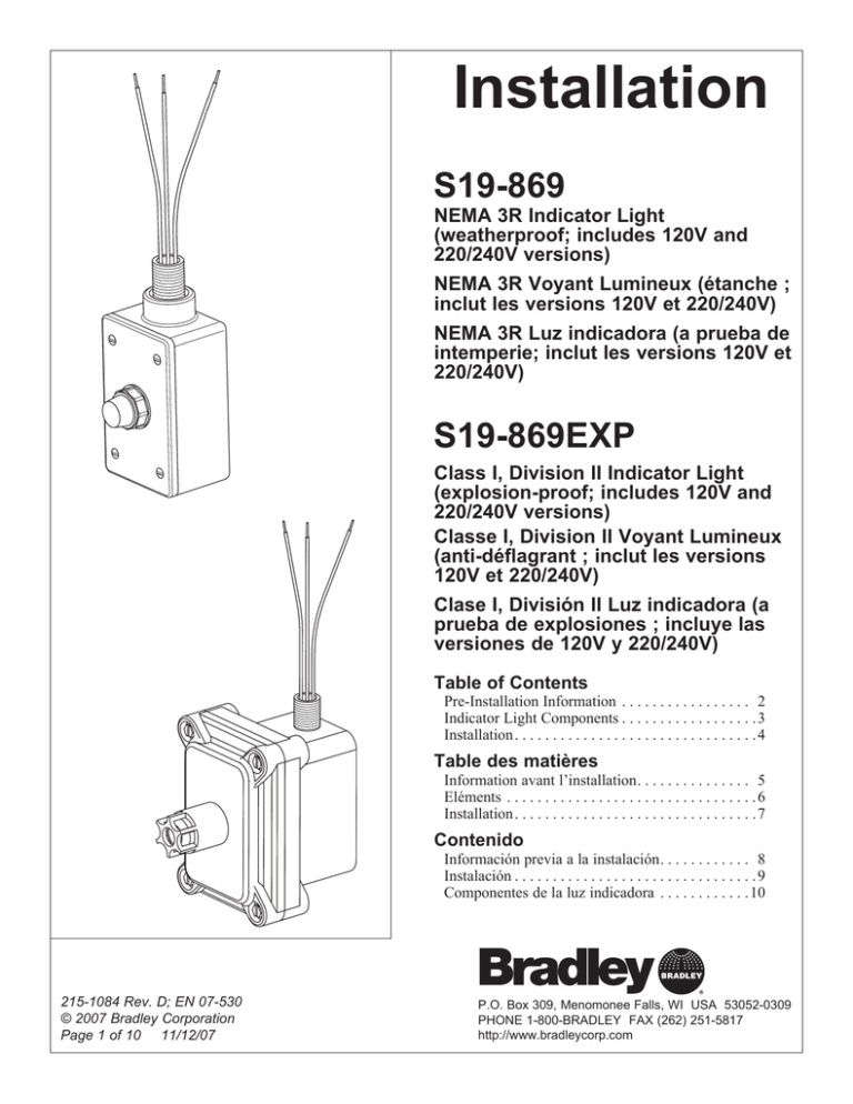
Installation S19-869 NEMA 3R Indicator Light (weatherproof; includes 120V and 220/240V versions) NEMA 3R Voyant Lumineux (étanche ; inclut les versions 120V et 220/240V) NEMA 3R Luz indicadora (a prueba de intemperie; inclut les versions 120V et 220/240V) S19-869EXP Class I, Division II Indicator Light (explosion-proof; includes 120V and 220/240V versions) Classe I, Division II Voyant Lumineux (anti-déflagrant ; inclut les versions 120V et 220/240V) Clase I, División II Luz indicadora (a prueba de explosiones ; incluye las versiones de 120V y 220/240V) Table of Contents Pre-Installation Information . . . . . . . . . . . . . . . . . 2 Indicator Light Components . . . . . . . . . . . . . . . . . . 3 Installation. . . . . . . . . . . . . . . . . . . . . . . . . . . . . . . . 4 Table des matières Information avant l’installation. . . . . . . . . . . . . . . 5 Eléments . . . . . . . . . . . . . . . . . . . . . . . . . . . . . . . . . 6 Installation. . . . . . . . . . . . . . . . . . . . . . . . . . . . . . . . 7 Contenido Información previa a la instalación. . . . . . . . . . . . 8 Instalación . . . . . . . . . . . . . . . . . . . . . . . . . . . . . . . . 9 Componentes de la luz indicadora . . . . . . . . . . . . 10 215-1084 Rev. D; EN 07-530 © 2007 Bradley Corporation Page 1 of 10 11/12/07 P.O. Box 309, Menomonee Falls, WI USA 53052-0309 PHONE 1-800-BRADLEY FAX (262) 251-5817 http://www.bradleycorp.com S19-869, S19-869EXP Installation WARNING Read this installation manual completely to ensure proper installation, then file it with the owner or maintenance department. Compliance and conformity to drain requirements and other local codes and ordinances is the responsibility of the installer. Installation Packing List IS TH SIDE UP • • • • Separate parts from packaging and make sure all parts are accounted for before discarding any packaging material. If any parts are missing, do not begin installation until you obtain the missing parts. Da Da te Da tum te Sig ned Sig ned ned P.O TES . Box DIE ESS SEST THI 309 Tes AI S , Me Rep t-op HEBGER UNI Ven ort nom DO ÄT T EAC 1ST dur til(e anyera te MA one H Tes ch ) val DAI WÖ WE e sig Un wö ma ve( RE CHE EK Fal un ne t le ters che lfun s) ls, NTL rap en fon WI chr ntli ctio eac ICH por basctio 530 ns h ift. ch t imm. nne ZU immwe Jeg im 51 S'il ek me PRÜ Tes edi and édi y à nt lich tbe FEN Sig ate ate que des e Stö trie Un ned . ly. sig me lqu val n Sig ter nt. e ves run b prü bel g cho ne sch ow sof fen rift . se cha ort , bes qui que Da me ne sem ldetäti Da te va ain n. gt Da te pas e te Sig fait et R Flush the water supply lines before beginning installation and after installation is complete. Test the unit for leaks and adequate water flow. Main water supply to the eyewash should be “ON” at all times. Provisions shall be made to prevent unauthorized shutoff. Flushing fluid should be tepid per ANSI Z358.1. P.O. BOX 309, MENOMONEE FALLS, WI 53052-0309 USA TEL: 1-800-BRADLEY FAX: (262-251-5817) http://www.bradleycorp.com 114-051 The inspection and testing results of this equipment should be recorded weekly to verify proper operation. This equipment should be inspected annually to ensure compliance with ANSI Z358.1. Workers who may come in contact with potentially hazardous materials should be trained regarding the placement and proper operation of emergency equipment per ANSI Z358.1. For questions regarding the operation or installation of this product, visit www. bradleycorp.com or call 1-800-BRADLEY. Product warranties may also be found under ”Product Information” on our web site at www.bradleycorp.com. 2 11/12/07 Bradley Corporation • 215-1084 Rev. D; EN 07-530 Installation S19-869, S19-869EXP Assembly of Components GREEN GREEN BLACK WHITE WHITE BLACK NIPPLE 269-1315 NIPPLE 269-1582 GANG BOX 269-1355 PILOT LAMP 269-1354 COVER WITH GASKET AND SCREWS 269-1357 INDICATOR LIGHT BOX 269-1310 (120V) 269-1310A (220/240V) WEATHER-PROOF INDICATOR LIGHT S19-869 EXPLOSION-PROOF INDICATOR LIGHT S19-869EXP (suitable for NEMA 4/4X locations) (rated Class I, Division 2, Groups B, C and D) Supplies required for installation: • Teflon tape or pipe sealant • Black, white and green 14 AWG wire to connect indicator light to electric power supply Bradley Corporation • 215-1084 Rev. D; EN 07-530 11/12/07 3 S19-869, S19-869EXP Installation Instructions Step 1: Mount indicator light to unit 1. Choose a location for mounting the indicator light. • The indicator light may be mounted directly to the unit junction box at one of the locations shown in Figure 1 below. Step 2: Make electrical connections 1. Connect the indicator light to the junction box following the wiring diagram (Figure 2). RECOMMENDED MOUNTING LOCATIONS FOR BOTH S19-869 AND S19-869EXP INDICATOR LIGHTS HEAT TRACE DRENCH SHOWER UNIT JUNCTION BOX RECOMMENDED MOUNTING LOCATION FOR S19-869 INDICATOR LIGHT ONLY. EXPLOSIONPROOF INDICATOR LIGHT S19-869EXP WILL NOT FIT IN THIS LOCATION. Figure 1 INDICATOR LIGHT WIRING DIAGRAM GROUND SCREW-IN JUNCTION BOX INDICATOR LIGHT GREEN WHITE BLACK POWER HEAT TRACE CABLE THERMOSTAT Figure 2 4 11/12/07 Bradley Corporation • 215-1084 Rev. D; EN 07-530 Installation S19-869, S19-869EXP AVERTISSEMENT Lire ce manuel d’installation dans son intégralité pour garantir une installation appropriée. Une fois celle-ci terminée, classer ce manuel auprès du service à la clientèle ou d’entretien. L’installateur est responsable de la conformité de l’installation aux codes pour des drain et codes et règlements en vigueur. Installation Packing List IS TH SIDE UP • • • • Assurez-vous que toutes les pièces sont incluses dans l’emballage et qu’il n’en manque aucune avant de jeter l’emballage. Ne commencez pas l’assemblage avant de recevoir les pièces manquantes. Da Da te Da tum te Sig ned Sig ned ned P.O TES . Box DIE ESS SEST THI 309 Tes AI S , Me Rep t-op HEBGER UNI Ven ort nom DO ÄT T EAC 1ST dur til(e anyera te MA one H Tes ch ) val DAI WÖ WE e sig Un wö ma ve( RE CHE EK Fal un ne t le ters che lfun s) ls, NTL rap en fon WI chr ntli ctio eac ICH por basctio 530 ns h ift. ch t imm. nne ZU immwe Jeg im 51 S'il ek me PRÜ Tes edi and édi y à nt lich tbe FEN Sig ate ate que des e Stö trie Un ned . ly. sig me lqu val n Sig ter nt. e ves run b prü bel g cho ne sch ow sof fen rift . se cha ort , bes qui que Da me ne sem ldetäti Da te va ain n. gt Da te pas e te Sig fait et R Rincez la conduite d’alimentation avant et apres l’installation. Assurez-vous que le débit d’eau est adéquat et qu’il n’y a pas de fuites. L’alimentation principale en eau doit être toujours OUVERTE. On devra prévoir des dispositions pour empêcher tout arrêt non autorisé. Le liquide de rinçage doit être tiède conformément à la norme ANSI Z358.1. P.O. BOX 309, MENOMONEE FALLS, WI 53052-0309 USA TEL: 1-800-BRADLEY FAX: (262-251-5817) http://www.bradleycorp.com 114-051 Inspectez et testez cet équipement une fois par semaine pour en assurer le bon fonctionement. Notez les dates d’inspection. Ce matériel doit être inspecté une fois par an pour assurer sa conformité à la norme ANSI Z358.1. Les ouvriers susceptibles d’entrer en contact avec des matières potentiellement dangereuses doivent recevoir une formation sur la mise en place et le bon fonctionnement du matériel d’urgence conformément à la norme ANSI Z358.1. Pour toute question concernant le fonctionnement ou l’installation de ce produit, consulter le site www.bradleycorp.com ou appeler le 1-800-BRADLEY. Les garanties de produits figurent sous la rubrique « Informations techniques » sur notre site Internet à www.bradleycorp.com. Bradley Corporation • 215-1084 Rev. D; EN 07-530 11/12/07 5 S19-869, S19-869EXP Installation Assemblage des composantes VERT VERT NOIR BLANC BLANC NOIR RÉDUCTEUR (Quantité 2, un livré sèparément) RACCORD 269-1315 RACCORD 269-1582 BOÎTIER 269-1355 TÉMOIN 269-1354 COUVERCLE AVEC JOINT ET VIS 269-1357 BOÎTIER DU VOYANT LUMINEUX LUMINEUX 269-1310 (120V) 269-1310A (220/240V) VOYANT LUMINEUX ÉTANCHE S19-869 (Convenant pour emplacements NEMA 4/4X) VOYANT LUMINEUX ANTI-DÉFLAGRANT S19-869EXP (Classe I, Division 2, Groupes B, C et D) Fournitures recommandées pour l’installation : • Ruban téflon tape ou produit d’étanchéité pour tuyaux • Fil noir, blanc, et vert calibre 14 AWG pour raccorder le voyant lumineux à l’alimentation électrique 6 11/12/07 Bradley Corporation • 215-1084 Rev. D; EN 07-530 Installation S19-869, S19-869EXP Installation Étape 1: Installer le voyant lumineux sur l’unité 1. Choisir un emplacement pour l’installation du voyant lumineux. • Le voyant lumineux peut être installé directement sur la boîte de jonction de l’unité, à l’emplacement indiqué à la Figure 1, ci-dessous. Étape 2: Raccordements électriques 1. Raccorder le témoin au boîtier de raccordement selon le diagramme (Figure 2). EMPLACEMENTS RECOMMANDÉS POUR LES VOYANT LUMINEUX S19-869 ET S19-869EXP DOUCHE D’URGENCE À ÉLÉMENT CHAUFFANT BOÎTE DE JONCTION DE L’UNITÉ EMPLACEMENT RECOMMANDÉ POUR LE VOYANT LUMINEUX S19-869 UNIQUEMENT. LE VOYANT LUMINEUX ANTI-DÉFLAGRANT S19-869EXP NE PEUT PAS ÊTRE POSÉ À CET ENDROIT. Figure 1 SCHÉMA DE CÂBLAGE DU VOYANT LUMINEUX VIS DE MASSE DANS LE BOÎTIER DE JONCTION VOYANT LUMINEUX VERT BLANC NOIR SECTEUR Figure 2 Bradley Corporation • 215-1084 Rev. D; EN 07-530 ÉLÉMENT CHAUFFANT THERMOSTAT 11/12/07 7 S19-869, S19-869EXP Installation ADVERTENCIA Lea en su totalidad este manual de instalación para garantizar una instalación adecuada. Una vez que termine la instalación, entregue este manual al propietario o al Departamento de Mantenimiento. Es responsabilidad de quien instale el equipo cumplir con los códigos para desagüe y otra códigos y ordenanzas locales. Installation Packing List IS TH SIDE UP • • • • Separar todas las piezas del material de embalaje y asegurarse que todas las piezas estén incluídas antes de desechar cualquier material de embalaje. Si faltase alguna pieza, no intentar instalar la unidad combinada Bradley hasta obtener las piezas faltantes. Da Da te Da tum te Sig ned Sig ned ned P.O TES . Box DIE ESS SEST THI 309 Tes AI S , Me Rep t-op HEBGER UNI Ven ort nom DO ÄT T EAC 1ST dur til(e anyera te MA one H Tes ch ) val DAI WÖ WE e sig Un wö ma ve( RE CHE EK Fal un ne t le ters che lfun s) ls, NTL rap en fon WI chr ntli ctio eac ICH por basctio 530 ns h ift. ch t imm. nne ZU immwe Jeg im 51 S'il ek me PRÜ Tes edi and édi y à nt lich tbe FEN Sig ate ate que des e Stö trie Un ned . ly. sig me lqu val n Sig ter nt. e ves run b prü bel g cho ne sch ow sof fen rift . se cha ort , bes qui que Da me ne sem ldetäti Da te va ain n. gt Da te pas e te Sig fait et R Aclarar el conducto del suministro de agua antes y después de la instalación. Verificar que no haya fugas y que el flujo de agua sea adecuado. El suministro principal de agua a la unidad debe estar siempre en posición “ON” (abierto). Se deben tomar medidas a fin de evitar el corte no autorizado del suministro. El líquido de limpieza debe estar tibio en conformidad con la norma ANSI Z358.1. P.O. BOX 309, MENOMONEE FALLS, WI 53052-0309 USA TEL: 1-800-BRADLEY FAX: (262-251-5817) http://www.bradleycorp.com Este equipo se debe inspeccionar, probar y anotar semanalmente para mantener un funcionamiento adecuado. Se debe revisar este equipo anualmente para asegurarse de que cumpla con la norma ANSI Z358.1. Los trabajadores que puedan tener contacto con materiales potencialmente peligrosos deben recibir capacitación sobre la ubicación y operación adecuada de los equipos de emergencia en conformidad con la norma ANSI Z358.1. 114-051 Para consultas sobre la operación o instalación de este producto, visite www. bradleycorp.com o llame al 1-800-BRADLEY. Las garantías del producto se pueden encontrar en “Información del producto” o en nuestro sitio Web, www.bradleycorp.com. 8 11/12/07 Bradley Corporation • 215-1084 Rev. D; EN 07-530 Installation S19-869, S19-869EXP Armado de los componentes VERDE VERDE NEGRO BLANCO BLANCO NEGRO TUBO CORTO DE EMPALME 269-1315 REDUCTOR DE CONDUCTO (2, uno enviado suelto) TUBO CORTO DE EMPALME 269-1582 CAJA MÚLTIPLE 269-1355 LUZ PILOTO 269-1354 CAJA DE LA LUZ INDICADORA 269-1310 (120V) 269-1310A (220/240V) CUBIERTA CON JUNTA Y TORNILLOS 269-1357 LUZ INDICADORA A PRUEBA DE INTEMPERIE S19-869 LUZ INDICADORA A PRUEBA DE EXPLOSIONES S19-869EXP (apropiado para ubicaciones NEMA 4/4X) (clasificación de Clase I, División 2, Grupos B, C y D) Materiales que se requieren para la instalación: • Cinta de teflón o composición obturadora de tubos • Cable de 14 AWG negro, blanco y verde para conectar la luz indicadora al suministro de energía eléctrica Bradley Corporation • 215-1084 Rev. D; EN 07-530 11/12/07 9 S19-869, S19-869EXP Installation Instalación Paso 1: Montar la luz indicadora en la unidad 1. Elegir una ubicación para el montaje de la luz indicadora. • La luz indicadora puede montarse directamente en la caja de conexiones de la unidad en cualquiera de las ubicaciones que se muestran en la figura 1 más abajo. Paso 2: Realizar las conexiones eléctricas 1. Conectar la luz indicadora a la caja de conexiones siguiendo el diagrama de cableado (figura 2) que se ofrece. PUNTOS DE MONTAJE RECOMENDADOS PARA LAS LUCES INDICADORAS S19-869 Y S19-869EXP DUCHA DE ASPERSIÓN CON CONTROL TÉRMICO CAJA DE LA UNIDAD DE CONEXIONES UBICACIÓN DE MONTAJE RECOMENDADA PARA LA LUZ INDICADORA S19-869 SOLAMENTE. LA LUZ INDICADORA A PRUEBA DE EXPLOSIONES S19-869EXP NO ENCAJARÁ EN ESTA UBICACIÓN. Figura 1 DIAGRAMA DE CABLEADO DE LA LUZ INDICADORA CAJA DE CONEXIONES LUZ INDICADORA VERDE BLANCO NEGRO ENERGÍA ELÉCTRICA TERMOSTATO Figura 2 10 CABLE DE CONTROL TÉRMICO 11/12/07 Bradley Corporation • 215-1084 Rev. D; EN 07-530
