a magnetic flux is created which will attract the armature
Anuncio
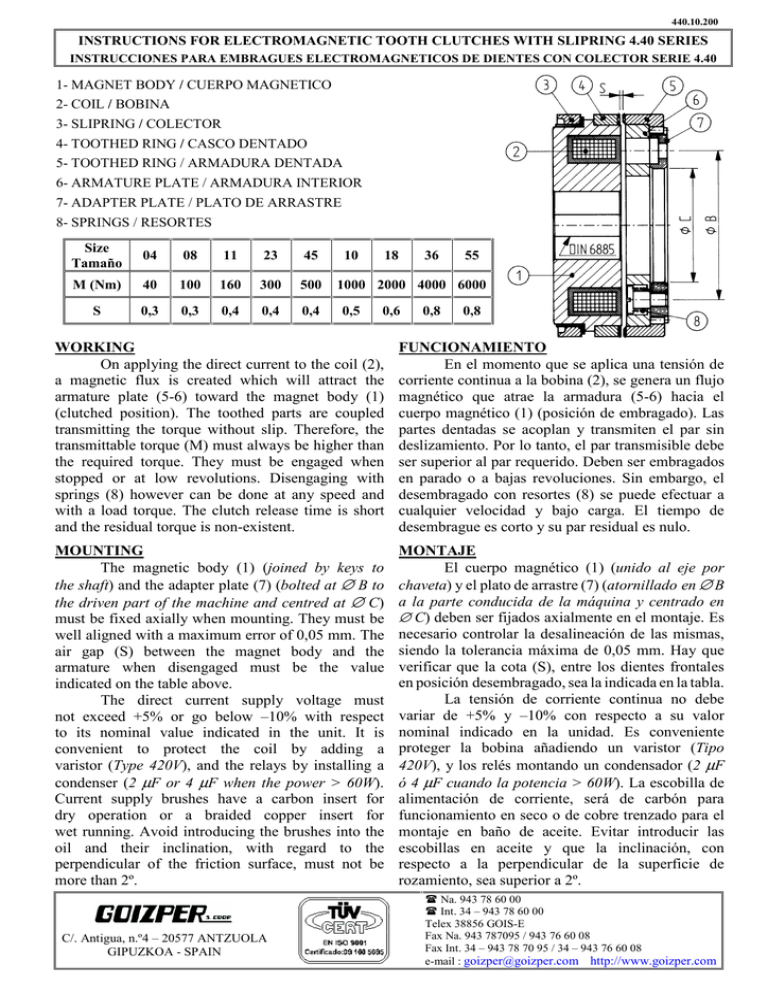
440.10.200 INSTRUCTIONS FOR ELECTROMAGNETIC TOOTH CLUTCHES WITH SLIPRING 4.40 SERIES INSTRUCCIONES PARA EMBRAGUES ELECTROMAGNETICOS DE DIENTES CON COLECTOR SERIE 4.40 1- MAGNET BODY / CUERPO MAGNETICO 2- COIL / BOBINA 3- SLIPRING / COLECTOR 4- TOOTHED RING / CASCO DENTADO 5- TOOTHED RING / ARMADURA DENTADA 6- ARMATURE PLATE / ARMADURA INTERIOR 7- ADAPTER PLATE / PLATO DE ARRASTRE 8- SPRINGS / RESORTES Size Tamaño 04 08 11 23 45 M (Nm) 40 100 160 300 500 S 0,3 0,3 0,4 0,4 0,4 10 18 36 55 1000 2000 4000 6000 0,5 0,6 0,8 0,8 WORKING On applying the direct current to the coil (2), a magnetic flux is created which will attract the armature plate (5-6) toward the magnet body (1) (clutched position). The toothed parts are coupled transmitting the torque without slip. Therefore, the transmittable torque (M) must always be higher than the required torque. They must be engaged when stopped or at low revolutions. Disengaging with springs (8) however can be done at any speed and with a load torque. The clutch release time is short and the residual torque is non-existent. FUNCIONAMIENTO En el momento que se aplica una tensión de corriente continua a la bobina (2), se genera un flujo magnético que atrae la armadura (5-6) hacia el cuerpo magnético (1) (posición de embragado). Las partes dentadas se acoplan y transmiten el par sin deslizamiento. Por lo tanto, el par transmisible debe ser superior al par requerido. Deben ser embragados en parado o a bajas revoluciones. Sin embargo, el desembragado con resortes (8) se puede efectuar a cualquier velocidad y bajo carga. El tiempo de desembrague es corto y su par residual es nulo. MOUNTING The magnetic body (1) (joined by keys to the shaft) and the adapter plate (7) (bolted at ∅ B to the driven part of the machine and centred at ∅ C) must be fixed axially when mounting. They must be well aligned with a maximum error of 0,05 mm. The air gap (S) between the magnet body and the armature when disengaged must be the value indicated on the table above. The direct current supply voltage must not exceed +5% or go below –10% with respect to its nominal value indicated in the unit. It is convenient to protect the coil by adding a varistor (Type 420V), and the relays by installing a condenser (2 µF or 4 µF when the power > 60W). Current supply brushes have a carbon insert for dry operation or a braided copper insert for wet running. Avoid introducing the brushes into the oil and their inclination, with regard to the perpendicular of the friction surface, must not be more than 2º. MONTAJE El cuerpo magnético (1) (unido al eje por chaveta) y el plato de arrastre (7) (atornillado en ∅ B a la parte conducida de la máquina y centrado en ∅ C) deben ser fijados axialmente en el montaje. Es necesario controlar la desalineación de las mismas, siendo la tolerancia máxima de 0,05 mm. Hay que verificar que la cota (S), entre los dientes frontales en posición desembragado, sea la indicada en la tabla. La tensión de corriente continua no debe variar de +5% y –10% con respecto a su valor nominal indicado en la unidad. Es conveniente proteger la bobina añadiendo un varistor (Tipo 420V), y los relés montando un condensador (2 µF ó 4 µF cuando la potencia > 60W). La escobilla de alimentación de corriente, será de carbón para funcionamiento en seco o de cobre trenzado para el montaje en baño de aceite. Evitar introducir las escobillas en aceite y que la inclinación, con respecto a la perpendicular de la superficie de rozamiento, sea superior a 2º. C/. Antigua, n.º4 – 20577 ANTZUOLA GIPUZKOA - SPAIN Na. 943 78 60 00 Int. 34 – 943 78 60 00 Telex 38856 GOIS-E Fax Na. 943 787095 / 943 76 60 08 Fax Int. 34 – 943 78 70 95 / 34 – 943 76 60 08 e-mail : [email protected] http://www.goizper.com
