parentesi - Flos.com
Anuncio
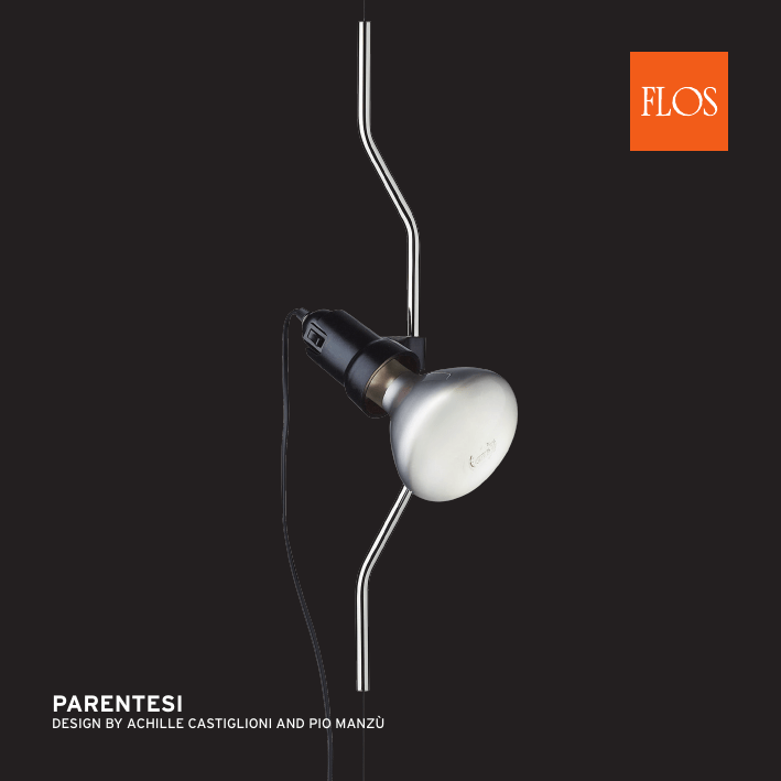
PARENTESI DESIGN BY ACHILLE CASTIGLIONI AND PIO MANZÙ <IT> ISTRUZIONI DI INSTALLAZIONE ED IMPIEGO <GB> INSTRUCTION FOR CORRECT INSTALLATION AND USE <DE> INSTALLATION - UND GEBRAUCHSANWEISUNGEN <FR> INSTRUCTIONS D’INSTALLATION ET D’UTILISATION ATTENZIONE! La sicurezza dell’apparecchio é garantita solo rispettando queste istruzioni sia in fase di installazione che di impiego; é pertanto necessario conservarle. WARNING! The safety of this fitting can only be guaranteed if these instructions are observed, during both installation and use. Please retain these instructions safety. ATTENTION! La sécurité de cet appareil n’est garantie que si ces instructions sont respectées durant l’installation et lors de l’utilisation; il convient donc les conserver. AVVERTENZE: - All’atto dell’installazione ed ogni volta che si interviene sull’apparecchio, assicurarsi che sia stata tolta la tensione di alimentazione. - L’apparecchio non può essere in alcun modo modificato o manomesso, ogni modifica ne può compromettere la sicurezza rendendo lo stesso pericoloso. FLOS declina ogni responsabilità per i prodotti modificati. - Se il cavo flessibile si danneggia, deve essere sostituito da FLOS o da personale qualificato al fine di evitare pericoli. riportato sull’apparecchio indica che il - Il simbolo prodotto deve essere smaltito in modo differenziato dai rifiuti urbani. riportato sull’apparecchio indica Il simbolo la distanza minima alla quale va posto il soggetto da .illuminare ATTENZIONE! Il sollevamento del contrappeso (A - fig.7) provoca la perdita di tensione meccanica del cavo di .sostegno con conseguente caduta del supporto lampada REMARKS: - When installing and whenever acting on the appliance, ensure that the power supply has been switched off. - The appliance may in no way be modified or tampered with, any modification may compromise safety causing the appliance to become dangerous. FLOS declines all responsibility for products that are modified. - Should the external trailing cable get damaged,it must be replaced by FLOS or by qualified personnel in order to avoid any danger. shown on the device indicates that the - The symbol product must be thrown out in a different manner than with the urban trashes. marked on the appliance - The symbol indicates the minimum distance at which the subject to be illuminated should be placed. - WARNING: Raising the counterweight (A - Fig.7) will cause loss of mechanical tension in the suspension wire and the lamp support will fall. ACHTUNG! Wir garantieren nur dann für die Sicherheit der Leuchte, wenn diese Anweisungen sowohl bei der Installation als auch beim Gebrauch genau beachtet werden. Es ist daher ratsam, sie aufzubewahren. DATI TECNICI Lampada ad incandescenza MAX 150W attacco E27 tipo IRR D125. ISTRUZIONI PER LA PULIZIA DELL’APPARECCHIO Per la pulizia dell’apparecchio utilizzare esclusivamente un panno morbido eventualmente inumidito con acqua e sapone. - Attenzione: non utilizzare alcool o solventi. TECHNICAL DATA Incandescent light bulb MAX 150W, E27 fitting, IRR D125 type. CLEANING INSTRUCTIONS Use only a soft cloth to clean the appliance, dampened with water and soap or mild cleanser if needed for resistant dirt. - Warning: do not use alcohol or other solvents. BEMERKUNGEN: - Bei der Installation und bei Eingriffen an der Leuchte ist sicherzustellen, daß die Anlage vom Netz abgeschaltet ist. - Der Apparat darf auf keinen Fall veraendert oder unerlaubt geoeffnet werden, jede Veraenderung desselben kann die Sicherheit in Frage stellen und somit gefaehrlich werden. FLOS lehnt jede Verantwortung fuer unsachgemaess behandelte Produkte ab. - Falls das flexible äußere Kabel beschädigt wird, muß es von FLOS oder von qualifiziertem Personal ersetzt werden, um Gefahren zu vermeiden. zeigt - Das auf dem Gerät wiedergegebene Symbol an, dass das Produkt getrennt vom Stadtmüll entsorgt werden muss. auf der Leuchte gibt den - Das Symbol erforderlichen Mindestabstand zum beleuchteten Gegenstand an. -ACHTUNG: Das Anheben des Gegengewichts (A - fig.7) verursacht einen mechanischen Spannungsverlust des St¸tzkabels mit dem nachfolgenden Fall des Lampenhalters. TECHNISCHE DATEN Glühlampe MAX 150W Anschluss E27 typ IRR D125. REINIGUNGSVORSCHRIFTEN Bei der Reinigung der Leuchte darf man ausschließlich weiche Tücher verwenden. Eventuell kann man diese mit Wasser und Seife oder mit einem neutralen Reinigungsmittel anfeuchten. - Achtung: Weder Alkohol noch Lösungsmittel verwenden. NOTICES: - Au moment de l’installation et chaque fois que l’on intervient sur l’appareil, s’assurer que la tension d’alimentation a été coupée. - L’appareil ne peut être modifié ou altéré de quelque manière que ce soit, toute modification pouvant compromettre sa sécurité et le rendre dangereux. FLOS décline toute responsabilité sur les produits modifiés. - Si le câble flexible est endommagé, il doit être remplacé par FLOS ou par une personne qualifiée afin d’éviter tout danger. - Le symbole montré sur l’appareil indique que le produit doit être éliminé d’une autre façon que celle avec les déchets urbains. présent sur l’appareil indique - Le symbole la distance minimale à lequelle doit être placé le sujet à éclairer. -ATTENTION: soulever le contrepoids (A - Fig.7) annule la tension mécanique du câble et entraîne la chute du support de lampe. DONNEES TECHNIQUES Ampoule incandescente MAX 150W culot E27 type IRR D125. INSTRUCTIONS POUR LE NETTOYAGE Pour le nettoyage de l’appareil utiliser exclusivement un chiffon doux, humecté si nécessaire, avec de l’eau et du savon ou avec un détergent neutre pour les salissures les plus tenaces. - Attention: ne pas utiliser d’alcool ou solvents. <ES> INSTRUCCIONES DE INSTALACIÓN Y DE USO <PT> INSTRUÇÕES INSTALAÇÃO E USO <RUS> ИНСТРУКЦИИ ПО МОНТАЖУ И ПРИМЕНЕНИЮ ¡ATENCIÓN! La seguridad del aparato sólo puede garantizarse con la condición de que se respeten las siguientes instrucciones, tanto en la fase de instalación como de uso, por lo cual se recomienda conservarlas. ATENÇÃO! A segurança do aparelho é garantida somente se respeitarmos as instruções tanto na fase de instalação como na de uso; portanto é necessário conservar tais instruções. ВНИМАНИЕ! ADVERTENCIA: - Para efectuar la instalación, y toda vez que se efectúe alguna operación en el aparato, asegurarse de haber cortado la corriente eléctrica. - El aparato no puede ser en ningùn caso modificado o forzado, cualquier modificaciòn puede comprometer la seguridad haciéndolo peligroso. FLOS declina cualquier responsabilidad por los productos modificados. - Si le cordón flexible externo se deteriora , tiene que ser remplazado por personal de Flos, o en ausencia, por personal cualificado, con el fin de evitar cualquier daño personal. que aparece en el aparato indica que el - El símbolo producto debe ser eliminado en modo diferenciado del resto de los desechos urbanos. marcado en el aparato indica la - El símbolo distancia mínima a la que se debe colocar el objeto que se tiene que iluminar. - ATENCIÓN: La elevación del contrapeso (A - fig.7) provoca la pérdida de la tensión mecánica del cable de sujeción con la consiguiente caída del soporte de la lámpara. ADVERTÊNCIA: - Para efectuar la instalación, y toda vez que se efectúe alguna operación en el aparato, asegurarse de haber cortado la corriente eléctrica. - De forma alguma o aparelho deve ser modificado ou alterado, toda e qualquer modificação pode comprometer a segurança tornando o aparelho perigoso. FLOS declina toda e qualquer responsabilidade pelos produtos modificados. - Se o cabo flexível está danificado, deve ser substituído pela FLOS ou por pessoal qualificado para evitar qualquer perigo. - O símbolo indicado no aparelho indica que o produto deve ser eliminado de forma diferenciada em relação ao lixo urbano. colocado no aparelho indica a - O símbolo distância mínima onde se colocar o objeto a ser iluminado. - ATENÇÃO! O levantamento do contra-peso (A - fig.7) provoca a perda da tensão mecânica do cabo de sustentação com a consequente queda do suporte da lâmpada. DATOS TÉCNICOS Bombilla de incandescencia MAX 150W conexión E27 tipo IRR D125. INSTRUCCIONES PARA LIMPIAR EL APARATO Para la limpieza del aparato, utilizar exclusivamente un paño suave. En caso de suciedad más resistente, humedecer el paño con agua y jabón o un detergente neutro. - Advertencia: no emplear alcohol ni disolventes. Надёжность устройства гарантируется только при соблюдении данных инструкций, как в фазе монтажа, так и при применении, поэтому необходимо обеспечить их сохранность. ПРЕДУПРЕЖДЕНИЯ: -В момент установки и каждый раз при проведении работ с устройством, убедиться в снятии напряжения питания. -Устройство не может изменяться или разбираться, любые изменения могут нарушить надёжность, делая его опасным. FLOS не несёт ответственность за измененную продукцию. -При повреждении гибкого кабеля он должен быть заменён FLOS или квалифицированным персоналом в целях предотвращения опасности. -Символ приведённый на устройстве, указывает на то, что данная продукция должна быть переработана отдельно от городских отходов. - Обозначение приведенное на устройстве, указывает минимальное расстояние, на котором должен располагаться освещаемый объект. -ВНИМАНИЕ! Подъём противовеса (A - рис.7) приводит к потере механического натяжения опорного кабеля с последующим падением опоры лампы. DADOS TÉCNICOS Lâmpada incandescente MAX 150W ligação E27 tipo IRR D125. ТЕХНИЧЕСКИЕ ДАННЫЕ INSTRUÇÕES PARA A LIMPEZA DO APARELHO Para limpeza do aparelho utilizar exclusivamente um tecido macio eventualmente úmido com água e sabão ou detergente neutro para a sujeira mais difícil. - Atenção: não utilizar álcool ou solventes. ИНСТРУКЦИИ ПО ОЧИСТКЕ УСТРОЙСТВА Лампа накаливания МАКС. 150Вт цоколь E27 тип IRR D125. Для очистки устройства использовать только мягкую тряпку, смоченную водой с мылом или нейтральным моющим средством для наиболее стойких загрязнений. - Внимание: Не использовать спирт или другие растворители. Fig.1 Fig.2 <IT> Fig.1 Svitare il gancio dal tassello ad espansione farlo passare attraverso il rosone; praticare un foro nel soffitto e inserire il tassello ad espansione. Avvitare con forza e fissare il rosone. NOTA: scegliere il tassello ad espansione idoneo per la superficie destinata al montaggio. Fig.2 Agganciare all’anello aperto il capo della fune di acciaio. <GB> Fig.1 Unscrew hook from expansion bolt, pass hook through ceiling rose ; drill a hole in the ceiling and insert the expansion bolt with open hook. Screw up tight and fix ceiling rose. NOTE: Select and employ screw anchor which is suited to the surface where the appliance is to be installed. Fig.2 Slip the end of the steel cable on to the open hook. <DE> Abb.1Haken vom Spreizdübel schrauben und durch das Radfenster führen; In die Decke ein Loch bohren und den Expansionsdübel einführen. Schraube kräftig anziehen und die Rosette befestigen. HINWEIS: für die Montage vorgesehene Fläche passende Spreizdübel auswählen. Abb.2 Am offenen Ring das Drahtseilend einhängen. <FR> Fig.1 Dévisser le crochet de la cheville à expansion et le faire passer à travers la rosace; faire un trou dans le plafond, et insérer la cheville à expansion. Visser à fond, et fixer la rosace. NOTE : choisir une cheville à expansion adaptée à la surface de montage. Fig.2 Accrocher l’extrémité du câble en acier à l’anneau ouvert. <ES> Fig.1 Desenroscar el gancho del taco a expansión y pasarlo a través del rosetón; Realizar un agujero en el techo e introducir el taco a expansión. Atornillar con fuerza y fijar el rosetón. NOTA IMPORTANTE: Elegir el taco de expansión idoneo para la superficie destinada al montaje. Fig.2 Enganchar el extremo del cable de acero en el anillo abierto. <PT> Fig.1 Soltar o gancho da bucha de expansão e passar trave da copinha; fazer um furo no tecto e inserir a bucha de expansão. Aparafusar com força e fixar a copinha. OBSERVAR BEM: Escolher a bucha de expansão correcta para a superfície de montagem. Fig.2 Enganchar ao anel aberto a ponta do cabo de aço. <RUS> Рис.1 Отвинтить крючок от расширительной вставки, провести его через розетку; сделать отверстие на потолке и вставить расширительную вставку. Тщательно завинтить и закрепить розетку. ПРИМЕЧАНИЕ: выбрать расширительную вставку, пригодную для поверхности, предназначенной для монтажа. Рис.2 Прикрепить к открытому кольцу конец стального троса. Fig.3 Fig.4 <IT> cm. 19 (cm 18)* <GB> <DE> <FR> Fig.5 Fig.6 <ES> <PT> <RUS> Fig.3Tagliare la fune a circa cm. 19 (* con elemento complementare: cm 18) dal pavimento. Fig.4 Infilare il supporto di gomma sul tubo sagomato, bagnandone la superficie per favorirne lo scorrimento. Fig.5 Inserire e far scorrere la fune nel tubo sagomato che potrà essere momentaneamente bloccato alla stessa con del nastro adesivo. Fig.6 Inserire il capo della fune nel foro posto all’estremità del tenditore e serrare la vite-morsetto. Agganciare il tenditore al contrappeso (A). Fig.3Cut the cable to the approriate lenght reaching approximately 7,5 inches (* with extra piece: 7 inches) from the floor allowing for the weight and adjustable bolt. Fig.4 Slide the hard rubber lampholder support on to the shaped tube. Fig.5 Insert and slide the steel cable through the shaped tube which can be temporarily fixed to the steel cable by an adhesive tape. Fig.6 Put the end of the steel cable into the upper hole of the adjustable bolt, tighten the securing screw and hook the adjustable bolt to the counterweight (A). Abb.3 Das Drahtseil etwa 19 cm (*mitZusatzelement: cm18) vom Boden entfernt abschneiden. Abb.4 Das Gummilager in das schablonisierte Rohr einführen, wobei seine Oberfläche genässt weden soll, um das Gleiten zu erleichtern. Abb.5 Das Seil in das schablonisierte Rohr einfürhen und nachziehen Das Rohr mit Klebestreifen eventuell befestigen. Abb.6 Das Seilende in das obere Loch der Spannvorrichtung einfürhen die Klemmschraube anziehen und die Spannvorrichtung an das Gegengewicht (A) anhaken. Fig.3Couper le fil à environ 19 cm du sol (*avec élément complémentaire: à 18 cm du sol). Fig.4 Enfiler le support en caoutchouc sur le tube, en l’humectant pour en faciliter le glissement. Fig.5 Insérer et faire coulisser le câble en acier dans le tube, puis le bloquer momentanément avec du ruban adhésif. Fig.6 Insérer l’extrémité du fil en acier dans l’orifice placé à l’extrémité du tendeur puis visser l’écrou de serrage. Accrocher le tendeur au contrepoids (A). Fig.3Cortar el cable a unos 19 cm (*con elemento complementario: cm 18) del suelo. Fig.4 Pasar el soporte de goma sobre el tubo perfilado, humedeciendo la superficie para favorecer el deslizamiento. Fig.5 Introducir y deslizar el cable en el tubo perfilado que podrá ser momentáneamente fijado al mismo con cinta adhesiva. Fig.6 Pasar el extremo del cable por el agujero de la extremidad del tensor y apretar el tornillo-borne. Enganchar el tensor al contrapeso. (A) Fig.3Cortar o cabo a aproximadamente 19 cm (*com elemento complementar a: cm 18) do chão. Fig.4 Enfiar o suporte de borracha no tubo moldado, molhando a superfície para favorecer o escorrimento. Fig.5 Inserir e fazer escorrer o cabo no tubo moldado que poderá estar momentaneamente bloqueado com fita adesiva. Fig.6 Inserir a ponta do cabo no furo da extremidade do tensor e apertar o parafuso-borne. Enganchar o tensor ao contra-peso (A). Рис.3 Обрезать трос на расстоянии приблизительно 19 см (* с дополнительным элементом: 18 см) от пола. Рис.4 Надеть резиновую опору на профилированную трубу, смачивая поверхность в целях улучшения скольжения. Рис.5 Вставить и обеспечить скольжение троса в профилированной трубе, которая может быть временно прикреплена к нему посредством клейкой ленты. Рис.6 Вставить конец троса в отверстие, расположенное на конце натяжного устройства, и затянуть винт-зажим. Зацепить натяжное устройство к противовесу (A). Fig.7 Fig.8 A <IT> Fig.7 Regolato il tenditore in modo che il contrappeso sfiori il pavimento, stringerne i dadi di bloccaggio. Controllare la perpendicolarità della fune. Fig.8 Infilare nel supporto in gomma il portalampade fino al limite delle alette di areazione. Fig.7 Regulate the tension of the cable by turning the bolt so that the counterweight just touches the floor. Tighten the fixing nuts and check that the cable is plumb. Fig.8 Pass through the hard rubber support the lampholder push it to the limit of the cooling fins. <DE> Abb.7 Nachdem die Spannvorrichtung so eingestellt ist, dass das Gegengewicht den Boden berührt, sind seine Befestigungsmuttern anzuziehen. Das lotrechte Fallen des Seils ist nachzuprüfen. Abb.8 Die Fassung in das Gummilager bis zur Begrenzung der Ventilationsflügel einführen. <FR> Fig.7 Après avoir réglé le tendeur de manière à placer le contrepoids à ras du plancher, visser les boulons de blocage. Contrôler que le fil est perpendiculaire. Fig.8 Introduire la douille dans le support en caoutchouc jusqu’à la limite des ailettes d’aération Fig.7 Una vez regulado el tensor en modo que el contrapeso roce el suelo, apretar las tuercas de bloqueo. Controlar la perpendicularidad del cable. Fig.8 Introducir en el soporte de goma el casquillo portalámpara hasta el límite de las aletas de aireación. <PT> Fig.7 Regulado o tensor de forma que o contra-peso toque o pavimento, apertar as porcas de bloqueio. Controlar a perpendicularidade do cabo. Fig.8 Enfiar no suporte de borracha o porta-lâmpadas até o limite das aletas de aeração. <RUS> Рис.7 После регулировки натяжного устройства таким образом, чтобы противовес касался пола, затянуть блокировочные гайки. Проверить перпендикулярность троса. Рис.8 Вставить в резиновую опору держатель лампы до предела воздушных лопаток. <IT> INSTALLAZIONE ELEMENTO COMPLEMENTARE - Per l’installazione dell’elemento complementare fare riferimento alle figure 4, 5 e 6; <GB> INSTALLATION OF EXTRA PIECE – To install the extra piece refer to figures 4, 5 and 6; <DE> INSTALLATION ZUSATZELEMENT – Nehmen Sie für Die installation des Zusatselements bitte auf Die Abbildungen 4, 5 und 6 bezug; <FR> INSTALLATION DE L’ELEMENT COMPLEMENTAIRE - Pour installer un élément complémentaire, se reporter aux figures 4, 5 et 6. <ES> INSTALACION DEL ELEMENTO COMPLEMENTARIO – Para instalar el elemento complementario tomar como referencia las figuras 4, 5 y 6; <PT> INSTALAÇÃO DO ELEMENTO COMPLEMENTAR – Para a instalação do elemento complementar usar como referências as figuras 4, 5 e 6; <RUS> МОНТАЖ ДОПОЛНИТЕЛЬНОГО ЭЛЕМЕНТА – Для монтажа дополнительного элемента см.рис. 4, 5 и 6; 18345 - 18/01/2016 <GB> <ES> www.flos.com
