El CD-Audio
Anuncio
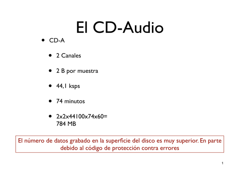
• CD-A • • • • • El CD-Audio 2 Canales 2 B por muestra 44,1 ksps 74 minutos 2x2x44100x74x60= 784 MB El número de datos grabado en la superficie del disco es muy superior. En parte debido al código de protección contra errores 1 HA(2+8(ABA(A"'+&#&"+ Superficie de datos HA ABA N&35$"(OP( Paso de pista Long. de resalte mínima (1 capa) (nm) Long. de resalte mínima (2 capas) (nm) ( ( CD 1600 830 - DVD 740 400 440 ( 2 Estructura DVD-A • • Densidad DVD = (1600/740)(830/400) = 4,5 Densidad CD-A Capacidad DVD = 4700/780 = 6 Capacidad CD-A 1 cara, 1 capa (4,7 GB) 1 cara, 2 capas (8,5 GB) 2 cara, 2 capas (17 GB) • El código de protección es menos redundante 3 Contenido DVD-A Tipo de disco / Contenido Tipo de reproductor DVD- Audio sin vídeo DVD- Audio sin vídeo DVD-Audio sólo audio • • Audio DVD-Audio universal • • • Audio DVD-Vídeo • No reproducible Video • • Texto informativo No reproducible Elementos de audio para DVD-Audio y DVD- Texto informativo Imágenes fijas DVD- Video Menús visuales Audio, texto, gráficos y • Todo el vídeo • Todo el vídeo video • Sólo vídeo 4 Opciones en DVDAudio 16, 20 ó 24 bits 44.1 48 88.2 96 176.4 192 Mono (1.0) Sí Sí Sí Sí Sí Sí Estéreo (2.0) Sí Sí Sí Sí Sí Sí Cuadrafónico (4.0) Envolvente (5.1) Sí Sí Sí Sí No No Sí Sí Sí Sí No No 5 Duraciones en DVD-A Resolución F. muestreo (kHz) Canales Flujo binario (Mbps) Duración (minutos) 16 44.1 2 1.41 422 16 48 2 1.54 388 20 96 4 7.68 78 24 192 4 9.22 65 • Disco de 1 capa, 1 cara • Sin compresión MLP • Con compresión MLP (45% de reducción), la capacidad aumenta un 80 % 6 CD-A vs SACD CD-A SACD Diámetro 120 mm 120 mm Grosor 1,2 mm 1,2 mm Caras Una Una Capas Una Dos: CD y HD 780 MB - 780 MB 4.700 MB 16 bit PCM 44,1 ksps 16 bit PCM 44,1 ksps Código Super Audio - DSD 1 bit 2,8224 Msps Multicanal - 6 canales 5-20.000 Hz 0-100.000 Hz (DSD) 96 dB 120 dB Duración de grabación 74 minutos 74 minutos Extras Texto CD Texto, gráficos, vídeo Capacidad de datos CD HD Código Audio Estándar Respuesta en frecuencia Margen dinámico 7 • Capacidad CD-A • • • • • 2 Canales 2 B por muestra • SACD • • 6 Canales • • 74 minutos 44,1 ksps 74 minutos 2x2x44100x74x60= 784 MB 2,8224 Mb/s/canal (64 b/muestra a 44,1ksps) 6x2822400x74x60= ¡9.400 MB! El SACD incluye un método de compresión sin pérdidas (DST: direct stream transfer) que reduce el número de datos al 50%. La capacidad necesaria es, por tanto de 4.700 MB 8 DSD en el SACD Difference between PCM & DSD PCM Standard multibit PCM recording requires a decimation filter on the recording side and an oversampling filter on the playback side . DSD Direct Stream Digital eliminates the need for these filters, enabling sound to be recorded directly in the 1-bit signal format. 9 “ventaja” del SACD 10kHz square wave input 10kHz square wave input 44.1kHz/16-bit output Direct Stream Digital output The above diagram demonstrates the high fidelity of DSD recording. The 10kHz square wave frequency (top line in the diagram) includes high-frequency components which clearly exceed the audio range. With the 16-bit PCM system, these are converted into 10kHz sine waves (left diagram). However, with the 1-bit DSD system, the reproduced sound wave is nearly identical to the original sound wave (right diagram). Una onda cuadrada y una sinusoide de 10 kHz suenan igual para el oído humano Son las no-linealidades de los amplificadores las que producen la diferencia. 10 Estructura SACD Hybrid Disc Construction Hybrid Disc Signal Heading 11 SACD Disc Types Single Layer Disc Formatos SACD Dual Layer Disc Hybrid Layer Disc 12 El SACD híbrido Hybrid Disc Content 12 cm CD LAYER PCM Stereo HIGH DENSITY LAYER Enrichment: • Lyrics • Graphics • Video DSD Multi-Channel DSD Stereo 13 Reproductor SACD To find out how much more there is to hear, visit a Sony SACD retailer. Call 1-800-222-SONY or visit www.sony.com Sony Electronics Inc. 1 Sony Drive, Park Ridge NJ 07656 http://www.sony.com © 1999 Sony Electronics Inc. All rights reserved. Reproduction in whole or in part without written permission is prohibited. Sony, DSD, Direct Stream Digital, Dual Discrete, Super Audio CD, the DSD logo and the Super Audio CD logo are trademarks of Sony. Direct Stream Transfer is a trademark of Philips. 14 onstruction. neral Impedance r positions the active + - - Level [d signal path, we chose design goals: flat amplitude response, maximum -50 -100 high-frequency extension, low noise, optimum Voltage for the analog stage is provided by a 20 + 100 1k Frequency [Hz] 10k 100k discrete left and right power supply secondaries, Sony's filter design achieves phase characteristics and suitability with located directly on the audio circuit board. Electrónica flat response to 50,000 Hz. rcuit Board Layout. Separate left and right 3-layer bus bars help ng such meticulous attention to the minimize power supply impedance. To optimize op amps and other active circuit elements outare of the signal path. grounding, the audio output terminals con- The GIC filter is followed by a discrete nected to the audio circuit board using a thick component buffer amp, for optimum coupling e signal path, to on, design and execution of each ony was equally careful in the physical e original sound. ent of circuits in the chassis. circuit board—which includes the DSP , RF processing LSI and system control The GIC low-pass filter takes transistors, downstream audio equipment. to a preamplifier. The GIC circuit of the Sony SCD-1 and copper plate. SCD-777ES take all these factors into account. oned directly underneath the fixed lter Frequency response is flat to 50,000 Hz (some r example, it required a hole in the cir- two and a half times the response of a CD player). ve assembly. This was a design chal- d to accommodate a support post. But guration reduces signal runs from the ups, reducing exposure to possible ce. + circuit board itself follows Sony's nimum" design, with key components ass through concentrated as possible. To accomelements goal, Sony designed the printed circuit Above 50,000 Hz, response begins to roll off slowly. The result is smooth, open, non-fatiguing sound with exceptional definition and dynamics. SCD-1 Internal structure 4 layers. And then applied surface-mount Fig. 12 Characteristics of Low-Pass Filter Used in SCD-1 small-scale on both sides of the Signals dochips not pass through anya active elements a result, phenomenal amount of ating the main + circuit board and placing he mechanism leaves ample space in - circuits that need is for the two g out." The power supply and the audio ard. 0 10 Level [dB] ts comfortably on a single, small board. Analog circuit with GIC low-pass filter. -50 -100 20 100 SCD-1 Main circuit board (top) 1k Frequency [Hz] 10k 100k audio circuit board includes so many nts that determine sound quality, Sony attention to its layout and construc- is a double-sided glass epoxy board s bar and symmetrical left/right layout. Sony's filter design achieves flat response to 50,000 Hz. l LSIs, including VC24, S-TACT and takes transistors, ve circuit elements mponents. And they're all concentrated ulse D/A Converter, are all surface- 15
