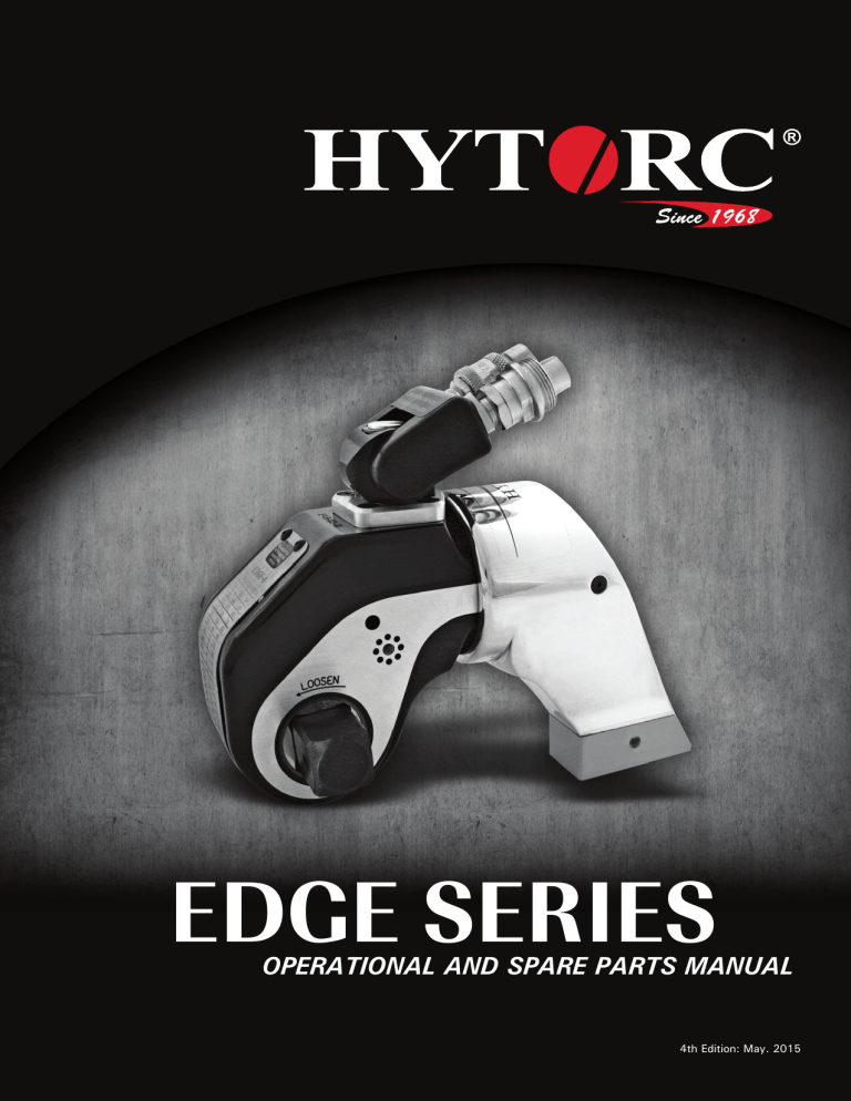
EDGE SERIES OPERATIONAL AND SPARE PARTS MANUAL 4th Edition: May. 2015 This manual applies to all tool part numbers in the EDGE Product Families. The complete part number matrix which applies to this manual can be found in Appendix A and B respectively. It is recommended the manual is kept up-to-date by checking the edition and date code at the bottom of this page by utilizing the HYTORC website and downloading a copy of the most recent edition as needed. EDGE PRODUCT FAMILY: EDGE-.5, EDGE-2, EDGE-4, EDGE-6, EDGE-8, EDGE-12, EDGE-30 EN, EN-ISO, ISO Standards: EN ISO 12100-1:2011 EN ISO 12100-2:2011 EN ISO 14121-1:2007 EN ISO 11148-6:2012 EN 982:2009 EN 61310-2:2008 EN 61310-3:2008 ISO 3744:2011 For a complete EC declaration of conformity or if you require any further assistance please contact your local HYTORC representative or 1-800-FOR-HYTORC (1-800-367-4986) or on the web at www.hytorc.com. HYTORC Corporate Headquarters 333 Route 17 North Mahwah, NJ 07430, USA Notice: The information contained in this document is subject to change without notice. HYTORC makes no warranty of any kind with regard to this material, including but not limited to, the implied warranties of merchantability and fitness for a particular purpose. HYTORC shall not be liable for errors contained herein or for incidental or consequential damages in connection with the furnishing, performance, or use of this material. It is further recomended that the end-user or repair technician insure they have obtained and are familiar with the latest revision of the manual for the equipment outlined in this document. Restricted Rights Legend: Use and duplication of the information contained within this manual is limited to the purchaser, end user, or licensed Hytorc representative. It is recommended that proper training for the equipment outlined in this manual be conducted by a HYTORC authorized training representative for any person who is operating or repairing the equipment outlined in this document. Modification, or disclosure by any other agency or representative is strictly forbidden. Product Modifications: Hytorc Corporation DOES NOT ALLOW any of the products listed in this manual to be modified by any end user without exception. Should an application require a modification to the tool, or any of the standard accessories please consult with your local HYTORC representative and they will be able to obtain the assistance for any modification that may be required. © Copyright HYTORC Corporation 2014: All Rights Reserved. Reproduction, adaptation, or translation without prior written permission is prohibited, except as allowed under the copyright laws. 4th Edition. Printed in USA. June 2015 Complies with standards publication BS EN 82079-1:2012 THANK YOU FOR PURCHASING THIS REVOLUTIONARY TORQUE/TENSION SYSTEM PLEASE CALL YOUR HYTORC REPRESENTATIVE TO SCHEDULE A FREE TRAINING THAT WILL HELP YOU GET THE MOST OUT OF THIS ADVANCED BOLTING SYSTEM. OPERATING CD: Please show the enclosed CD to your staff before each tool use to familiarize them with the tools. FREE SAFETY TRAINING: To ensure safe operation, please request the FREE Safety Training before use by calling your local HYTORC Representative 1-800-367-4986 or www.hytorc.com. We recommend safety training every 6 months. These trainings are free of charge. Just call us. PLEASE READ THE SAFETY INSTRUCTIONS HEREIN. E F SYSTEM INSPECTION: Before any use, please inspect the entire tool system, including hoses, gauge, sockets and backup wrenches. Do not use kinked hoses, oversized or heavily worn sockets, backup wrenches, damaged tools, pumps, connectors, or gauges. Connect system to operate from a safe distance. Ensure fasteners are in good shape. Check out tool functioning with drive or hex ratchet turning in one direction only and check out gauge from a safe distance that needle is on zero at no pressure and at 10,000 psi at high pressure. Keep high pressure on and check system visually for leaks. Please keep in mind that hydraulic tools are very strong and work at high pressure. A S HANDS-FREE BOLTING: The tool you have purchased may be capable of hands-free operation when used with a HYTORC Washer™. We recommend the use of this washer to increase safety and accuracy and reduce job time. If your bolting system is not compatible with the HYTORC Washer™, the tool should be used with a limited movement reaction fixture and a safety handle to reduce the risk of finger pinching during operation. For more information, please contact us at 1-800-367-4986 or www.hytorc.com. Y A T S HANDS-FREE WASHER APPLICATION: Make sure the drive and the tool are locked on securely. FREE ANNUAL TOOL INSPECTION: With the purchase of HYTORC, you have the right to a FREE annual tool inspection, which includes free seals, springs, connectors, and free lubrication. In case of damaged or worn parts, the first inspection within 12 months of purchase is free of charge. Thereafter, you will be informed of any cost prior to replacement. Any part replaced and charged by us will be sent to you for your inspection upon request when P.O. is issued. FREE LOANER TOOLS: In case of tool failure during the warranty or rental period, please contact your local HYTORC Agent for a free loaner tool 24/7. HOSE REPLACEMENT: Hose replacement is recommend every three years, however we recommend yearly hose inspections. HYDRAULIC OIL REPLACEMENT: We recommend that the oil be changed every three months. PLEASE WEAR REQUIRED SAFETY ATTIRE and use common sense during operation. HELP: If you require any further assistance, please call your local HYTORC Representative or 1-800-FOR-HYTORC (1-800-367-4986), on the web at www.hytorc.com 24/7! It’s live! PLEASE REVIEW THESE SAFETY TIPS BEFORE EVERY TOOL USE No. Safety 1-2-1009 The World’s Most Trusted Industrial Bolting Systems CONTENTS EDGE SERIES OPERATIONAL AND SPARE PARTS MANUAL INTRODUCING HYTORC6 SECTION I IMPORTANT SAFETY INSTRUCTIONS7 SECTION II INSTRUCTIONS BEFORE USE9 2-1 2-2 2-3 2-4 Working Pressure Hydraulic Connections Electrical Connections Air Connections SECTION III OPERATION11 3-1 3-2 3-3 3-4 3-5 3-6 3-7 3-8 3-9 General Connecting the System Drive Direction Change Reaction Arm Setting Torque Setting Pressure Applying Torque Operating the Torque Machine Loosening Procedures SECTION IV HYTORC POWER PACKS16 4-1 General 4-2 Remote Control 4-3 Operation SECTION V PREVENTIVE MAINTENANCE22 5-1 Preventive Maintenance - Torque Machines 5-2 Preventive Maintenance - Hydraulic Power Packs SECTION VI TROUBLESHOOTING24 SECTION VII ASSEMBLY/DISASSEMBLY INSTRUCTIONS27 APPENDICES28 A Square/Allen Drive Working Torque 4 Leading Innovation in Torque and Tension Since 1968 The World’s Most Trusted Industrial Bolting Systems INTRODUCING HYTORC THANK YOU FOR BUYING HYTORC! YOU ARE NOW HOLDING ONE OF THE WORLD'S LARGEST SELLING AND MOST ADVANCED HYDRAULIC TORQUE/TENSION TOOLS. HYTORC is used more often, by more industries on more applications than all others combined. If you maintain your new tool properly, it will last for years to come. This manual is designed to provide you with the basic knowledge required to operate and maintain your HYTORC tool. Please read this manual carefully and follow the instructions provided. If you have any questions regarding your HYTORC tool, please call us directly at 201-512-9500 or fax 201-512-0530. Finally, your purchase of this HYTORC tool entitles you to the following FREE services: • Free on-site training in the application and operation of your HYTORC equipment • Free semi-annual training • Free annual tool inspection • Free loaner tools in case of failure • Free engineering assistance by calling 1 800 FOR-HYTORC, or our continental office Your local HYTORC office was informed of the delivery of this equipment. Should you require immediate training, please feel free to call us directly to arrange an appointment with you at your convenience. An instructional CD is also available for basic training and occasional brush up on operating procedures. For additional information please visit our website at www.hytorc.com Again, thank you and welcome to HYTORC! Worldwide Warranty HYTORC equipment is engineered to the latest technological standards and is backed by our exclusive 12-word, 12-month warranty. "YOU BREAK IT UNDER NORMAL USE, WE FIX IT FREE OF CHARGE!" If a HYTORC Tool cannot be repaired on-site, FREE loaner HYTORC equipment will be made available to you upon request. UNEX CORPORATION OR ITS DEALERS SHALL NOT BE LIABLE FOR LOSS OF PRODUCT OR OTHER INCIDENTAL OR CONSEQUENTIAL COSTS INCURRED BY THE BUYER OR THE USER. HYTORC Offices Worldwide EuropeHYTORC EuropeTel. 33-1-4288-6745 JapanHYTORC JapanTel. 81-3-3314-3315 Australia HYTORC Australia Tel. 61-8-8293-8411 United Kingdom HYTORC UK Tel. 44-16-7036-3800 Brazil HYTORC South America Tel. 55-21-2223-2944 All Others HYTORC USA Tel. 201-512-9500 /800-FOR-HYTORC Leading Innovation in Torque and Tension Since 1968 5 The World’s Most Trusted Industrial Bolting Systems SECTION I IMPORTANT SAFETY INSTRUCTIONS WARNING: Your HYTORC TORQUE/TENSION MACHINE is a power tool, and as with any power tool, certain safety precautions should be observed to avoid accidents or personal injury. The following tips will assist you. 6 • READ ALL INSTRUCTIONS • KEEP WORK AREA CLEAN AND WELL LIT • CONSIDER WORK AREA ENVIRONMENT Electrical Pumps should never be used in any atmosphere which can be considered potentially volatile. If there is any doubt, use an air pump. Note: metal to metal contact can cause sparks, precautions should be taken. • AVOID PREMATURE TOOL STARTING The Pump Remote Control is for the TOOL OPERATOR only. Avoid separate pump and tool operator. • STAY CLEAR DURING OPERATION In most cases, the tool will allow “hands free” operation. If the tool must be held or steadied during operation, use alternative means of securing the tool to the application. • GUARD AGAINST ELECTRIC SHOCK Ensure the pump is properly grounded and the proper voltage is being used. • STORE IDLE TOOLS When not in use, tools and accessories should be properly stored to avoid deterioration. • USE THE RIGHT TOOL Don’t force small tools or attachments to do the job of a larger tool. Don’t use a tool for purposes not intended. HYTORC can develop custom accessories for your job to ensure safe and simple operation. Contact your local HYTORC representative for more information on our custom engineering abilities. • PROPER SAFETY ATTIRE When handling/operating hydraulic equipment, use work gloves, hard hats, safety shoes, hearing protection, and other applicable clothing. • USE SAFETY GLASSES • MOVING EQUIPMENT Do not use hydraulic hoses, uni-swivels, pump power or remote cords as means of moving the equipment. Leading Innovation in Torque and Tension Since 1968 The World’s Most Trusted Industrial Bolting Systems • HOSES Do not kink hoses. Inspect and replace if damaged. • SHROUDS AND COVER PLATES All tools are equipped with shrouds and/or cover plates to cover up moving internal parts. If shrouds are missing or damaged, please contact your local HYTORC representative for repair. A free loaner tool will be made available to you during the time of repair. • MAINTAIN TOOLS WITH CARE For top performance, inspect tool powerpack, hoses, connectors, electric lines, and accessories for visual damage frequently. Always follow instructions for proper tool and pump maintenance. Refer to the Operations Maintenance Section for further clarification. • STAY ALERT Watch what you are doing. Use common sense. Do not use power equipment under the influence of any mood altering substances. • PRIOR TO OPERATION Ensure that all hydraulic connections are securely connected. Verify that the hydraulic hoses are not kinked. Ensure the square drive and its retainer are fully and securely engaged. • PRIOR TO USE Cycle tool to ensure proper function. Locate a solid, secure reaction point. Be sure the reaction arm retaining clamp is fully engaged. Be sure the hydraulic hoses are free and clear of the reaction point. Pressurize the system momentarily; if the tool tends to “ride up” or to “creep”, stop and re-adjust the reaction arm to a more solid and secure position. NOTE: For additional safety, a HYTORC Washer can be used in place of the reaction arm; call your HYTORC representative for more information. • ALWAYS USE QUALITY ACCESSORIES Always use top quality impact sockets in good condition which are the correct size and fully engage the nut. Hidden flaws, however, remain a possibility which could cause breakage, so stay clear of sockets during operation. • DO NOT USE FORCE Do not hammer on the socket or the tool to enhance performance. If the nut will not turn with the wrench you are using, use a larger size HYTORC tool. • REACTION ARM Proper reaction is required. Adjust reaction arm or plate accordingly. Avoid excessive play. In case of questions, consult with your local HYTORC office. Leading Innovation in Torque and Tension Since 1968 7 The World’s Most Trusted Industrial Bolting Systems SECTION II INSTRUCTIONS BEFORE USE READ CAREFULLY: Most malfunctions in new equipment are the result of improper operation and/or set-up assembly. PREPARATION: Remove HYTORC Torque Machine from shipping container. INSPECTION: Visually inspect all components for shipping damage. If any damage is found, notify carrier immediately. 2-1 Working Pressure The tool’s maximum working pressure is 10,000 PSI (700kg/cm2). Make sure that all hydraulic equipment used with this tool is rated for 10,000 PSI Operating Pressure. 2-2 Hydraulic Connections With older style pumps (SST-10, SST-20), the retract side of the system may remain pressurized after the pump has been switched “off’. This trapped pressure makes it impossible to loosen the retract-side fittings by hand. To release the pressure, find the 5/16” manual override holes in the end of the black solenoids on the pump. With a welding rod, allen key or similar device, push in on the ends of both solenoids, each in turn, and the residual pres sure will be released. All fittings will then be hand tight again. Newer style pumps (HYTORC 115, HYTORC 230, HYTORC AIR) are equipped with an auto-pressure relief. Never disconnect or connect any hydraulic hoses or fittings without first unloading the wrench and the pump. If the system includes a gauge, double check the gauge to ensure pressure has been released. When making connections with quick disconnect couplings, make sure the couplings are fully engaged. Threaded connections such as fittings, gauges, etc., must be clean, and securely tightened, and leak free. CAUTION: Loose or improper threaded fittings can be potentially dangerous if pressurized, yet severe over tightening can cause premature thread failure. Fittings need only to be securely tightened & leak free. Never grab, touch or in any way come in contact witb a hydraulic pressure leak. Escaping oil could penetrate the skin and cause injury. 8 Leading Innovation in Torque and Tension Since 1968 The World’s Most Trusted Industrial Bolting Systems 2-3 Electrical Connections Ensure proper power availability to prevent motor failure or dangerous electrical overloading. Compare the motor nameplate for required amperage. Do not use electric pump if the 3-prong electrical plug is not whole. Minimize the length of extension cords and be sure they are of adequate wire size, with ground connections. Extension cord should be #10 AWG gauge. WARNING: Electric motors may spark. Do not operate in an explosive atmosphere or in the presence of conductive liquids. Use an air motor pump Instead. 2-4 Air Connections Ensure that you have sufficient air flow (in cfm) to operate your pneumatic pump. If in doubt, compare the pump manufacturer’s recommended air flow rating prior to pressurizing pump. Improper air flow may damage the pump motor. For best results use airhoses larger than 3/4” I.D. diameter. Use of a filter regulator lubricator (FRL) is highly recommended. (Pictured below.) 1. Adjust flow to one drop per 60 - 90 seconds 2. Fill half way with grade 46 hydraulic oil supplied Leading Innovation in Torque and Tension Since 1968 9 The World’s Most Trusted Industrial Bolting Systems SECTION III OPERATION 3-1 General All HYTORC Torque Machines are supplied completely assembled and ready for use. A HYTORC Hydraulic Power Pack (for use with your HYTORC machine) is recommended to provide the speed, pressure, and portability that makes your HYTORC System efficient and accurate. The System accuracy of your HYTORC tool is +/- 3%, based upon manufacturer’s specifications. This accuracy may be certified through calibration by HYTORC or any other qualified calibration facility whose program is trace able to the National Institute of Standards and Technology (N.I.S.T.). Using a calibrated gauge enhances the accuracy of your HYTORC System. 3-2 Connecting the System The wrench head and power pack are connected by a 10,000 PSI operating pressure (40,000 PSI burst) twinline hose assembly. Each end of the hose will have one male and one female connector to assure proper interconnection between pump and wrenchheads. IMPORTANT: To avoid tool malfunction. do not reverse connectors. Connect the twinline hose to the uniswivel as shown below: Insure the connectors are fully engaged and screwed snugly and completely together. 10 Leading Innovation in Torque and Tension Since 1968 The World’s Most Trusted Industrial Bolting Systems 3-3 Drive Direction Change To remove the square drive, disengage the drive retainer assembly by depressing the round center button and gently pulling on the square end of the square drive. The square drive will slide easily out. Button Drive Retainer Square Drive To insert the drive in the tool, place the drive in the desired direction, engage drive and bushing splines, then twist drive and bushing until ratchet spline can be engaged. Push drive through ratchet. Slide the square drive from side to side to lock or depress drive retainer button, engage retainer with drive, and release button to lock RIGHT IS TIGHT. LEFT IS LOOSE. Loosening Tightening The above diagram illustrates the direction the square drive should face for loosening and tightening of a standard right hand fastener. 3-4 Reaction Arm All HYTORC Torque machines are equipped with a universal reaction arm. These reaction arms are employed to absorb and counteract forces created as the unit operates. The reaction arm should extend in the same direction of the square drive; however, slight adjustments may be made to suit your particular application. The EDGE Reaction Arm is made of TITAL 399 and is 360 degree adjustable. NOTE: The standard EDGE reaction arm cannot be welded on and should not be modified. The reaction arm for all EDGE Series tools are splined to slide over the rear (cylinder) portion of the tool. In operation, the reaction arm must be fully engaged and secured by inserting the spring loaded reaction arm clamp at the base of the housing into the groove of the reaction arm. For additional safety and/or jobs without a convenient location for reaction arm placement, a HYTORC Washer can be used in place of the reaction arm; call your HYTORC representative for more information. Leading Innovation in Torque and Tension Since 1968 11 The World’s Most Trusted Industrial Bolting Systems 3-5 Setting Torque Once the system is fully connected and the proper power supply is available, it is time to adjust the pump pressure to the level needed on your job. When tightening, use the manufacturer’s specifications to determine the torque value which you will ultimately require. Torque sequences may vary from plant to plant and even within individual plants, depending on the gasket material, etc. Always abide by local procedures. The included torque chart is a guideline for comparison only and gives typical torque values specified for the most commonly encountered fasteners. Next, find the pressure-torque conversion table applicable to the tool which you intend to use. An example of finding the desired torque required is as follows: Assume you are going to use a HYTORC EDGE tool to torque a 1-1/4” bolt to 1,265 ft. lbs. Start by referring to the pressure-torque conversion table for the tool you are using and read left-to-right across the top line to the rightmost column. Read straight down to the number closest to 1,265 ft. lbs., which in this case is 1,280, about 1.5% over the targeted torque values. Now, using 1,280, read back to the left on that same line and read the pump pressure, under the PSI column, 4,000 PSI. To be technically correct, you should diminish that 4,000 PSI by 1.5% (to 3940), but 1,280 is well within the tool’s +/- 3% accuracy range, so proceed to set 4,000 PSI on your pump’s regulator valve. 12 Leading Innovation in Torque and Tension Since 1968 The World’s Most Trusted Industrial Bolting Systems 3-6 Setting the Pressure on the Pump To set the pressure on the pump, follow this procedure: 1. Loosen the knurled locking ring below the “T” handle on the pump’s external pressure regulator. Then turn the “T” handle (shown below) counterclockwise (CCW) until it turns freely and easily. 2. Turn the pump “on”. Using the pump’s remote control pendant, push down the advance switch (or button on air pumps) and hold it. 3. While holding the pump in the advance mode, slowly turn the “T” handle clockwise and observe the pump pressure gauge rise. T-Handle NOTE: Always adjust the regulator pressure up - never down. 4. When your gauge reaches 4,000 PSI, stop turning the “T” handle and let the gauge settle out. 5. If the pressure continues to rise (above 4,000), release the advance button and back off your pressure slightly - by turning CCW on the “T” handle. Then re-depress the advance switch on your remote and slowly bring pressure up to 4,000 again. 6. When the pressure is correct, turn the pump “off’ and tighten the knurled lock nut provided under the “T” handle. This sets pump pressure, which determines torque tool output. Locking Ring 7. Once your target pressure is set and locked, cycle the pump once more to ensure that your pressure setting did not change as you turned down the knurled knob 3-7 Applying the Torque Machine - the Tightening Process 1. Having set your target pressure, cycle the tool three or four times to full pressure before putting it on the application. Cycling the tool ensures that the system is operating properly and removes trapped air, if any. 2. Place the proper size impact socket on the square drive and secure properly with a locking ring and pin. 3. Place the tool and the socket on the nut, making sure that the socket has fully engaged the nut. Further ensure that the drive retainer is engaged. 4. Make sure the reaction arm is firmly abutted against a stationary object (e.g. an adjacent nut, flange, equipment housing etc.) 5. When positioning the wrench, make sure that the hose connections are well clear of any obstructions, and that all body parts are safely out of harm’s way. 6. THEN, AND ONLY THEN, apply momentary pressure to the system to ensure proper tool placement. If it doesn’t look or act right, stop and re-adjust the reaction arm. Leading Innovation in Torque and Tension Since 1968 13 The World’s Most Trusted Industrial Bolting Systems 3-8 Operating the Torque Machine 1. By pushing down on the remote control button in the advance position, the rear of the tool will be pushed back until the reaction arm makes contact with its reaction point. 2. Continue to hold down the button as the socket turns until you hear an audible “click” which will signify the hydraulic cylinder inside the tool is fully extended and will not turn the socket further. 3. Continuing to hold down the remote control button will result in a rapid buildup of pressure to the point of where the gauge reads what was preset prior to applying the wrench. IMPORTANT: The reading of full preset pressure after the cylinder is extended DOES NOT INDICATE that this pressure (torque) is applied to the bolt. It only indicates that the cylinder is fully extended and cannot turn the socket further until the tool automatically resets itself. Releasing the remote control button will retract the cylinder. The tool will automatically reset itself and the operator will hear an audible “click” indicating he can again push the remote control button and the socket will turn. Each time the cylinder is extended and retracted, it is called a cycle. Successive cycles are made until the tool “stalls” at the pre-set Torque/PSI with an accuracy of ±3% and ±1%. Repeatability is +1 -1%. IMPORTANT: ALWAYS ATTEMPT ONE FINAL CYCLE TO INSURE THE “STALL” POINT HAS BEEN REACHED. 3-9 Loosening Procedures First, set the pump to 10,000 PSI. Change the drive and the reaction arm to the loosening mode, assuring the reaction arm abuts squarely off a solid reaction point. Press and hold the remote control button down. Pressure will decrease as the socket begins to turn. As the cylinder extends fully, you will hear an audible “click”. Release the remote control button, and the cylinder automatically retracts, at which time you again hear the audible “click”. Repeat this process until the fastener can be removed by hand. NOTE: IF THE BOLT DOES NOT LOOSEN WITH THE ABOVE PROCEDURE. IT IS AN INDICATION THAT YOU REQUIRE THE NEXT LARGER SIZE TOOL TO LOOSEN THE BOLT. 14 Leading Innovation in Torque and Tension Since 1968 The World’s Most Trusted Industrial Bolting Systems SECTION IV HYTORC POWER PACKS 4-1 General Information All HYTORC Power Packs operate in a pressure range from 500 to 10,000 PSI, and are fully adjustable. They have been engineered and designed for portability and high flow for increased speed. Before using your HYTORC power pack, check the following points: • Is the reservoir filled with oil? • Where is the closest electrical outlet at the job site? • Is there enough air pressure (100 PSI) and flow at the job site? (Air units only) • Is the gauge mounted and rated for 10,000 PSI? • Is the oil filler plug securely in place? 4-2 Working Pressure The Pump’s maximum working pressure is 10,000 PSI(700 kg/cm2). Make sure all hydraulic equipment and accessories are rated for 10,000 PSI operating pressure. 4-3 Hydraulic Connections Never disconnect or connect hydraulic hoses or fittings without first unloading the wrench. Unplug the electrical cord of the pump, and open all hydraulic controls several times to ensure that the system has been depressurized. If the system includes a gauge, double check the gauge to ensure pressure has been released. When making a connection with quick disconnect couplings, make sure the couplings are fully engaged. Threaded connections such as fittings, gauges etc. must be clean, securely tightened, and leak free. CAUTION: Loose or improperly threaded couplers can be potentially dangerous if pressurized. However, severe over tightening can cause premature thread failure. Fittings need to be only tightened secure and leak free. Never grab, touch, or in any way come in contact with a hydraulic pressure leak. Escaping oil could penetrate the skin and cause injury. Do not subject the hose to potential hazards such as sharp surfaces, extreme heat or heavy objects. Do not allow the hose to kink and twist. Inspect the hose for wear before it is used. Leading Innovation in Torque and Tension Since 1968 15 The World’s Most Trusted Industrial Bolting Systems 4-4 Electrical Power 1. CHECK FOR PROPER ELECTRICAL SUPPLY BEFORE CONNECTING. 2. THIS MOTOR MAY SPARK. DO NOT OPERATE IN AN EXPLOSIVE ATMOSPHERE OR IN PRESENCE OF CONDUCTIVE LIQUIDS. a. Do not use a power or extension cord that is damaged or has exposed wiring. b. All single phase motors come equipped with a three prong grounding type plug to fit the proper grounded type electrical outlet. Do not use a two prong ungrounded extension cord as the pump’s motor must be grounded. 3. COMPARE MOTOR NAMEPLATE AGAINST POWER AVAILABILITY TO PREVENT MOTOR BURN OUT OR DANGEROUS ELECTRICAL OVERLOADING. 4-5 Prior to Use Check the hydrauilc oil level to prevent possible pump burnout. Open the filler plug located on the reservoir plate. Look at oil fill level on the oil sight gauge. The oil level should be about 2” from the top of the reservoir plate with the motor off. Add HYTORC oil as necessary. Do not mix different grades of oil. Make sure all desired gauge, valve, hose, and quick coupler connections are tight and secure before operating. The use of a pressure gauge is required for normal pump operation. Mounted on the manifold, the gauge permits the operator to monitor the load on the wrench. 114% calibrated gauges are available for most applications. 4-6 Operation Before starting your Electric Pump (HYTORC 115/230), connect your hydraulic hoses to both the pump and torque wrench. Place the toggle switch in the ON position and the rocker switch on the hand control pendant in the OFF position. To start the pump, depress and release the yellow safety button. NOTE: The safety button is an added feature designed to prevent premature starting and should only be depressed by the tool operator. Push the rocker switch to advance and release. This will start your pump and place it in the retract position. NOTE: Read the section labeled HYTORC OPERATIONS and SETTING TORQUE prior to installing the torque wrench onto the application. Your HYTORC 115/230 hydraulic pump has been designed with an auto shut off system. The pump will shut off after about 30 seconds of non-cycling. This will prevent overheating and unnecessary wear which will prolong the life of your pump. To restart the pump, the yellow safety button must again be depressed before use. 16 Leading Innovation in Torque and Tension Since 1968 The World’s Most Trusted Industrial Bolting Systems 4-7 LED Lights for System Monitoring The HYSTREAM 115V Pump is now equipped with (3) three-colored LEDs integrated into the electric control box for system monitoring. Upper LED: Low voltage • green when voltage above 95V = o.k. • yellow when voltage between 95V and 80V • red when voltage below 80V • motor switches off when below 77V for more than 5 seconds Middle LED: High voltage While not running • generally green when voltage below 138V • when above 138V all LEDs will flash red While running • green when voltage below 128V • all three LEDs blink red when voltage above or equal to 128V, motor switches off after 5 seconds Lower LED: Temperature Oil temperature • green when temperature between +32°F (0°C) and +194°F (90°C) = o.k. • yellow when temperature below +32°F (0°C) (solenoid valve locked) or above +194°F (90°C) • red when oil temperature above +212°F (100°C) (motor switches off) Motor temperature • green when coil temperature below +356°F (180°C) = o.k. • red when coil temperature above +356°F (180°C) (motor switches off) 4-8 Important Instructions for ATEX Certified Pneumatic Pumps for Explosion Protection The device can be used in hazardous areas as follows: Explosion-proof hydraulic torque controlled bolting system HYTORC Division of UNEX Corp. 333 Route 17 North Mahwah, New Jersey 07430 U.S.A. EPS 13 ATEX 2 561 X EX II 2 G EX c IIB T4 CE Leading Innovation in Torque and Tension Since 1968 17 The World’s Most Trusted Industrial Bolting Systems Definition: HYTORC hydraulic bolting system, suitable for hazardous areas: The bolting system, which can be used in hazardous areas, consists of at least three components: 1. Modified pneumatic HYTORC Pump HY-AIR 2. Modified twin hose, nominal diameter 6 mm 3. Modified HYTORC Low Clearance Wrench STEALTH and / or HYTORC Square Drive Wrench AVANTI and / or ICE. ATTENTION: Only modified HYTORC hydraulic torque wrenches STEALTH, AVANTI and ICE, modified twin hoses (only nominal diameter 6 mm) as well as the modified pneumatic HYTORC Pump JetAir-12 shall be used in hazardous areas! 1. Modified component: HYTORC HY-AIR Pneumatic pump must be equipped as follows: a) Solid metal spring on each male and female coupling (between coupler and fitting). 2. Component: The HYTORC hydraulic twin hose, with a nominal size of 6 mm (color mint-yellow). ATTENTION: HYTORC hydraulic twin hoses with a diameter smaller than 6mm are not suited for explosion protection. The twin hose nominal size 6 mm must be equipped as follows: 18 (a) Solid metal spring on each male and female coupling (between coupler and fitting). Each twin hose has two pairs of couplers, and therefore four couplers Leading Innovation in Torque and Tension Since 1968 The World’s Most Trusted Industrial Bolting Systems 3. Component: The HYTORC hydraulic torque wrench. The torque wrench must be equipped as follows: a) Solid metal spring on each male and female coupling (between coupler and fitting). b) The joints of the swivel on the hydraulic wrench must not be ANODIZED! Only the polished swivel can be used! Important note: Other anodized HYTORC swivels, for example MXT swivels, are NOT suited for explosion protection! Example: Pink anodized STEALTH swivel Not suited for explosion protection! Example: Blue anodized MXT swivel Not suited for explosion protection! The HYTORC HY-AIR hydraulic pump is equipped as follows: b) Equipped with metal feet. Leading Innovation in Torque and Tension Since 1968 19 The World’s Most Trusted Industrial Bolting Systems c) Equipped with a plastic remote control FBP-A5 art.-No.: 31044774 or FBP-A10 art.-No.: 33150200. Only this plastic remote control has passed the electric charge and capacity test. Qualified Personnel: The bolting system may be operated only by trained and experienced personnel for explosion protection. Conductivity: Conductivity of the entire system is ensured by several solid metal springs, - HYTORC Pneumatic Pump JetAIR 12.A connected securely to the hydraulic hose - HYTORC Hydraulic Twin Hose (diameter 6 mm) connected securely to the tool Explosion protection is guaranteed if: The explosion protection is only guaranteed when all springs (pneumatic pump, twin hose and tool) are attached tightly. When in doubt about the conductivity of the connection, attach a standard multi-meter between the tool and the end of the ground wire and take a resistivity measurement. Ground wire: Avoid electric-potential differences between plant and tool.Before initial operation in explosive areas, a ground wire has to be attached between the HYTORC Pneumatic Pump (No Electric Pump to be used!) and the plant. The ground wire must be supplied by the operating company. Final recommendation for explosion protection: To ensure an effective explosion protection, it is imperative to comply with the instructions mentioned above. It is recommended to have the explosion proof system inspected by a HYTORC Specialist on a regular basis. This system should include anti-sparking sockets and a grounded flange. 20 Leading Innovation in Torque and Tension Since 1968 The World’s Most Trusted Industrial Bolting Systems SECTION VI PREVENTIVE MAINTENANCE 5-1 Preventive Maintenance - Torque Machines Tool failure, although rare, does occur. Such failure is most often in the hydraulic couplers or hoses. These items are repairable or replaceable immediately, since they are available universally. Failure of structural members of the tool are quite rare, but replacement parts are available from stock. All repairs to HYTORC tools may be made by reasonably experienced individuals according to these instructions. • Lubrication All moving parts should periodically be coated with a good quality NLGI #2 molybdenum disulfide grease. Under harsh environmental conditions, cleaning and lubricating should be performed more frequently. • Hydraulic Hoses Hoses should be checked for cracks and leaks before, and after each job. Hydraulic fittings can become plugged with dirt and should be flushed periodically. • Quick-Connects Fittings should be kept clean and not allowed to be dragged along the ground or floor, as even small particles of dirt can cause the internal valves to malfunction. • Springs Springs are used for the drive pawl assembly and for the accuracy assurance pawl. These springs can be replaced if necessary. • Cylinder Seals If the cylinder requires disassembly, it is recommended that the cylinder seals be replaced at the same time. Seal kits are readily available. • Structural Members All structural parts on the tool should be inspected once a year to determine if there are any cracks, chips, or deformities. If so, immediate replacement is required. Leading Innovation in Torque and Tension Since 1968 21 The World’s Most Trusted Industrial Bolting Systems 5-2 Preventive Maintenance - Hydraulic Power Packs HYTORC Hydraulic Power Packs are precision-built units and, as such, require a certain amount of care and maintenance. • Hydraulic Oil Oil should be completely changed after every 40 hours of operation, or at least twice a year. Always make sure the reservoir is filled with fluid. If additional oil is required, use only high-grade hydraulic oil. • Quick-Disconnects Fittings should be checked periodically for leaks. Dirt or foreign materials should be kept away from fittings. Clean before use. • Hydraulic Gauge Some gauges are liquid filled. Should this liquid level drop, it indicates external leakage, and replacement is necessary. Should the gauge fill with hydraulic oil, it indicates internal failure and it should be discarded. • Filter on Pump The filter should be replaced twice a year in normal use and more often if the pump is used daily or in a dirty, harsh environment. • Remote Control (Air Unit) The air line to the remote control unit should be checked for obstructions or kinks in the line periodically. If there is a bend or break in the line, it must be replaced. The spring-loaded buttons on the remote handle should be checked in the event of operating difficulties. (Electric Unit) The rocker switch should be checked periodically if any indication of problems exist. • Air Valve This valve should be checked twice a year. • Brushes and Brush Holders (Electric Unit) Check and replace, if worn. • Armature (Electric Unit) Check yearly. 22 Leading Innovation in Torque and Tension Since 1968 The World’s Most Trusted Industrial Bolting Systems SECTION VI TROUBLESHOOTING SYMPTOM PROBABLE CAUSE REQUIRED ACTION Gauge shows pressure build-up but the tool will not cycle 1. Couplings loose or inoperative 1. Tighten and/or replace couplings. Use Test #1 listed below to isolate problem. 2. Solenoid inoperative 2. Check using test #2 below. If solenoid is bad, replace. 1. See above 1. See Above 2. Voltage to electric pump is too low to line drop or inadequate amperage is available. 2. Get shorter extension cord or upgrade to 12AWG, 25 amp rating or better. If shop power is adequate, draw power from welding machine or cal rod transformer. 3. Linkage between piston rod and drive arms are broken. 3. Replace parts as necessary. 1. Oil blow by in tool (Piston seal leak, blown O-ring, cracked piston) 1. Replace defective parts. SHOP JOB Cylinder will not retract. Cylinder pressure will not build. 2. Pump Problem 2. Check to see if sub-plate is worn by; a) Remove screws from pump motor to reservoir, slide Pump motor to the side, turn pump on and while holding down on the button, put your finger on the dump tube (round tube under the directional control valve) - if you feel pressure, then replace the subplate and shear seals. 2A. Check to see if you have leaks from the external relief valve and the 2 oil line connections (bottom of relief valve and connection into pump body’s other end) of oil line. If leaking, retighten with 9/16” open end wrench. SHOP JOB 2B. If pump sounds like alot of pebbles in a tin can, the problem may be a worn motor coupling. Remove motor from base plate - using a pair of needle nose pliers remove the motor coupling - if worn, replace. SHOP JOB 2C. AIR PUMPS - Faulty Air Valve due to excessive moisture and/or dirt in air supply. Disassemble air valve and wipe any residue from air valve piston, spray brake cleaner into air valve body, dry thoroughly. Disassemble all small air lines and blow out with compressed air. Lubricate both air valve piston and body with hydraulic oil (sparingly) and reassemble. SHOP JOB 2D. Air pumps - Faulty remote control valve cartridge. Replace. Leading Innovation in Torque and Tension Since 1968 23 The World’s Most Trusted Industrial Bolting Systems SYMPTOM PROBABLE CAUSE REQUIRED ACTION Cylinder/Tool leaks 1. Safety relief valve on swivel has lifted. 1A. Tighten all hose and couplers. If leak continues, adjust safety setting - Test #4 1B. Check to see if the system is properly plumbed by running test #5 (high pressure on retract side will lift the safety relief valve) 2. Blown O-ring in cylinder 2. Replace O-Ring with proper high pressure ORing. SHOP JOB 3. Defective gland seal. 3. Replace gland seal. SHOP JOB 1. Couplings reversed 1. Run test #5. Replumb system as necessary. 2. Multiple hoses in even numbers 2. As plumbed, HYTORC hoses may only be joined together in odd numbers ONLY. If it is necessary to use 2,4,6 hoses - make an adapter from spare high pressure couplings and nipples. Ratchet returns with retract stroke 1. Broken or otherwise inoperable drive segment. 1. Replace drive segment and/or spring. SHOP JOB. Ratchet will not take successive strokes 1. Broken or otherwise inoperative drive segment I or spring 1. Replace drive segment and/or spring. SHOP JOB Tool operates backwards 2. Cylinder not retracting completely 2. Remove tool from nut and cycle freely for several strokes. If problem persists, check pawls. 2A. Operator not allowing adequate time for cylinder to retract fully. 3. Replace parts as necessary - SHOP JOB. 3. Linkage between piston rod and drive plates is broken Tool locks onto nut 1. Drive segment is loaded when the tool is max’d out in torque 2. Tool is operating backwards 3. Tool is wedged under a fixed object 24 Leading Innovation in Torque and Tension Since 1968 1. Press advance button on remote and build pressure - continue to press down on remote while pulling back on one of the accuracy assurance levers - release remote while continuing to hold back on levers 2. Push advance button down - tool should immediately fall free- Run test #5 3. Remove shroud from around ratchet. Using any tool available, pry the drive segment out of the ratchet and at the same time pull back on the accuracy assurance levers. Tool should swing free or burn away the socket or obstruction. The World’s Most Trusted Industrial Bolting Systems SYMPTOM PROBABLE CAUSE REQUIRED ACTION Gauge records no pressure 1. Gauge connection is loose 1. Tighten coupling. 2. Bad gauge 2. Replace gauge 3. Pump will not build pressure 3. See cylinder pressure will not build pressureabove 4. Tool seals are blown 4. Replace defective seals. SHOP JOB 1. Air or electric supply is low 1. Check air pressure or voltage. 2. Defective relief or regulator valve 2. Replace valve. SHOP JOB 3. Low oil or clogged filter 3. Fill reservoir and clean filter. 4. Internal leak in oil line from external relief valve to pump body. 4. Open reservoir, inspect oil line while trying to build pressure - if leaking tighten fittings or replace. 5. Worn sub-plate 5. See cylinder pressure will not build pressureabove 1. Air or electric supply is low 1. See #1 in preceding block 2. Clogged filter 2. Clean or replace filter 1. Improper use 1. Operator is continuing to hold down Pump heats up on the advance stroke after the cylinder has reached end of stroke - this causes a lot of oil to go through a very small hole in relief-valve - causing heat build-up. Have operator release advance stroke after accuracy assurance levers spring forward. 2. Remote control is left in “on” position when pump is not actively in use. 2. Turn pump off whenever not actually being used. DO NOT leave pump running when tool is not in use. 1. Broken or melted plastic outer covering 1. If underlying Kevlar or steel is still intact continue operation. Inspect frequently. 2. Frayed Kevlar or steel strands 2. Cut hose In half and discard. Replace Hose. 3. Oil leaks through fibers 3. Cut hose in half and discard. Replace hose. 4. Broken fittings 4. Remove old fitting and replace with STEEL high pressure fittings only. After changing fittings, always run test #5 to insure proper plumbing. 1. Loose electric connections in control box. 1. Open control box and visually inspect for loose threaded or push-on connectors. Reconnect loose wires. If in doubt check wiring diagram. DANGER· BOX CONTAINS HIGH VOLTAGE· ALWAYS UNPLUG PRIOR TO TOUCHING ANYTHING IN CONTROL BOX. 2. Bad brushes 2. Change brushes. SHOP JOB 3. Motor burned up 3. Replace motor or components, whichever is necessary. SHOP JOB . Pump will not build pressure Motor sluggish and inefficient “sounds sick” slow to build pressure Pump heats up Hose or tool fitting is damaged or leaks Electric pump will not run Leading Innovation in Torque and Tension Since 1968 25 The World’s Most Trusted Industrial Bolting Systems TEST #1 Attach hoses to pump and tool in the normal manner. Press the advance button and hold it down. If the pump pressure builds and the hoses “flex” but the tool still refuses to cycle, the problem is most likely a loose or defective coupling connection. To find out where the bad coupling is, remove the tool from the hoses and marry the loose ends together and cycle the pump. If the gauge pressure reads no more than 500 PSI, then the bad fitting is on the tool. A significantly greater pressure indicates that the problem is in either the pump or a hose fitting. TEST #2 Place a welding rod or thin screwdriver in the opening of either side of the solenoid. Press and then release the advance button. Repeat this process on the opposite side of the solenoid. You should feel the solenoids moving back and forth. If either side is “dead” the solenoid is bad and needs to be replaced. Note: if in an urgent situation, the tool may be cycled manually by pushing the solenoids back and forth through these access holes. TEST #3 Remove tool from hoses. Cycle pump. If pump fails to build pressure, the problem is with the pump. If it does build pressure, the problem is with hydraulic blow-by in the tool. TEST #4 Connect tool, pump, and hoses together normally and turn pump “on”. As oil leaks from the small port under the uni-swivel, use a proper size Allen wrench and slowly tighten (clockwise) the set screw positioned between the couplings on the uni-swivel. Continue to tighten until the flow stops plus a quarter turn. TEST #5 THIS TEST SHOULD BE RUN PRIOR TO EVERY USE OF A HYTORC TOOL Connect the tool, pump, and hoses together as normal. Cycle the pump several times. Cycle the system once more and observe the sequence of operation. As you depress the advance button, the tool drive should turn about. 24 degrees and you should hear an audible “click”. On square drive tools, you will also notice that the accuracy assurance levers will move to the rear of the tool and spring forward. At this point, release the advance button. You should see no further movement and after a moment you will hear another audible “click”. This is how the tools are designed to operate. If you observe any other sequence of operation, the system is out of order and cannot deliver more than 10% of its designed capacity, Take immediate corrective action. For reference, tools and pumps are de signed from the factory plumbed as follows. This ensures that the tool, pump and ONE hose cannot possible be connected up incorrectly. Tool Advance Side - Male Retract Side - Female Hose Advance Side - Female to Female Retract Side - Male to Male Pump Advance Side - Male Retract Side - Female Note that connecting two (or any EVEN number) of hoses together creates “one” hose which is plumbed backwards! Male to Female and Female to Male. This will cause the system to operate backwards per Test #5 above. If your hose isn’t long enough, connect 3 hoses together, move your pump or call HYTORC for a longer hose assembly. 26 Leading Innovation in Torque and Tension Since 1968 The World’s Most Trusted Industrial Bolting Systems SECTION VII DISASSEMBLY 1. Make sure the tool is fully retracted. 2. Remove the reaction arm. 3. Remove shroud (#14) by removing the 4 button head screws at the base and top of the tool housing. 4. To remove the square drive, remove the retaining rings (#13) on the outside edge of the drive sleeve (#6) and slide the drive sleeves out with the square drive (#4). 5. Line up the rod pin (#10) with the access hole in the housing, and punch rod pin through the housing. 6. The drive assembly can be removed complete from the housing. 7. 8. Remove the end cap (#11) by using the tool end cap remover. Remove the piston rod assembly (#17) from the cylinder with the aid of a punch, to pull it out. 9. To change the seals, refer to the diagram below. Note: For assembly, follow the instructions in reverse. Be sure to properly lubricate all components prior to use. Leading Innovation in Torque and Tension Since 1968 27 Being #1 is no coincidence! Worldwide Warranty, Service & Expertise! Find your nearest HYTORC at www.hytorc.com/worldwide CALL: 1-800-FORWe are always within 1 hour from you! Division UNEX Corporation 333 State Route 17N, Mahwah, New Jersey 07430 U.S.A. 800-FOR-HYTORC • Tel: 201-512-9500 • E-Mail: [email protected] • Web: www.hytorc.com MAN-EDGE-2013
