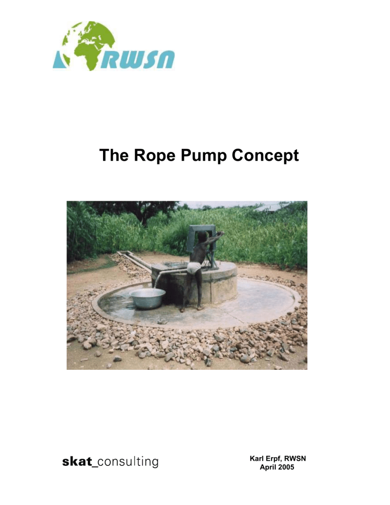
The Rope Pump Concept Karl Erpf, RWSN April 2005 The Rope Pump Concept This document contains a general guide for local Rope Pump manufacture. It addresses a readership interested in this appropriate technology for water lifting who considers introducing the Rope Pump locally. Only generic features of the Rope Pump Concept are explained and hints for successful pump production are given. Information of various sources were collected and put together as a guideline for those who are intending to start local production of Rope Pumps. Main sources were: Practica Foundation of The Netherlands, Bombas de Mecate in Nicaragua, TARATRA in Madagascar, and others. Suggestions for improvements and requests for further information are welcome, and should be sent to RWSN-SKAT at the address given below. First Edition: Author: Copyright: February 2005 Karl Erpf RWSN-SKAT Provided the source is acknowledged, extracts of this publication may be reproduced. Distribution: Skat Consulting Secretariat RWSN, Vadianstrasse 42, CH-9000 St.Gallen, Switzerland Phone: Fax: E-mail: or: URL: Contents 1.0 2.0 3.0 4.0 5.0 6.0 7.0 8.0 9.0 10.0 11.0 General Pump structure Pulley wheel Handle axle Guide Rising main Rope & Pistons Well cover Additional Information Experiences Contacts 2 +41 71 228 54 54 +41 71 228 54 55 mailto:[email protected] mailto:[email protected] http://www.rwsn.ch/ Page No. 3 6 8 9 10 11 12 13 14 18 18 1.0 General The Rope Pump as described in this document is a development that is based on the principle of the ancient Chinese water lifting technology, the “Chain and Washer Pump”. Keeping in mind that many different rope pump designs existed and were in use worldwide, the main development of this easy, cost-effective, and successful technology for water lifting was refined in the 1990 ties in Nicaragua, Central America. Sales figures of the last 10 years in Latin America show that this simple and practical pump has become very popular by the users. They understand the function of the pump and are therefore able to maintain and repair it by themselves. In order to assist in replicating this remarkable success elsewhere, RWSN collected information on this pump technology, and put together a concept paper for project managers and planning personnel involved in the dissemination process. The document is intended to provide general information to anyone interested in this appropriate technology for water lifting, but is primarily aimed at planners, purchasers, and manufacturers (mechanical workshops). To make this guide a useful tool, leading organizations and manufacturers were approached for their assistance in preparing the document. All information provided and specific measurements recommended in “The Rope Pump Concept” were subject to extensive field-testing for many years. RWSN would like to thank Practica Foundation of The Netherlands, Bombas de Mecate in Nicaragua, TARATRA in Madagascar, and many others for the free sharing of information and for their active participation in the production of this document. Like other successful technologies, the Rope Pump is not a “final product” and the development will move on continuously. RWSN will be happy when receiving any additional information on new developments of the technology and additional options for Rope Pumps or suggestion in connection with this concept paper. Technology Transfer Given its cost-benefits and sustainability, funding agencies might be willing to support the technology transfer process. However, before initiating the technology transfer process to other countries it is necessary to establish the technical feasibility and economic viability of the Rope Pump technology under the prevailing conditions. It is important to study the potential market carefully. Once the market has been established, it is crucial to keep in mind that launching a new product needs careful planning and strategic marketing. Pilot projects to establish the Rope Pump in a new market should concentrate on areas where a big potential for Rope Pumps is present, i.e. high density of dug wells. Normally workshops that can produce Rope Pumps are in bigger cities, to keep transportation cost down the potential project area should be near the town. Once the technology has established itself, it will expand into more remote areas. Financial and technical assistance should be designed as a booster function. Such support can help to introduce the technology, but once it is established support from outside should be phased out. Procurement and supply mechanisms need to be adapted to enable users to select and purchase their handpumps and take over full ownership. The selection of a partner for the production is important. A producer of Rope Pumps can be a small engineering plant. However, street side workshops without technical and financial capacity might not have the substance to invest into the creation of a market. Similarly, government owned training schools might have the equipment for production but not the flexibility to engage themselves in successful marketing. The private sector producers have a crucial role to play in the development, manufacturing, promotion, and provision of goods and services to users. Marketing of the product and its application (also for small-scale irrigation) has to be left to the producer and his sales organization. The rope pump should be sold directly to the users. The quality of the locally produced pumps is an additional aspect that needs to be looked at carefully. At first glance, it appears that many small local workshops can easily produce the Rope Pump. No matter how simple the mechanism looks like and how easy and cheap production processes are, the Rope Pump is still a complex machine. To produce an adequate product and to provide a reliable service to the users, manufacturing of this pump requires a relatively high quality standard. Such quality levels are mainly achieved in well-managed engineering production companies. High production volumes also keep down the manufacturing costs and result in low sales prices. 3 Benefits The document is also pointing out other advantages for locally produced Rope Pumps and pump use in general. These benefits include: • Job creation for mechanical skilled people, • Locally manufactured pumps assure that spare parts are locally available, which eliminates the dependency on imported products, • A low cost technology product like the Rope Pump is cheap in price, maintenance, and repair. This is a strong support for the less wealthy population and because of the low price; most of them can afford to procure such a pump type. • Marketing for the Rope Pump should also include strong elements of hygiene and environmental sanitation education, in order to achieve a general improvement of health and living conditions. The improved health situation for water users needs to be pointed out when lifting water with a pump from a closed water source. • Easy access to water with a Rope Pump can indirectly create additional income, when the water is used for growing vegetables, fruits, and other plants or for rearing of animals etc. The Rope Pump Principle: A close loop of a rope with attached pistons, equally spaced, is pulled through pipe, which is immersed in water at its lower end. The pistons entering the rising main pipe are transporting the water upwards until it reaches the top parts with the spout through which it can escape. Pulling the rope is done by turning the pulley wheel, placed at the top. The friction between the pulley-wheel (made of a car tyre) and the rope, pulls the pistons through the rising main pipe and lifts the water to the spout. The pulley-wheel is operated by a crank handle, which is turned in the required direction (see drawing). The handle acts also as the pulley-wheel axle and is located in a pump structure placed on top of the well cover. A guide near the bottom of the well makes sure that the rope with the pistons is entering the rising main smoothly and pistons are prevented from being hooked at the edge of the lower end of the riser pipe. Hand operated Rope Pumps are mostly used for drawing water from dug-wells with depths between 0 to 20 m. However, this pump can also be installed on boreholes (0 to 40 m depth), provided an attachment for leading the rope into the borehole and a smaller guide that fits into the borehole casing is available (see also 9.3). The simplicity of this low cost pump makes it possible that the users can understand how it works and are therefore able to maintain and repair it. An example of complete Rope Pump installed on a dug-well is shown on the next page. 4 The main components are described in the following pages 5 2.0 Pump structure A rigid pump structure is essential to hold the axle of the pulley wheel in its position when the pump is operated, so that the rope is not moving sideways. 2.1 Pump structure Most common pump structures are made of welded steel rods or pipes. Provisions for accommodating the bushings are welded at the upper part and possibilities for locating the rising main and protecting pipes are provided on the sides of the structure. Additional details like the break mechanism, or the provision for fixing a pump cover can also be welded to the structure. Holes in the base of the structure for tightening are only required if the pump structure is not directly cast into the well cover. In places with aggressive waters, corrosion of the steel structure can be a problem. Therefore a corrosion protection like regular painting is essential (if available, hot dip galvanizing would be the best solution). Special attention has to be paid to the height of the wheel axis. The height should be chosen as such that operating the pump handle is ergonomic for the users. Children should also have the chance to operate the pump easily. As an easy role, the height of the wheel axis should be 5 to 10 cm above the average elbow height of the users. Various designs are existing and the location of the pulley wheel can be placed outside of the pump structure (A) or between the bushings (B). If two handles are used on either side of the wheel axis, the pulley wheel is placed between the bushings for equal balance when operated from both sides. Pump structures can be made of various other materials like wooden planks or structures built from bricks and cement (examples see below). Wooden structure Brick & cement structure 6 2.2 Bushings All sorts of bushing systems are possible like different sizes of GI pipes, wooden bushings, ball bearings and even bicycle bearings. Most important is the possibility for easy replacement when worn. • Bushings made from hardwood are cheap, replaceable, and simple to produce. If boiled in oil, they are lasting for a long time. The combination between wooden bushings with a steel axle is ideal. If a wooden axle is used in wooden bushings, the bushings need to be lined with a metal plate or a tin strip cut of a can (see examples below). • Bushings made of GI pipes like any combinations between steel to steel require regular oiling or greasing. For the replacement of bushings, the pump structure needs to be dismantled and new bushings welded to it. • Ball bearings can be used when protected against dust and sand. Availability of required bearing size to be checked. • Bicycle or rickshaw bearings are easy available, but need to be protected against dust and sand. If bicycle bearings with back pedal brake are used, no provision for a brake mechanism is required at the pump structure (extensive testing would be required). Wooden bushing Wooden post with metal plate for locating of axle Wooden bushing Bearing made of GI pipes (see hole for oiling) Wooden bushing lined with a metal plate Ball bearing 2.3 Brake mechanism As soon as pump operation is finished the pulley wheel with handle starts to turn in the opposite direction, because of the weight of the water column, which is forcing the pistons in the rising main downwards until the water in the rising main pipe has drained. To prevent that people are hit by this unexpected handle movement, a brake or blockage system needs to be added. A common brake system is shown here: 7 The brake mechanism should be secure and rigid. If the brake pin can be disengaged for the reason of reducing the rattling sound during operation, the brake mechanism has to be placed as such that it can be re-engaged again by the pump operator without problems. To reduce the noise level of the brake mechanism (rattling sound), a short piece of a PVC hose can be used to cover the brake pin. A simple but most effective system for preventing the handle from turning backwards can be made with a Chain and Hook. One end of the chain is fixed at the pump structure whereas the other end of the chain has a hook attached. After pump operation is finished, the free chain end is put round the handle and the hook is engaged in one of the chain links. The chain in combination with a padlock can also be used for locking the pump if required. 3.0 Pulley wheel The pulley wheel is made of two cuttings from a used car tyre. The two tyre halves are pressed together tightly with wheel clamps, so that the two halves are building a “V” shape. Welded spokes are securing the wheel clamps in position. They also provide the exact location of the hub pipe in the centre of the pulley wheel. The V-shape of the tyre halves create a high friction between the pulley wheel and the rope with pistons, so that no slipping of the rope takes place during operation. 3.1 Pulley halves Pulley halves are cut with a sharp knife from used car tyres of 14” or 15”, preferably rigid tyres from heavy cars or small trucks (see cutting instruction). Another important detail is that the pulley halves are clean and free of burrs or lumps at the inside face, so that the pulley halves can be clamped together tightly and the rope is running in a V-shape (see example below). 3.2 Wheel clamps Wheel clamps are made of flat steel strips, which are bent to clamp the pulley halves tightly in position. 3.3 Spokes The connection between the wheel clamps and the hub pipe of the pulley wheel is done mostly with spokes, similar to a bicycle wheel. 3.4 Hub pipe The hub pipe sits directly on the wheel axle and is usually connected with bolts, so that the moving parts can be dismantled easily if any repair is required. 8 Most important is the centricity of the hub pipe and therefore a welding jig is essential for a successful wheel production. An example of a welding jig is shown here. Wooden structures for holding the pulley halves are possible, but not very common. Welding jig for pulley wheel 4.0 Handle axle In most cases, the handle axle is usually made of galvanized GI pipe, which is bent as such that it serves as the pulley wheel axle on one side and as a crank handle on the other side. 4.1 Crank handle When bending the GI pipe for getting a crank handle, care has to be taken that the bending radius is not smaller than 8 to 10 cm and the pipe is only bent 60°. A simple bending tool for GI pipes should be used, avoiding that the pipe diameter get squashed during bending operation. For ergonomic reasons, the lever height of the crank handle should be 20 cm for 14” wheels or 22 cm for 15” wheels. The length of the handle part should be 23 cm, so that children are able to use both hands for operating the pump. Here is an example for explaining the required crank handle sizes: 4.2 Handle sleeve Most Rope Pumps provide handles with a handle sleeve for more comfort when operating the pump. PVC sleeves cut of scrap pipes is the best-known solution. They can be replaced without problems. Two slotted pipe pieces are required for making a handle; first piece (a) to be snapped onto the handle pipe and the second pipe (b) is solvent cemented on top of pipe “a” (see below). Handle sleeves made of GI pipe (next bigger diameter than the handle pipe) need to be oiled or greased regularly for easier operation. Besides difficulties when replacement is required, users are complaining to get dirty hands from oil or grease when operating the pump. Providing a handle without a sleeve is another possibility, because the surface of a handle will be smoothly polished by the user’s hands after a very short operation time. PVC handle sleeve 9 5.0 Guide Tightening the rope for increasing the friction on the pulley wheel can only be done, if the rope with pistons is guided properly, for entering the rising main at the bottom of the well properly. If a tight rope is pulled for a long time exactly around the same turning spot at the well ground, the guiding material needs to be abrasive resistant. Extensive tests have shown that best results are achieved with glass for the turning point of the rope. Important is also that the whole guiding system for a long rising main pipe is of a certain weight (between 3 to 5 kg), so that the guide is not lifted upwards when the rope is tightened at the pulley wheel. Best results have been achieved with a guiding block cast in concrete. 5.1 Concrete block with glass bottle An easy solution for getting a non-abrasive turning point for the rope is the use of a glass bottle, which needs to be cut and filled with concrete. For the production of the concrete block a simple steel mould is required, in which the glass bottle, the flared inlet pipe and the connecting pipe are located. One hour after the mould has been filled with concrete, the concrete block is pushed carefully out of the mould and is immersed in a water bath for curing (1 week curing time is required). Production details available in the manual of the Madagascar Rope Pump. In wells with a lot of silt deposit at the well ground it is advisable to make sure that position the water inlet is sufficient above the well ground. This can be achieved by attaching an additional stone (stabilizer) to the bottom of the concrete block, to avoid pumping of turbid water. 5.2 PVC Guide box with glass bottle This is a lightweight version of the concrete guide block and can be solvent cemented of various PVC pipes (guide box made of a flattened piece of a large PVC pipe). For shallow wells, the PVC guide box can hang freely at the end of the flared rising main pipe and does not need to be placed at the well ground. For deeper applications, the entire PVC box can be placed in a steel mould for casting a concrete shell around the PVC assembly (see pictures). PVC guide box with glass bottle 5.3 Guide box cast in concrete Metal guide Another easy and simple development is the use of a metal guide for shallow wells. The metal guide is directly attached to the flared end of the rising main pipe and is not placed at the ground of the well (free hanging). The turning point of the rope is made with a GI pipe. This solution is recommended only for non-corrosive water. 10 6.0 Rising main The rising main is made of PVC-U riser pipes with bell-ends, solvent cemented during pump installation. 6.1 Riser pipe When choosing the diameter of the rising main, one has to remember that increasing the pumping head is also increasing the weight of the water column, which makes pumping more strenuous. The only possibility to coop with that increasing weight is to reduce the diameter of the rising main pipe. Recommended Riser Pipe Diameter (nominal diameter = ND) Pumping head range Riser pipe Ø (ND imperial) Riser pipe Ø (ND metric) Upper pipe & spout Ø (ND imperial) Upper pipe & spout Ø (ND metric) 0–6m 1 ½” Ø 5.0 cm 2” Ø 6.3 cm 0 – 10 m 1” 10 – 20 m ¾” Ø 3.2 cm 1 ½” Ø 2.5 cm 1 ½” Ø 5.0 cm Ø 5.0 cm 20 – 40 m* ½” Ø 2.0 cm 1” Ø 3.2 cm * For pump head ranges exceeding 30 m, a pump structure with double handle might be advisable. 6.2 Upper pipe and Spout It is an advantage when the upper pipe including the spout pipe is made of a larger size than the rising main pipe, so that the water reduces its speed and is able to flow out the spout pipe without overflowing the end of the upper pipe (see table above). There are various solutions for connecting the rising main pipe to the upper pipe with spout. Most important is the possibility for disengaging the rising main pipe from the upper pipe, in case a repair is required or a broken rope needs to be retrieved and a new one introduced. Size difference between riser pipe and upper pipe It is advisable to provide a support at the edge of the well cover to avoid a free hanging spout pipe, which could be bent by playing children or due to rough use (specially important for community pumps). Since ultra-violet rays are destroying the structure of plastics, the PVC pipes exposed to sunlight (like the spout) will get brittle with time and tend to brake under tension. This can be avoided when the spout is protected with a layer of enamel paint (preferably dark colours). 6.3 Guide pipe The function of the guide pipe is mainly to protect the rope and to guide it from the pulley wheel back into the well. Therefore, the top face is flared so that no piston is hooked at the entrance of the pipe. 11 7.0 Rope & Pistons The function of the “endless” rope is to pull the pistons through the rising main and to guide them over the pulley wheel and back to the guide at the well bottom. If the rope is pulled with a certain speed (approximately 1 handle revolution per second), a constant flow of water is achieved. 7.1 Rope Almost any type of rope sold at the local markets can be used, but ideal are ropes made of fibres of Polyethylene (PE), Polypropylene (PP), or Polyamide (PA or Nylon). Depending on the size of the rising main, the rope can vary from Ø 4 to Ø 8 mm. Since the rope is the pump component that wears out fastest, regular checking is essential and replacement done before the rope breaks and falls back into the well (difficult to introduce the new rope). 7.2 Pistons Pistons are mainly produced with a simple injection mould, using scrap material like PE, PP, PA or PVC material. However, there are also materials used to produce pistons like wooden pistons produced on a wood turning lathe, rubber pistons punched from a rubber sheet, PVC pistons heat formed with a punch and die from pieces of a scrap pipe etc. Die and punch for heat formed pistons As a general role, at every meter of the rope one piston should be attached (for very deep installations, one piston per 1 ½ m or even 2 m might be enough). Two simple knots (one after and one before) is the simplest way to fix the pistons. Injection moulded pistons Other options for tightening pistons to the rope, see below: Piston with knots Piston with molten rope piece Piston with clover An important factor for a well-functioning Rope Pump is the clearance (play) between the inner diameter (ID) of the riser pipe and the outer diameter (OD) of the piston. Extensive testing in Nicaragua makes it possible to recommend the following general role for clearance between the riser pipes and the pistons: The outside Ø of the pistons used must be 0.5 to 1 mm smaller than the inside Ø of the riser pipes. Situation of piston inside riser pipe 12 8.0 Well cover Although a well with a Rope Pump installed cannot be sealed completely against pollution (openings for the rope) as it is recommended for a drinking water source, it is advisable to protect the water of the well with a cover. For small covers a manhole is an important detail, because it serves to install or take apart the pump and to clean or deepen the well when required. Larger covers should be made of two parts. Other reasons for covering the well are to eliminate the breeding of mosquitoes and other insects and to prevent children, animals, or objects from falling into the well. 8.1 Concrete covers Concrete well covers are regarded as standard. They need to be cast on a flat ground with special care for exact location of the pump structure, the holes for the rising main pipe, the protection pipe, the manhole, and the support of the spout. The concrete covers require reinforcement by iron Re-bars of Ø6 to Ø8 mm with cross spacing of about 15 cm, depending on the diameter of the well cover. Small concrete covers (below Ø120 cm) Small covers can be cast in one piece, but they require a manhole (with a manhole cover) for installing the Rope Pump. The cover thickness should be about 6 to 8 cm and the size of the manhole should not be smaller than 40 x 50 cm. Large concrete covers (above Ø120 cm) Larger covers should be cast in two pieces. The advantage is that no manhole is required and that the weight of a single cover pieces is not too heavy. The matching faces of the two cover halves need to be made exactly, so that well can be closed neatly. It is also advisable to build the matching face with a sloped edge (see examples “a” and “b” below), so that spill- and rainwater is not entering the well. If the pump structure is not directly cast into the well cover, special care is required for providing exact position of pipe holes and bolts for fixing the pump structure. 8.2 Wood Well covers made of wooden planks might be a cheap solution in places where wood is easily available. However, the protection is less secure and regular replacement is required. Wooden covers might be sufficient for family wells, but are not recommended for community wells. 13 9.0 Additional Information 9.1 Pump cover A pump cover as seen in the picture of Bombas de Mecate is important to protect the rope from sunlight (prolongs the life of the rope by a factor 2). In places where the users are requesting a safer water point, there are several options to cover the Rope Pump and protect the well from being contaminated by spill water. It can be a cover that closes the pulley wheel and the pipes (TARATRA), a complete pump cover as seen in the “unknown model” or a cover to seal the complete well (Elephant Pump). TARATRA Madagascar “unknown model” Bombas de Mecate Elephant pump 9.2 Well slab The construction of a well slab around the wellhead is an important contribution to the general hygiene for the community. In addition to discouraging the accumulation of stagnant water at the surface, the slab will help to prevent the contamination of the well by infiltration of dirty water back into the aquifer. The following points are important: a) Slab surfaces with slope towards the drainage and edges of the slab should be raised. b) The slab should be well reinforced with steel wire, to prevent cracking. c) The shape of a slab is not as important as its capacity to drain water away from the well. d) The drain can lead to an area of vegetation (banana plants, vegetables) or to a soak pit. In addition to constructing a well cover, it is important to erect a good fence of locally available materials like wood or stones, to keep animals away from the water point. R ecommended arrangement of a well point. 14 9.3 Other Rope Pump Types A) Rope Pump types designed for installing on drilled boreholes require a special guide at the bottom of the rising main and also a special attachment on the pump structure to guide the rope coming from the pulley wheel smoothly into the borehole casing. This can be made by a deflecting pulley, deviation pipe, a ceramic deflector etc. The minimal casing size in which the special guide can be accommodated is a ND 4” casing (DN 10 cm) with an internal diameter of 9.8 cm). The majority of hand operated Rope Pumps installed on boreholes are set at depths between 0 to 40 m. For deeper installations, it might be advisable to use a motorized Rope Pump. This picture shows a Rope Pump installed on a borehole. The arrow shows the special deflector of glazed ceramic for guiding the rope coming from the pulley wheel into the casing. The top of the casing is closed with a concrete seal and the pump handle has a crank on both sides so that two persons can operate the pump at the same time (deep borehole). The pulley wheel is placed between the bearings for equal balance when operated by two persons. For Rope Pumps installed on boreholes, a special guide is required, which fits in the casing pipe. The turning point of the rope is narrow and therefore a special guide or a smaller glass bottle is required To avoid pumping silt from the end of the borehole, a short piece of a PVC-U pipe can be attached at the lower part of the guide. Guide block for a 4” casing B) Post mounted Rope Pumps are designed to pump water directly in an overhead tank. Therefore, the rising main pipe is raised to the required height and the pulley wheel is mounted to a post. Operation of the pulley wheel at the post is usually done with a second pulley wheel, which is fixed at the ground close to the post. The lower pulley is operated by hand and the turning movement is transformed by the rope that is connected to the upper pulley. 15 Pump installed on borehole C) Rope Pumps driven by an engine are mostly used for pumping drinking water from very deep boreholes (exceeding 40 m) or for irrigation purpose where a large amount of water is required. Petrol / diesel engines as also electrical, solar and wind driven Rope Pumps exist. A few examples are shown below: Rope Pump with diesel engine Rope Pump with electro motor Wind Powered Rope Pump Animal powered Rope Pump 16 9.4 General hints for installation Well cover: Concrete well covers and manhole covers have to be cured for at least one week prior to installation of the Rope Pump. Pump structure, Pulley wheel, and Handle: The complete upper pump mechanism needs to be protected against corrosion (hot dip galvanizing or painting) prior to fixing in (on) the well cover and to assembling of all other components. Twisted Ropes: a) Selected rope to be long enough (final cutting only when installation is completed). b) Introduce the pistons and secure them with a knot at each side (one piston per 1 m). c) During installation, both ends of the rope to be prevented from falling into the well. d) When installation of pump structure and pipes is completed, heat the rope ends with a lighter and twist them while they are still hot to form a compact end. e) Take one rope end, make a loop, and secure the rope end by braiding. f) Place the rope over the pulley wheel, insert the free rope end into the loop, and mark the final rope length. g) Remove the rope from the wheel, cut it at the mark and heat the end to form a compact end. h) Insert the loose rope end again into the loop and secure the second rope end by braiding. i) When braiding is completed, the rope is forced back onto the pulley wheel. j) If the rope is slipping on the pulley wheel when handle is operated, more tightening is required. k) After some days of pump operation, the rope needs to be checked whether it is still tight (elongation might take place because of knots near pistons are tightening during operation). Woven Ropes: If woven ropes are used, the rope needs to be tightened over the pulley wheel for marking the position of the required knot. The free rope ends need to be fixed to the endless rope by winding a string around the rope to tighten the ends. Pipes: a) Prior to installation, all pipes need to be checked that pistons are passing freely. b) All pipe ends to be chamfered on the inside diameter for easy passing of pistons. c) Before jointing starts, the rope with piston has to be introduced in each riser pipe. Make sure that the pistons are in the right direction. d) Jointing of pipes to be done on the ground wherever possible (for shallow wells). e) Do not apply excessive solvent cement to prevent build-up of a bulge when jointing. f) Curing time for solvent cemented joints is at least 6 to 12 hours, before load should be applied. If no time available for curing, lower the concrete block with the joined pipes through the manhole with the help of an additional rope (no load on the freshly jointed pipes). g) When the concrete block is resting at the well ground, introduce the last riser pipe through the pipe hole of the well cover, mark the correct length, cut it with a hacksaw, and make the last joint. h) Upper pipes including spout are normally not solvent cemented, only pushed together, and secured with rubber bands. If a connection mechanism between upper pipes and rising main exists, the upper pipes can be jointed with solvent cement (Madagascar Rope Pump). i) After installation is complete, check the position of the upper pipe and guide pipe, so that the rope is exactly located in the centre of the pipe (make adjustments when required and secure the correct position by tying with rubber bands or by using cement (different procedure are required for wooden well covers). 17 Spout: a) The spout needs to be supported with cement at the edge of the well cover. b) To prevent breakage of spout pipes due to distortion by UV-Rays (sun light), the exposed PVC pipes can be protected by enamel paint. 10.0 Experiences Although the Rope Pump technology seems (and is) simple, there are still many details in production, installation and use that can go wrong. There have been a few discouraging experiences with "just sending" drawings, without a possibility to explain the importance of certain measurements, manufacturing processes, quality control and installation procedures etc. Bad experiences usually result in high costs for rectification and in the end, the whole exercise turns out to be much more expensive than a proper training in production, installation etc. would have been. Minimising or eliminating of bad experiences is in the interest of all parties involved and therefore the advise of the below mentioned organisations should be followed, in order to keep the excellent name and performance of the Rope Pump. 10.0 Contacts When starting with a local production of a Rope Pump it might be helpful if contacts of experienced organisations are available, in case additional information or technical support is required. Practica Foundation Henk Holtslag Hyacinthweg 23, 2565 RE The Hague, The Netherlands Phone: +31 70 368 70 13 E-mail: mailto:[email protected] Homepage: www.ropepumps.org or: www.practicafoundadtion.nl Bombas de Mecate Technology Transfer Division Henk Alberts, Km. 29, Carretera Vieja a Léon P.O. Box 3352 Managua, Nicaragua Phone: +505 2 78 40 45 Fax: +505 2 78 40 45 E-mail: mailto:[email protected] Homepage: www.ropepump.com TARATRA Monsieur Arsène Raveloson Lot II L 73 bis Ankadivato 101 Antananarivo Madagascar Phone: +261 20 22 789 39 Fax: +261 20 22 298 19 E-mail: mailto:[email protected] Personal e-mail: mailto:[email protected] SKAT (please see contact address on page 1) 18
