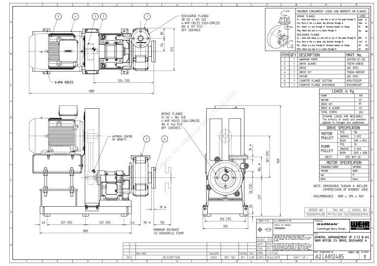
2 1 4 3 5 6 7 8 9 10 MAXIMUM CONCURRENT LOADS AND MOMENTS ON FLANGES My 4 5 3 2 DISCHARGE FLANGE 1 38 I/D A 165 O/D X OFF CENTRES 89 Fz B 4-_19 HOLES EQUI-SPACED ON A 127 PCD Fxy= Force Mxz Mz = About z-z axis through A. Torsional moment on flange. any axis in x-y plane through A. Fy A = Axial load along y-y axis into or out of the pump through B Fxz= Force X 524 Y COG C N 1300 N 95 Nm 190 Nm 880 N 440 N 28 Nm 56 Nm = About y-y axis through B. Torsional moment on flange. My Mz in the x-z plane. Any direction through B. Mxz= About any axis in x-z plane through B. ITEM QTY DESCRIPTION 6-_16 HOLES 2600 PART No. 1 WARMAN PUMP AH215B-CCC-B2 2 1 DRIVE GUARD TB278-330E02 3 1 DRIVE SEE SPEC. 4 1 DRIVE 5 1 MOTOR SEE SPEC. 6 1 COUNTER FLANGE SUCTION B15417SE02P 7 1 COUNTER FLANGE DISCHARGE B15418SE02P KIT TB260-160E02P LOADS INTAKE FLANGE 51 I/D 184 O/D PUMP 100 MOTOR 67 KIT DRIVE & GUARD 81 TOTAL (STATIC) 293 The effects of loads and moments applied to flanges are additional. MOTOR APPROX CENTRE PULLEY * 6 PUMP PULLEY 19 969 56 COG 337 * WEIGHT IN KG OFFICE 2 3 4 BUSH 2012 E x _28 MANUFACTURER SIEMENS FRAME 160M kW 11 RPM 2940 F 1089 x 395 x 969 NO TAG G TITLE 4 APP: R.M. 3 2 CHK: R.G. FIRST ISSUE DESCRIPTION 6 DATE 7 REF of the copyright and all confidential information in this drawing. NO 8 9 GENERAL ARRANGEMENT OF 2-1.5 B-AH, 160M MOTOR, ZV DRIVE, DISCHARGE A The drawing must not be copied in whole or in part, in any form or by any means, and the information in it must not be disclosed to any person, or used for any purpose other than the specific purpose for which it has been provided, without the prior written consent of the Company. Y.UYSAL R.G. DRN: Y.UYSAL BY CHK DATE: 10JUL2019 10JUL2019 5 3 SPZ TODMORDEN SCALE: 1:5.5 1 GROOVE OF ORIGIN : Copyright © Weir Minerals Europe Limited. 2019 Weir Minerals Europe Limited ("the Company") is the owner REV 112 ALL DIMENSIONS IN MM TO DISMANTLE PUMP 1 PCD x _42 150 MINIMUM DISTANCE H 1610 NO SERIAL NO 1000165914/80 PP-PU-022-133 100000035934 395 800 BUSH 20 * 356 CRS 115 3 SPZ SPZ 1077 (3) ENCUMBRANCE : ORDER 144 GROOVE NOTE. DIMENSIONS SHOWN * INCLUDE COMPRESSION OF RUBBER JOINT G 337 CRS 106 MOTOR SPECIFICATION F 337 CRS PCD BELTS 184 * 367 CRS E 63 D DRIVE SPECIFICATION OFF CENTRES 19 45 DYNAMIC LOADS ARE NEGLIGIBLE 4-_19 HOLES EQUI-SPACED ON A 146 PCD OF GRAVITY C in Kg DRIVE 7 B 1 1089 D A DISCHARGE FLANGE: X 372 in the x-y plane. Any direction through A. Mxy= About Y 114 = Axial load along z-z axis into or out of the pump through A Z Mxy B LOAD INTAKE FLANGE: X Z 12 11 H SHEET SIZE DRAWING SHEET 10 1 OF 1 No SHEET GB A2 A812485 11 REVISION 0 12
