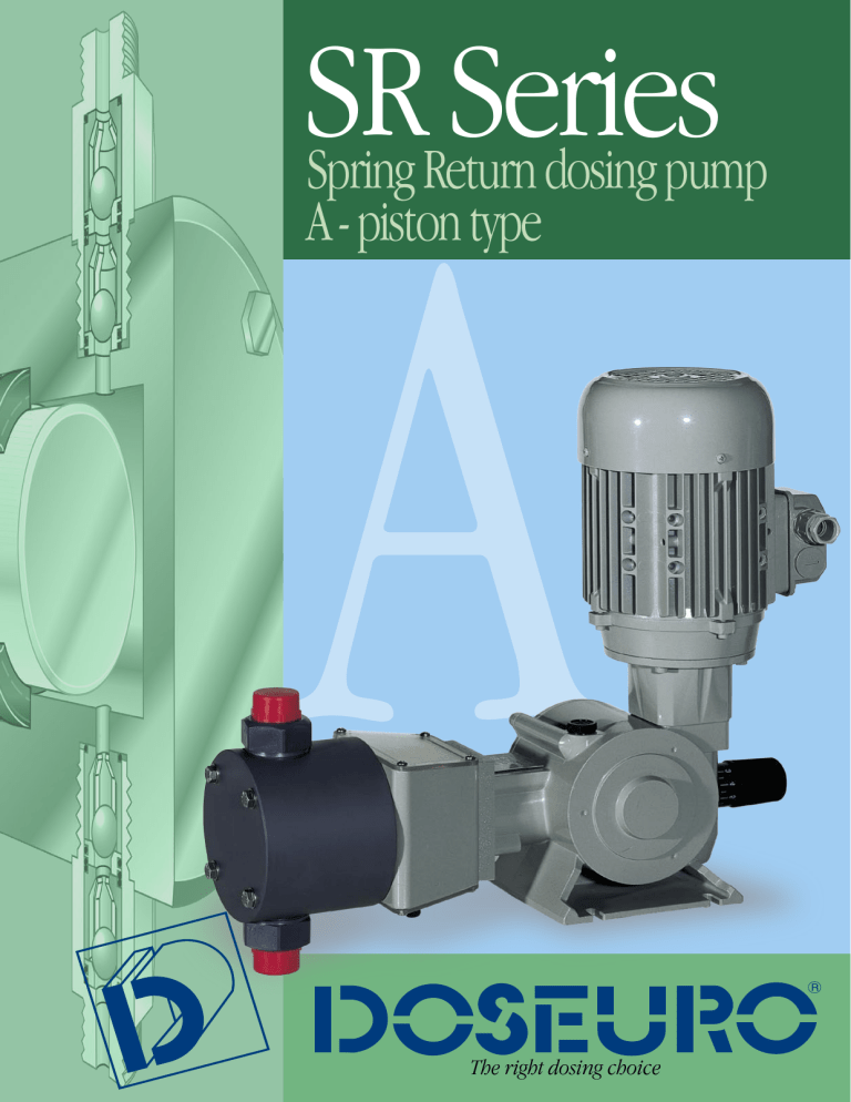
SR Series Spring Return dosing pump A - piston type The right dosing choice SR Series MAIN ELEMENTS TO SUPPORT OUR PRODUCTS Versatility Different piston sizes are available to suit different applications, starting from 0,8 until 1458 l/h Reliability The high degree of accuracy and reproducibility with high quality materials selected make the piston pump SR series to assure the maximum reliability. Quality The best performance for the applications is achieved by optimal selection of plunger material and seal design. FEATURES Piston metering pumps are suitable for use when: - The dosed liquid is a non abrasive solution - A drip proof system is not essential - High pressure is required Each pump is fitted a standard gearbox reduction system and with a vertical mounted B14 shaped electric motor in accordance with UNEL-MEC specifications. The motor power range is from 0.18 Kw up to 0.75 KW as the European standard: 3 phase voltages of 230/400V @ 50/60Hz, 4 pole and 1 phase voltages of 230/50-60 Hz or 110/60 Hz. As motors conform to UNEL-MEC specifications, there are many alternative option available, including different voltages, insulation class and special explosion proof versions. Spring Return Plunger Dosing Pumps Type A and AP-A The gearbox is a standard wormwheel reduction system with all bearings supported within a fully lubricated gearbox. The mechanism for variation of the stroke length a positive stroke spring return that is operated by an eccentric. PUMPING HEADS Pumping heads are made in standard executions: S.S. 316 or PVC A wide range of other materials like HASTELLOY, ALLOY, PTFE, PVDF, PP are according to the liquid to be dosed. Piston gaskets are of the lip type design and are available in a wide range of materials (FPM, EPDM, SILICONE, ADIPRENE) and also in PTFE packing. Standard liquid handled maximum temperature - 90° C with S.S. 316 pump head - 40° C with PVC pump head Jacketed pump head for either cooling or heating are available to suit requirements. Piston glandling arrangements can be supplied with water washed seals to continuously flush the piston. PLUNGERS There are made in S.S. 316 or Ceramics SUCTION AND DISCHARGE CONNECTIONS Normally are threaded, but they can be supplied also flanged. All the pumps have a ball valve standard: single and double balls by the function of the piston diameter or the material execution. STROKE ADJUSTMENT Flow rate adjustment is possible while running or at standstill. The movement of the piston is based on a precise reciprocating gearbox, which provides an exact volumetric displacement. Stroke adjustment can be carried out: - Manual: by a linear micrometer screw - Electrical: via servo motor with 4-20 mA signal upon request interface PROFIBUS or other BUS - Pneumatic: by a pneumatic servo control with signal from 3 to 15 PSI MULTIPLE HEADED PUMPS Different multiple heads units are available on request. Each pumping element has independent adjustment while running or at standstill. HIGH PRESSURE EXECUTION These pumps use the same crank mechanism of the pumps “A” type, but the difference is on the hydraulic part that must be suitable to satisty very hard requirements. “A” series piston pumps are available in different sizes: - A 125 N Piston stroke 12.5 mm - A 175 N Piston stroke 17.5 mm - A 250 N Piston stroke 25 mm - A 350N Piston stroke 35 mm For these types, 11 different piston sizes are available to suit different applications for capacity and pressure. SR Series SOME STANDARDS EXECUTIONS FOR PISTON PUMPS EXECUT. 11 13 17 19 20 21 32 41 PUMPHEAD S.S. 316 PVC S.S. 316 S.S. 316 PVC S.S. 316 S.S 316 S.S 316 FPM = fluoroelastomer S.S 316 = stainless steel 316 Difference executions on request PISTON S.S. 316 CERAMIC CERAMIC S.S. 316 S.S. 316 S.S. 316 S.S 420 CERAMIC VALVE (ball) S.S. 316 PYREX S.S. 316 S.S. 316 PYREX S.S. 316 S.S 316 S.S. 316 C.O. = Chromium Oxide VALVE SEATS S.S. 316 PVC S.S. 316 S.S. 316 PVC S.S. 316 S.S. 316 S.S. 316 PISTON GASKETS NBR FPM FPM FPM NBR PTFE AU AU PP/FRV = polypropylene + glass fibber Glossary and numbering system to identify pumps type A 1st group 125N 2nd group 38/ 3rd group “A” type piston dosing pump Stroke length Piston diameter in mm F 4th group Reduction ratio group (N° of piston strokes/min) F(1/24) - B (1/12) 11 5th group DV 6th group Materials in touch with the fluid Not standardspecial code In case of pumps supplied without motor add: W/M GENERAL OVERALL DIMENSIONS 350 90 100 127 127 C 70 75 120 120 D 75 72 70 70 E 378 410 450 455 F 90 90 154 154 G 70 70 130 130 H 115 125 157 157 I 65 65 102 102 L 7 7 9 9 M 140 160 194 200 N 32 32 60 60 O 80 78 78 78 H I O 75 B G 75 F 250 68 E 175 57 D 125 A L A B N C M General dimensional quote are indicative and adverted to the maximum acceptable pump dimension Spring Return Plunger Dosing Pumps Type A 125N TECHNICAL CHARACTERISTICS Reducer ratio Pump type (*1) A-125N-11 A-125N-18 A-125N-25 A-125N-30 A-125N-38 A-125N-47 SPM (*1) L/1’ Max Press. (*3) L/h 60 Hz 50 Hz 60 Hz 50 Hz 60 Hz 58 70 0,013 0,017 0,8 1,0 C 96 116 0,022 0,027 1,3 1,6 B 116 0,027 SS 316 PVC SS 316 Motor Features PVC ø mm Real piston Stroke Length Net Weights Kg (*5) SS 316 PVC 6 8,5 7,5 11.11 8,5 7,5 17.46 8,5 7,5 8,5 7,5 30.16 8,5 7,5 9 38.1 10 8,2 5.5 47.63 10 8,4 1,6 I 35 42 0,04 0,048 2,4 2,8 F 58 70 0,066 0,080 4 4,8 C 96 116 0,110 0,133 6 8 B 116 I 35 42 0,1 0,120 6 7,2 F 58 70 0,166 0,200 10 12 C 96 116 0,273 0,330 16 20 B 116 I 35 42 0,221 0,264 13,2 15,8 F 58 70 0,366 0,440 22 26,4 C 96 116 0,604 0,733 36 44 B 116 I 35 42 0,311 0,374 18,7 22,4 F 58 70 0,516 0,620 31 37,2 C 96 116 0,854 1,033 51 62 B 116 I 35 42 0,502 0,600 30 F 58 70 0,833 1,000 50 60 C 96 116 1,373 1,660 82 100 B 116 I 35 42 0,784 0,940 47 56 F 58 70 1,300 1,560 78 93,6 C 96 116 2,150 2,600 129 156 B 116 0,133 20 8 0,330 10 20 0,733 20 1/2” G.m. 44 1,033 14 Kw 0.18 3 Ph ~1400 rpm or Kw 0.18 1 ph ~1400 rpm 25.4 12.5 mm 62 1,660 2,600 Connections (*4) Kg/cm2 50 Hz F A-125N-6 Capacity (*2) 36 100 156 (*1) Piston strokes number during 1 minute with 4 poles installed motor (1400 rpm) I = Reducer ratio 1 : 40 = 35 strokes at 50 Hz / 42 strokes at 60 Hz F = Reducer ratio 1 : 24 = 58 strokes at 50 Hz / 70 strokes at 60 Hz C = Reducer ratio 1 : 14,5 = 96 strokes at 50 Hz / 116 strokes at 60 Hz B = Reducer ratio 1 : 12 = 116 strokes at 50 Hz / not suitable (*2) The indicated capacity value is subject to change due to the working pressure, dosed liquid, viscosity and installation asset. (*3) High pressures are available (*4) Different ranges of connections are available on request (*5) The weight is approximate and it is the value of the pump fitted with a totally enclosed fan- cooled outdoor motor. (6) The pumps can be supplied with accessories if requested (7) The pumps are epoxy coated RAL 7030 SR Series Type A 175N TECHNICAL CHARACTERISTICS Reducer ratio (*1) SPM Pump type (*1) A-175N -6 A-175N -11 A-175N -18 A-175N -25 A-175N -30 A-175N -38 A-175N -47 A-175N -54 A-175N -64 50 Hz Max Press. (*3) Kg/cm2 Capacity (*2) L/1’ L/h 60 Hz 50 Hz 60 Hz 50 Hz 60 Hz F 70 84 0,021 0,026 1,3 1,56 C 96 116 0,029 0,035 1,7 2,11 B 120 0,036 SS 316 0,37 KW PVC 0,25 KW PVC 0,37 KW // // SS 316 ø mm Motor Features PVC Real piston Stroke Lenght Net Weights Kg (*5) SS 316 PVC 6 11 10 11.11 11 10 17.46 11 10 25.4 11 10 11 10 38.1 12 10,5 2,2 F 70 84 0,100 0,120 6 7,2 C 96 116 0,133 0,160 8 9,6 B 120 F 70 84 0,283 0,340 17 20,4 C 96 116 0,400 0,480 24 28 B 120 0,166 10 0,500 20 30 F 70 84 0,616 0,740 37 44,4 C 96 116 0,853 1,024 51 61,4 B 120 1,066 10 1/2 “ G.m. 64 F 70 84 0,866 1,400 52 62,4 C 96 116 1,200 1,440 72 86 B 120 1,500 F 70 84 1,383 1,660 83 99,6 96 116 1,920 2,304 115 138 B 120 2,400 20 13 20 8.5 13 8.5 10 47.63 12 10,5 6.5 10 6.5 10 53,98 15,8 12,4 63.5 16,4 12,5 144 F 70 84 2,166 2,600 130 156 C 96 116 3,013 3,615 180 216 B 120 3,766 Kw 0.25 or Kw 0.37 3 Ph ~1400 rpm or Kw 0.25 or Kw 0.37 1 Ph ~1400 rpm 20 90 C 30.16 17.5 226 F 70 84 2,800 3,360 168 201,6 C 96 116 3,866 4,640 232 278 B 120 F 70 84 3,933 4,720 236 283,2 C 96 116 5,440 6,528 326 391 B 120 4,830 6,800 SS 316 0,25 KW Connections (*4) 290 3/4” G.m. 4.5 7 4.5 7 408 (*1) Piston strokes number during 1 minute with 4 poles installed motor (1400 rpm) F = Reducer ratio 1 : 20 = 70 strokes at 50 Hz / 84 strokes at 60 Hz C = Reducer ratio 1 : 14,5 = 96 strokes at 50 Hz / 116 strokes at 60 Hz B = Reducer ratio 1 : 11,5 = 120 strokes at 50 Hz / not suitable (*2) The indicated capacity value is subject to change due to the working pressure, dosed liquid, viscosity and installation asset. (*3) High pressures are available (*4) Different ranges of connections are available on request (*5) The weight is approximate and it is the value of the pump fitted with a totally enclosed fan- cooled outdoor motor. (6) The pumps can be supplied with accessories if requested (7) The pumps are epoxy coated RAL 7030 Spring Return Plunger Dosing Pumps Type A 250N and A 350N TECHNICAL CHARACTERISTICS Reducer ratio (*1) Pump type Strokes number /1’ (*1) A-250N-25 A-250N-38 A-250N-47 A-250N-54 A-250N-64 A-250N-76 A-250N-89 A-350N-89 50 Hz Max Press. (*3) Kg/cm2 Capacity (*2) L/1’ L/h 60 Hz 50 Hz 60 Hz 50 Hz 60 Hz F 56 67 0,716 0,860 43 51,6 C 96 116 1,228 1,474 73 88 B 112 1,433 20 SS 316 PVC KW PVC KW KW 0,55 0,75 SS 316 0,75 // // F 56 67 1,600 1,920 96 115,2 96 116 2,743 3,290 164 197,5 B 112 F 56 67 2,500 3,000 150 180 C 96 116 4,285 5,142 257 308 B 112 3,200 Motor PVC // 86 C 20 20 // // 17 20 10 10 300 F 56 67 3,200 3,840 192 230,4 C 96 116 5,485 6,582 329 395 B 112 6,400 3/4” G.m. 13 17 10 10 9,5 12 9.5 10 6,5 8,6 6.5 8,6 4,8 6,3 4.8 6,3 // 4 // 4 384 F 56 67 4,433 5,320 266 319,2 C 96 116 7,600 9,120 456 547,2 B 112 8,860 532 F 56 67 6,383 7,660 383 459,6 C 96 116 10,943 13,131 656 787,8 B 112 12,760 766 F 56 67 8,683 10,420 521 625,2 C 96 116 14,885 17,862 893 1071,7 B 112 17,360 Real piston Stroke Lenght Net Weights Kg (*5) SS 316 PVC 25,4 21 // 38,1 23 17 47,63 23 17 23.5 17.5 63,5 25.5 20 76,2 26 20 88,9 29 20 35 24 1/2 “ G.m. 192 5,000 Kw 0.55 or Kw 0.75 3 Ph ~1400 rpm or Kw 0.55 or Kw 0.75 1 ph ~1400 rpm 1” G.m. 53,98 25 1042 F 56 67 12,150 14,566 729 874 C 96 116 20,816 24,966 1249 1498 B 112 24,300 SS 316 KW 0,55 ø mm Connections (*4) 1458 (*1) Piston strokes number during 1 minute with 4 poles installed motor (1400 rpm) F = Reducer ratio 1 : 25 = 56 strokes at 50 Hz / 67 strokes at 60 Hz C = Reducer ratio 1 : 14,5 = 96 strokes at 50 Hz / 116 strokes at 60 Hz B = Reducer ratio 1 : 12,5 = 112 strokes at 50 Hz / not suitable (*2) The indicated capacity value is subject to change due to the working pressure, dosed liquid, viscosity and installation asset. (*3) High pressures are available (*4) Different ranges of connections are available on request (*5) The weight is approximate and it is the value of the pump fitted with a totally enclosed fan- cooled outdoor motor. (6) The pumps can be supplied with accessories if requested (7) The pumps are epoxy coated RAL 7030 1 1/2” G.m. Kw 0.75 88,9 35 SR Series Type AP-A 125N Reducer ratio (*1) Pump type (1*) AP A-125N - 8 AP A-125N - 12 AP A-125N - 14 AP A-125N - 16 SPM Max Press. (*3) Kg/cm2 Capacity (*2) L/1’ L/h SS 316 50 Hz 60 Hz 50 Hz 60 Hz 50 Hz 60 Hz I 35 42 0,019 0,022 1,1 1,3 F 58 70 0,031 0,036 1,9 2,2 C 96 116 0,051 0,061 3,1 3,7 B 116 I 35 42 0,044 0,052 2,6 3,1 F 58 70 0,073 0,086 4,4 5,2 C 96 116 0,120 0,143 7,2 8,6 B 116 I 35 0,061 Kw 018 Kw 025 95 250 88 170 Connections (*4) Motor features SS 316 Real piston Ø mm Stroke length mm Net weights Kg (*5) SS 316 8 9 12 9 3,7 0,143 8,6 42 0,060 0,070 3,6 F 58 70 0,100 0,116 6 7 C 96 116 0,165 0,196 9,9 11,8 B 116 I 35 42 0,078 0,094 4,7 F 58 70 0,130 0,155 7,8 9,4 C 96 116 0,215 0,256 13 15,6 B 116 0,196 1/2 “ G.m. 4,2 65 125 50 96 Kw 0,18 3 ph ~ 1400 rpm or kw 0,18 ~ 1400 rpm 1 ph 12,5 14 9 16 9 11,8 0,256 5,6 15,6 (*1) Piston strokes number during 1 minute with 4 poles installed motor (1400 rpm) I = Reducer ratio 1 : 40 = 35 strokes at 50 Hz / 42 strokes at 60 Hz F = Reducer ratio 1 : 24 = 58 strokes at 50 Hz / 70 strokes at 60 Hz C = Reducer ratio 1 : 14,5 = 96 strokes at 50 Hz / 116 strokes at 60 Hz B = Reducer ratio 1 : 12 = 116 strokes at 50 Hz / not suitable at 60 Hz Type AP-A 175N Reducer ratio (*1) Pump type (1*) AP A - 175N -12 AP A - 175N -14 AP A - 175N -16 AP A - 175N -18 L/1’ L/h SS 316 50 Hz 60 Hz 50 Hz 50 Hz 50 Hz 60 Hz 70 84 0,055 0,066 3,3 3,9 C 96 116 0,075 0,090 4,5 5,4 B 120 F AP A - 175N -8 SPM Max Press. (*3) Kg/cm2 Capacity (*2) 0,093 95 250 95 233 95 171 75 131 59 102 Motor features SS 316 Real piston Ø mm Stroke length mm Net weights Kg (*5) SS 316 8 11 12 11 5,6 F 70 84 0,123 0,147 7,4 8,8 C 96 116 0,168 0,201 10,1 12,1 B 120 0,210 12,6 F 70 84 0,188 0,225 11,3 13,5 C 96 116 0,256 0,307 15,4 18,4 B 120 0,321 19,3 F 70 84 0,245 0,294 14,7 17,6 C 96 116 0,335 0,402 20,1 24,1 B 120 0,420 1/2” G.m. Kw 0,25 3 ph ~ 1400 rpm or kw 0,25 ~ 1400 rpm 1 ph 14 17,5 11 16 11 18 11 25,2 F 70 84 0,280 0,336 16,8 20,1 C 96 116 0,383 0,459 23 27,6 B 120 0,476 Kw 025 Kw 037 Connections (*4) 28,6 (*1) Piston strokes number during 1 minute with 4 poles installed motor (1400 rpm) F = Reducer ratio 1 : 20 = 70 strokes at 50 Hz / 84 strokes at 60 Hz C = Reducer ratio 1 : 14,5 = 96 strokes at 50 Hz / 116 strokes at 60 Hz B = Reducer ratio 1 : 11,5 = 120 strokes at 50 Hz / not suitable at 60 Hz High pressure Spring Return Plunger Dosing Pumps Type AP-A 250N Reducer ratio (*1) Pump type SPM (1*) AP A 250N -12 AP A 250N - 14 AP A 250N - 16 AP A 250N - 18 AP A 250N - 20 AP A 250N - 22 AP A 250N - 25 50 Hz Max Press. (*3) Kg/cm2 Capacity (*2) L/1’ 60 Hz 50 Hz 60 Hz L/h SS 316 50 Hz 60 Hz F 56 67 0,141 0,169 8,5 10,2 C 96 116 0,241 0,289 14,5 17,4 B 112 0,281 Kw 0,75 Motor features SS 316 Real piston Ø mm Stroke length mm Net weights Kg (*5) SS 316 250 12 20 250 14 20 16 22 16,9 F 56 67 0,193 0,231 11,6 13,9 C 96 116 0,330 0,396 19,8 23,8 B 112 0,385 23,1 F 56 67 0,251 0,301 15,1 18,2 C 96 116 0,430 0,516 25,8 31 B 112 0,500 95 196 30 F 56 67 0,320 0,384 19,2 23 C 96 116 0,548 0,657 32,9 39,4 B 112 0,638 155 38,3 F 56 67 0,395 0,474 23,7 28,4 C 96 116 0,676 0,811 40,6 48,7 B 112 0,788 126 1/2” G.m. Kw 0,55 or Kw 0,75 3 ph ~ 1400 rpm or kw 0,55 or Kw 0,75 ~ 1400 rpm 1 ph 18 25 22 20 22 47,3 F 56 67 0,478 0,573 28,7 34,4 C 96 116 0,820 0,984 49,2 59 B 112 0,956 79 104 22 22 61 80 25 22 57,4 F 56 67 0,616 0,740 37 44,4 C 96 116 1,058 1,270 63,5 76,2 B 112 1,235 Kw 0,55 Connections (*4) 74,1 (*1) Piston strokes number during 1 minute with 4 poles installed motor (1400 rpm) F = Reducer ratio 1 : 25 = 56 strokes at 50 Hz / 67 strokes at 60 Hz C = Reducer ratio 1 : 14,5 = 96 strokes at 50 Hz / 116 strokes at 60 Hz B = Reducer ratio 1 : 12,5 = 112 strokes at 50 Hz / not suitable at 60 Hz (*2) The indicated capacity value is subject to change due to the working pressure, dosed liquid, viscosity and installation asset. (*3) High pressures are available (*4) Different ranges of connections are available on request (*5) The weight is approximate and it is the value of the pump fitted with a totally enclosed fan- cooled outdoor motor. (6) The pumps can be supplied with accessories if requested (7) The pumps are epoxy coated RAL 7030 Accessories Safety relief valves Type Pump capacity Connections TS-10 200 l/h 3/8” or 1⁄2” TS-13 400 l/h 1⁄2” G.F TS-21 1000 l/h 1” G.F Body PVC or S.S. 316 PULSATION DAMPENERS * S.S. 316 Relief - Safety valve setting pressure: max 40 kg/cm2 (588 Psi) higher pressures are available on request. PVC Relief safety valve setting pressure: max 10 kg/cm2 (145 Psi). For higher setting pressures consult our technical dept. Pulsation dampeners Type: HSTX Body in S.S.316, composed of two parts assembled by a special hosing that under dynamic pressures tends to close itself. Diaphragms are compatible to the liquid used. Built in accordance with ASME VIII° Div. 1 rules. Type: HSTPVC Body in PVC, composed of two parts assembled by a special hosing that under dynamic pressures tends to close itself. Maximum temperature: + 50 °C. Diaphragms are compatible with the process liquid. Each metering pump can be supplied with accessories in order to improve the operation and accuracy of the units. The benefits of fluid control assure - Increase efficiency and pump life - Decrease maintenance and operation costs The control of fluid dynamics is essential to ensure efficient and safe use of process systems. Uncontrolled fluid in motion can physically destrois. A pumping system including the pumping, valves, meters, back pressure valves, inline instrumentation and equipment. 1.- FILTERS We suggest to install filters (on the suction pipe) to keep back impurities that can be presented on liquid to be dosed or coming from pipeline system. The use of filters assures a trouble-free dosing. 2.- SAFETY VALVES Safety valves are designed to protect the pump and chemical feed system from over pressure damage caused by defective equipment or a blockage in the chemical feed line. Relief valves and back pressure valves SAFETY VALVES BACK PRESSURE VALVES FILTERS Type Pump Capacity Connections VSC-6 90 l/h 1⁄2” G.F VSC-10 230 l/h 1⁄2” G.F VSC-14 420 l/h 3⁄4” G.F VSC-22 1050 l/h 1” G.F Body PVC or S.S. 316 Diaphragm PTFE/NBR * Relief valve setting pressure. 3/10 kg/cm2 (44/145 Psi) Back pressure valve setting pressure: 1/3 kg/cm2 (15/44Psi) G.F.= Cylindrical, Female Polyethylene tanks suitable to be fitted with metering pump on its top 3.- BACK PRESSURE VALVES Back pressure valves apply positive discharge pressure to a metering pump system to prevent siphoning and eliminate varying downstream pressure. 4.- PULSATION DAMPENER Metering pumps have a pulsating flow. Both spring return plunger dosing pumps and quick closing valves start and stop fluids that are in motion. Spring return plunger dosing pumps derive their pumping action by capturing a given amount of fluid in a chamber and pushing it out the pump’s discharge. Each pump cycle includes a suction stroke during the fluid flow is stopped. This pumping action produces an acceleration/deceleration of the fluid, creating units of uncontrolled energy, resulting in PULSATION, observed as pressure spikes. Pulsation dampener is required for two reasons: - Two reduce high, non- permissible pressure fluctuations. - To create a nearly continuous flow. Our range of production also includes: SR series: Hydraulic diaphragm dosing pumps “B”, “BR” and “SD” types Mechanical diaphragm dosing pumps “D” and “FM” types PDP series: Positive displacement dosing pump “AI” and ”SDI” types High pressure positive displacement dosing pump “AP-AI” types SDP series: Solenoid dosing pumps “S” type Solenoid dosing pumps “GA” type H series: Automatic plants for dissolution and preparation of powder polyelectrolytes “HA”, “HB” types EM series: HEAD OFFICE Via G. Carducci 141 20093 Cologno Monzese (MI) Italy Tel.: +39 02 27301324 Fax: +39 02 26700883 e-mail: [email protected] www.doseuro.com DOSEURO (UK) LTD. Unit 8, East Road Industrial Estate Sleaford, Lincolnshire NG34 7EH Tel.: +44 1529 300045 Fax: +44 1529 410967 e-mail: [email protected] www.doseuro.co.uk The right dosing choice XNME0PCAG000G0106 Electric mixers for chemical mixing “DMT”, “DEM”, “DRV” and “DRC” types
