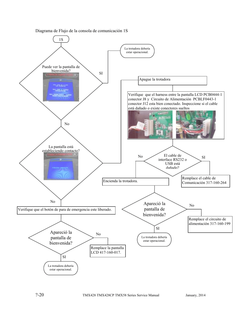
Diagrama de Flujo de la consola de comunicación 1S 1S La trotadora debería estar operacional. Puede ver la pantalla de bienvenida? SI Apague la trotadora Verifique que el harness entre la pantalla LCD PCB0444-1 conector J8 y Circuito de Alimentación PCBLF0443-1 conector J12 esta bien conectado. Inspeccione si el cable está dañado o existe conectores sueltos No La pantalla está estableciendo contacto? El cable de interface RS232 o USB está dañado? No Remplace el cable de Comunicación 317-160-264 Encienda la trotadora. No Verifique que el botón de para de emergencia este liberado. SI Apareció la pantalla de bienvenida? No Remplace el circuito de alimentación 317-160-199 SI Apareció la pantalla de bienvenida? No Remplace la pantalla LCD 417-160-017. La trotadora debería estar operacional. . SI La trotadora debería estar operacional. ?-20 TMX428 TMX428CP TMX58 Series Service Manual January, 2014 Circuito de Alimentación Error Código 9 Diagrama de Flujo 1R SI 1R 1I El led rojo D13 flashea 9 veces con una pausa de 4 seg. En el circuito de alimentación PCBLF0443-1? No Esta el led rojo D13 flasheando en el circuito de alimentación PCBLF0443-1? No La trotadora debería estar operacional. SI Apague la trotadora Está dañado el cable RS232 o USB de interface? Revise si existe daño en el cable de interface entre la trotadora & Sistema de esfuerzo. No No Permanece encendido el led rojo D13 en el circuito de alimentación PCBLF0443-1? SI Remplace el cable de Interface. Encienda la trotadora 1I Presione start en el panel de la trotadora. Aumente la velocidad hasta 10 mph Con la trotadora a 10 mph durante 1 minuto permanece el led rojo D13 encendido? SI La trotadora debería estar operacional. No 1I Circuito de Alimentación Error Código 3 Diagrama de Flujo 10 Consulte a fábrica para solucionar el problema. January, 2014 TMX428 TMX428CP TMX58 Series Service Manual ?-19 Circuito de Alimentación Error Código 8 Diagrama de Flujo 1Q SI 1Q 1I El led rojo D13 flashea 8 veces con una pausa de 4 seg. En el circuito de alimentación PCBLF0443-1? No Esta el led rojo D13 flasheando en el circuito de alimentación PCBLF0443-1? No La trotadora debería estar operacional. SI Apague la trotadora Verifique que el harnes entre Drive PC2303-012N y circuito de alimentación PCBLF0443-1 está bien conectado. Esta el harnes bien conectado? No Conecte el harness. SI Verifique que el harnes entre el Motor PMC5FA-00101-03 y Drive PC2303-012-N está bien conectado. Esta el harnes bien conectado? No Conecte el harness. SI Presione inicio en el panel del control de la trotadora La trotadora empezó a correr? Remplace el Drive No PC2303-012-N Regrese la trotadora para servicio ?-18 Encienda la trotadora SI SI Permanece encendido el led rojo D13 en el circuito de alimentación PCBLF0443-1? No 1I TMX428 TMX428CP TMX58 Series Service Manual January, 2014 B A Encienda la trotadora Verifique que el espacio o brecha del sensor de velocidad de la rueda magnética es un 1/16” y el conector está bien sujeto en J10 del circuito de alimentación PCBLF0443-1. Permanece encendido el led rojo D13 en el circuito de alimentación Verificar que cuando el imán del volante pasa por el sensor de velocidad el led D10 LED del circuito de alimentación PCB KF0443-1 el led rojo luces está encendido y se apaga después de que la velocidad no está No PCBLF0443-1? 1I SI Presione start en el panel de la trotadora. Aumente la velocidad hasta 10 mph Esta el led rojo D10 del circuito de alimentación PCBLF0443-1 flasheando ON & Off cuando pasa el magneto? SI Con la trotadora a 10 mph está el led rojo D13 encendido? No Remplace el circuito de alimentación 317-160-199 No SI La trotadora debería estar operacional. Remplace el circuito PC2303-012-N 317-160-199 January, 2014 TMX428 TMX428CP TMX58 Series Service Manual ?-17 Circuito de Alimentación Error Código 7 Diagrama de Flujo 1P SI 1P 1I El led rojo D13 flashea 7 veces con una pausa de 4 seg. En el circuito de alimentación PCBLF0443-1? No Esta el led rojo D13 flasheando en el circuito de alimentación PCBLF0443-1? No La trotadora debería estar operacional. SI Apague la trotadora Esta el harnes dañado? Verifique que el harness entre Drive PC2303012-N and Smart Power Supply PCBLF0443-1 está bien conectado y no dañado SI Remplace Harness 317-160-208. No Esta el harnes bien conectado? No Conecte el harness. SI Verifique que el harness entre el Motor PMC5FA-00101-03 y Drive PC2303-012-N está bien conectado y no dañado. Esta el harnes dañado? SI Remplace el Motor 317-160-197. No Esta el harnes dañado? No Conecte harness. SI Apague la trotadora por 10 seg. Y luego enciéndala. Permanece encendido el led rojo D13 en el circuito de alimentación PCBLF0443-1? No 1I SI B A ?-16 TMX428 TMX428CP TMX58 Series Service Manual January, 2014 Circuito de Alimentación Error Código 6 Diagrama de Flujo 1O SI 1O 1I El led rojo D13 flashea 6 veces con una pausa de 4 seg. En el circuito de alimentación PCBLF0443-1? Esta el led rojo D13 flasheando en el circuito de alimentación PCBLF0443-1? No No La trotadora debería estar operacional. SI Presione start en el panel de la trotadora. Aumente la velocidad hasta 10 mph Apague la trotadora por 10 seg. Y luego enciéndala. No Esta el led rojo D13 encendido permanentemente en el circuito de alimentación PCBLF04431? Con la trotadora a 10 mph está el led rojo D13 encendido? 1I SI SI Verifique que el espacio o brecha del sensor de velocidad de la rueda magnética es un 1/16” y el conector está bien sujeto en J10 del circuito de alimentación PCBLF0443-1. No La trotadora debería estar operacional. Está el led rojo D13 flasheando 6 times con 4 seg.de pausa en el circuito de alimentación Verificar que cuando el imán del volante pasa por el sensor de velocidad el led D10 LED del circuito de alimentación PCB KF0443-1 el led rojo luces está encendido y se apaga después de que la velocidad no está PCBLF0443-1? SI Remplace Sensor d velocidad 317-160-034 Esta el led rojo D10 del circuito de alimentación PCBLF0443-1 flasheando ON & Off cuando pasa el magneto? SI Remplace circuito de alimentación 317-160-199 No January, 2014 TMX428 TMX428CP TMX58 Series Service Manual ?-15 Circuito de Alimentación Error Código 5 Diagrama de Flujo 1N SI 1N 1I El led rojo D13 flashea 5 veces con una pausa de 4 seg. En el circuito de alimentación PCBLF0443-1? Esta el led rojo D13 flasheando en el circuito de alimentación PCBLF0443-1? No No La trotadora debería estar operacional. SI Presione start en el panel de la trotadora. Aumente la velocidad hasta 1 mph Apague la trotadora por 10 seg. Y luego enciéndala. No Esta el led rojo D13 encendido permanentemente en el circuito de alimentación PCBLF04431? Con la trotadora a 1 mph está el led rojo D13 encendido? 1I SI SI Verifique que el espacio o brecha del sensor de velocidad de la rueda magnética es un 1/16” y el conector está bien sujeto en J10 del circuito de alimentación PCBLF0443-1. La trotadora debería estar operacional. No Está el led rojo D13 flasheando 5 times con 4 seg.de pausa en el circuito de alimentación Verificar que cuando el imán del volante pasa por el sensor de velocidad el led D10 LED del circuito de alimentación PCB KF0443-1 el led rojo luces está encendido y se apaga después de que la velocidad no está PCBLF0443-1? SI Remplace Sensor de velocidad 317-160-034 Esta el led rojo D10 del circuito de alimentación PCBLF0443-1 flasheando ON & Off cuando pasa el magneto? SI Replace Smart Power Supply 317-160-199 No ?-14 TMX428 TMX428CP TMX58 Series Service Manual January, 2014 Circuito de Alimentación Error Código 4 Diagrama de Flujo 1M SI 1M 1I El led rojo D13 flashea 4 veces con una pausa de 4 seg. En el circuito de alimentación PCBLF0443-1? No Esta el led rojo D13 flasheando en el circuito de alimentación PCBLF0443-1? No La trotadora debería estar operacional. SI Apague la trotadora por 10 seg. Y luego enciéndala. No Esta el led rojo D13 encendido continuamente en el circuito de alimentación PCBLF0443-1? SI Presione start en el panel de comando de la trotadora Aumente la velocidad hasta 10mph. 1I Con la trotadora corriendo a 10.0 mph por un minute se enciende el LED D13? SI No Remplace Drive PC2303-012-N 317-160-199 Regrese la trotadora para servicio January, 2014 TMX428 TMX428CP TMX58 Series Service Manual ?-13 Circuito de Alimentación Error Código 3 Diagrama de Flujo 1L SI 1L 1I El led rojo D13 flashea 3 veces con una pausa de 4 seg. En el circuito de alimentación PCBLF0443-1? No Esta el led rojo D13 flasheando en el circuito de alimentación PCBLF0443-1? No La trotadora debería estar operacional. SI Apague la trotadora Esta el harnes dañado? Verifique que el harness entre el Drive PC2303012-N y circuito de alimentación PCBLF0443-1 está bien conectado y no dañado. SI Replace Harness 317-160-208. No Esta el harness bien conectado? No Asegure el harnes. SI Verifique que el harness entre el Motor PMC5FA-00101-03 y circuito PC2303-012-N esta propiamente conectado y no dañado. Esta el harnes dañado? SI Remplace el motor 317-160-197. No Esta el harnes bien conectado? No Conecte el harnes SI Presione start en el panel de comando de la trotadora Remplace el circuito PC2303-012-N Regrese la trotadora para servicio ?-12 La trotadora inicio su marcha? No Encienda la trotadora SI SI Esta el led rojo D13 encendido permanentemente en el circuito de alimentación PCBLF04431? No 1I TMX428 TMX428CP TMX58 Series Service Manual January, 2014 Circuito de Alimentación Error Código 2 Diagrama de Flujo 1K SI 1K 1I El led rojo D13 flashea 2 veces con una pausa de 4 seg. En el circuito de alimentación PCBLF0443-1? Esta el led rojo D13 flasheando en el circuito de alimentación PCBLF0443-1? No SI No La trotadora debería estar operacional. Verifique el voltaje de Elevación JP1 Apague la trotadora por 10 seg. Y luego enciéndala. El led rojo D9 lig encendió momentáneamente No SI Apague la trotadora Apague la trotadora Retire el protector negro del actuador y verifique que los cables del switch rojo o swith de límite no estén desconectados Verificar voltaje de Elevación entre JP1 línea de Down rojo y blanco Incline Común. Encienda la trotadora Conecte el sistema y realice una prueba Realice la prueba de inicio para la elevación y rodaje de la cinta, ver sección *-* para instrucciones La cinta corrió durante la prueba de enchufe? SI SI La trotadora respondió a la prueba? No No Remplace el circuito de alimentación PCBLF0443-1. SI No Remplace el actuador de elevación January, 2014 La trotadora debería estar operacional. El voltímetro midió momentáneamente el voltaje de entrada? Remplace el actuador de elevación TMX428 TMX428CP TMX58 Series Service Manual ?-11 Circuito de Alimentación Error Código 1 Diagrama de Flujo 1J SI 1J 1I El led rojo D13 flashea 1 vez con una pausa de 4 seg. En el circuito de alimentación PCBLF0443-1? No Esta el led rojo D13 flasheando en el circuito de alimentación PCBLF0443-1? No La trotadora debería estar operacional. SI Usando el software de Full Visión para trotadora PS Nueva Cal conectar la comunicación a través de RS232 o USB. Verifique que el interruptor de la trotadora está en posición off de apagado Realice Procedimiento de prueba del enchufe y prueba de elevación y carrera en cinta del cinturón, véase la sección * - * para obtener instrucciones. Elija La trotadora iniciara a baja velocidad hasta la máxima velocidad Apague la trotadora por 10 seg. Y luego enciéndala. La trotadora hizo el ciclo de prueba al ser enchufada? No SI Esta el led rojo D13 flasheando en el circuito de alimentación PCBLF0443-1? Conecte el sistema de esfuerzo y realice un test SI 1I No La trotadora respondió al procedimiento de prueba? No La trotadora debería estar operacional. SI Regrese la trotadora para servicio ?-10 TMX428 TMX428CP TMX58 Series Service Manual January, 2014 Diagrama de Flujo de Identificación de código de errores 1I Verifique el código de error contando el número de flashes. El flash de error es consistente y luego una larga pausa. SI 1I Esta el led rojo D13 flasheando en el circuito de alimentación PCBLF0443-1? No Referencia Código 1 del Circuito de alimentación 1J. Razón del error Mala calibración de velocidad Referencia Código 2 Circuito de Alimentación 1K. Razón del error: Error de Elevación Verifique que el botón de parada de emergencia este libre o jale del cordón de emergencia Verifique que el botón de parada de emergencia este libre y que el circuito de alimentación de encendido PCBLF0443-1 regrese a la posición de parqueo Referencia Código 3 Circuito de alimentación 1L. Razón del error: perdida de señal flash del controlador del motor Referencia Código 4 Circuito de alimentación 1M. Razón del error: Sobre velocidad basado en la señal de control del motor. Referencia Código 5 Circuito de alimentación 1N. Razón del error: perdida de señal del sensor externo de velocidad. Referencia Código 6 Circuito de alimentación 1O. Razón del error: Sobre velocidad basado en el sensor externo de velocidad. La trotadora debería estar operacional Referencia Código 5 Circuito de alimentación 8 1Q. Razón del error: Controlador del motor reporta falla Referencia Código 5 Circuito de alimentación 9 1R. Razón del error: Comando de inicio de la banda recibido durante el inicio. Referencia Código 10 Circuito de alimentación 10 consulte a fabrica para resolver el problema Referencia Código 7 Circuito de alimentación 1P. Razón del error: Excesiva disparidad de velocidad (Señal del controlador del motor VS Sensor de velocidad externo) January, 2014 TMX428 TMX428CP TMX58 Series Service Manual ?-9 Diagrama de flujo de Comunicación RS232 1H 1H Cuando conecta la prueba de esfuerzo o la trotadora en su versión complete usted recibe un código de error SI No Descargue el driver apropiado basado en el sistema operativo de su PC at http://www.ftdichip.com/Drivers/VCP.htm o refiérase a el CD que vino con su TRACKMASTER®. Cuando conecte el puerto USB, asegúrese que la configuración del puerto coincide con el puerto en su software Instale el controlador del USB y configúrelo en el software con el mismo Puerto. Referencia 1H. When connecting Full Vision Treadmill PS New Cal Software are you Recd and Sent information? SI 1I Remplace el cable de Comunicación. No No Verifique que el interruptor de la trotadora está en posición off de apagado El cable de comunicación está dañado? Verifique que el cable de comunicación no este dañado Verifique que el botón de parada de emergencia este libre o jale el tirador de emergencia Yes La comunicación debería estar restable Reference 1G. Ponga el interruptor de la trotadora en la posición 1 de encendido on. . Remplace cable de comunicación No Presses connect on the Full Vision Treadmill PS New Cal Software are you Recd and Sent information? SI 1I No Verifique que el cable de comunicación esté conectado en ambos extremos Esta el cable de comunicación conectado? Yes La comunicación debería estar restable Reference 1G. ?-8 TMX428 TMX428CP TMX58 Series Service Manual January, 2014 Diagrama de flujo del Puerto d comunicación RS232 1G 1G SI Remplace cable de comunicación Cuando conecta la trotadora al software puede leer y enviar información? No 1I Está el cable de comunicación dañado? Verifique que el cable de comunicación no este dañado NO La comunicación debería estar restable Reference 1G. Verifique que el interruptor de la trotadora está en posición off de apagado SI Remplace cable de comunicación Verifique que el botón de parada de emergencia este libre o jale el tirador de emergencia No Ponga el interruptor de la trotadora en la posición 1 de encendido on. January, 2014 Esta el cable de comunicación conectado? Verifique que el cable de comunicación esté conectado en ambos extremos SI La comunicación debería estar restable Reference 1G. Presses connect on the Full Vision Treadmill PS New Cal Software are you Recd and Sent information? TMX428 TMX428CP TMX58 Series Service Manual SI 1I ?-7 Diagrama de flujo de Parada de Emergencia 1E Está el led rojo D13 encendido en el circuito de alimentación PCBLF0443-1? 1E Está el led rojo D13 debería estar encendido en el circuito de alimentación PCBLF0443-1? SI Verifique la continuidad del Harnés de parada de emergencia con un ohmímetro para asegurarse que el cable no está dañado SI 1F 1F NO Verifique los cables conectores de parada de emergencia y de conexión rápida del conector J4 & J5 están bien conectados en el circuito de alimentación PCBLF0443-1. Remplace el botón de parada de emergencia Verifique que el interruptor de la trotadora está en posición off de apagado NO Verifique que el interruptor de la trotadora está en posición off de apagado NO Está el led rojo D13 encendido en el circuito de alimentación PCBLF0443-1? Verifique que el botón de parada de emergencia esta libre Ponga el interruptor de la trotadora en la posición 1 de encendido on. SI Ponga el interruptor de la trotadora en la posición 1 de encendido on. El led rojo D13 debería estar encendido en el circuito de alimentación PCBLF0443-1 Reference 1E Pull Tether Flow Chart 1F Esta el led rojo D12 LED encendido en el circuito de alimentación PCBLF0443-1? 1F Esta el led rojo D12 LED encendido en el circuito de alimentación PCBLF0443-1? No Verifique que el interruptor de la trotadora está en posición off de apagado Verifique que el botón de parada de emergencia está libre Ponga el interruptor de la trotadora en la posición 1 de encendido on. ?-6 SI Verifique la continuidad del Harnés de parada de emergencia con un ohmímetro para asegurarse que el cable no está dañado SI 1I No Verifique que el interruptor de la trotadora está en posición off de apagado 1I Verifique los cables conectores en a parada de emergencia y que conectores rápidos J6 & J7 estén bien conectados al circuito de alimentación PCBLF0443-1 Remplace el botón de emergencia No Esta el led rojo D12 LED encendido en el circuito de alimentación PCBLF0443-1? SI Ponga el interruptor de la trotadora en la posición 1 de encendido on. El Led rojo D12 LED debería encender en el circuito de alimentación PCBLF0443-1 Reference 1F. TMX428 TMX428CP TMX58 Series Service Manual January, 2014 Diagrama de flujo del Circuito de alimentación de entrada 110-240VAC 1D 1D Verifique el voltaje de entrada 110-120VAC Esta el led rojo D7 LED encendido en el circuito de alimentación? SI 1E No Verifique que el interruptor de la trotadora está en posición off de apagado El voltaje entre el cable rojo y azul es 110120VAC? Verifique cables conectores en el filtro de línea, 1/4amp interruptor y JP2 están conectados en el circuito de alimentación PCBLF0443-1 No El Led rojo D7 LED debería Yes encender en el circuito de alimentación PCBLF0443-1 Reference 1D Remplace el circuito de alimentación PCBLF0443-1 Verifique el voltaje de entrada 220/240VAC Verifique que el interruptor de 1/4amp no haya disparado. El voltaje entre el cable rojo y azul es 220240VAC? Ponga el interruptor de la trotadora en la posición 1 de encendido on. No Esta el led rojo encendido en el circuito de alimentación PCBLF0443-1? No El led rojo D7 debería Yes encender en el circuito de alimentación PCBLF04431 Reference 1D. Remplace el circuito de alimentación PCBLF04431. Yes 1E January, 2014 TMX428 TMX428CP TMX58 Series Service Manual ?-5 Diagrama de Flujo del amplificador Pacific Scientific Drive 1C 1C Verifique el voltaje de entrada 110-120VAC Enciende el led verde 1 del amplificador Pacific Scientific Drive? Yes 1D No Verifique que el interruptor de la trotadora está en posición off de apagado El voltaje entre el cable negro y marrón es 110120VAC? Verifique alambres conectores and conectores rápidos están seguros entre el filtro de línea y la conexión TB1 del amplificador Pacific Scientific. No SI 1D No El voltaje entre el cable negro y marrón es 220240VAC? No ?-4 Remplace el amplificador Pacific Scientific Drive. Verifique el voltaje de entrada 220/240VAC Ponga el interruptor de la trotadora en la posición 1 de encendido on. El led verde 1 está encendido en el amplificador Pacific Scientific Yes El led verde del amplificador encendería en el Pacific Scientific Drive Referencia1C. TMX428 TMX428CP TMX58 Series Service Manual Yes El led verde del amplificador encendería en el Pacific Scientific Drive Referencia1C Remplace el amplificador Pacific Scientific Drive. January, 2014 Diagrama de Flujo del filtro de línea de entrada 1B 1B El led verde 1 está encendido en el amplificador Pacific Scientific Drive? SI 1C El led rojo D7 está encendido en el circuito de alimentacion? SI 1D No No Verifique que el interruptor de la trotadora está en posición off de apagado Verifique la continuidad de los cables entre el interruptor y el filtro de linea Verifique que el interruptor de la trotadora está en posición off de apagado No Ponga el interruptor en la posición 1 de encendido. Enciende el led verde 1 del amplificador Pacific Scientific Drive? Enciende el led rojo D7 en el circuito de alimentación? SI 1C 1D Verifique la continuidad del filtro de línea a través del filtro El filtro de línea tiene continuidad? No Remplace el filtro de línea Yes 1C January, 2014 1D TMX428 TMX428CP TMX58 Series Service Manual ?-3 Diagrama de Flujo de Poder 110-240VAC 1A 1A Coloque el switch de la trotadora en la posición off (apagado) posición (0). Verifique etiqueta de Voltaje para la correcta operación. 110-120VAC or 220/240VAC Desconecte el cable de poder de la trotadora y de la pared . Compruebe el voltaje en el interruptor de entrada cuando esta encendido y comparelelo al de la pared El cable de alimentación está dañado? Verifique que el voltaje de la trotadora y el de la pared sean compatibles. SI Remplace el cable de poder No Pruebe la continuidad a través del interruptor de 20amp Verifique que el interruptor de la trotadora está en la posición off de apagado. El interruptor tiene continuidad? Verifique que el cable de alimentación esta enchufado a la pared y al treadmill correctamente. No Remplace el interruptor de 20amp. Yes Encienda la trotadora llevando el switch a la posición on. Enciende el led verde del interruptor? No Verify the power cord is plug in treadmill circuit breaker, and then plug power cord into dedicated circuit wall receptacle. Ponga el interruptor de la trotadora en la posición 1 de encendido on. SI 1B Enciende el led verde del interruptor? No Verifique el voltaje de la pared. SI 1B ?-2 TMX428 TMX428CP TMX58 Series Service Manual January, 2014 Diagrama de flujo & Instrucciones para resolución de Problemas ?? Diagrama de flujo de poder de entrada 110-240VAC 1A . . . . . . . . . . . . . . . . . . . 1-1 Diagrama de flujo del filtro de entrada para 110-240VAC 1B . . . . . . . . . . . . . . . 1-1 Diagrama de flujo Pacific Scientific Drive entrada 110-240VAC . . . . . . . . . . . 1-1 Diagrama de flujo Circuito de alimentación de entrada 110-240VAC 1D. . . . . 1-1 Diagrama de flujo de parada de emergencia 1E . . . . . . . . . . . . . . . . . . . . . . . . . . . . 1-1 Diagrama de flujo del tirador de parada de emergencia 1F . . . . . . . . . . . . . . . . . . 1-1 Diagrama de flujo de comunicación RS232 1G . . . . . . . . . . . . . . . . . . . . . . . . . . . . 1-1 Diagrama de flujo de comunicación USB 1H. . . . . . . . . . . . . . . . . . . . . . . . . . . . . . 1-1 Diagrama de flujo de identificación de errores del circuito de alimentación .1I 1-1 Diagrama de flujo Error Código 1 circuito de alimentación 1J . . . . . . . . . . . . . . 1-1 Diagrama de flujo Error Código 2 circuito de alimentación 1K. . . . . . . . . . . . . . 1-1 Diagrama de flujo Error Código 3 circuito de alimentación 1L . . . . . . . . . . . . . . 1-1 Diagrama de flujo Error Código 4 circuito de alimentación 1M . . . . . . . . . . . . . 1-1 Diagrama de flujo Error Código 5 circuito de alimentación 1N. . . . . . . . . . . . . . 1-1 Diagrama de flujo Error Código 6 circuito de alimentación 1O. . . . . . . . . . . . . . 1-1 Diagrama de flujo Error Código 7 circuito de alimentación 1P . . . . . . . . . . . . . . 1-1 Diagrama de flujo Error Código 8 circuito de alimentación 1Q. . . . . . . . . . . . . . 1-1 Diagrama de flujo Error Código 9 circuito de alimentación 1R . . . . . . . . . . . . . . 1-1 Consulte a fábrica Error Código 10 circuito de alimentación . . . . . . . . . . . . . . . 1-1 Diagrama de flujo de la consola de comunicación 1T . . . . . . . . . . . . . . . . . . . . . . 1-1 January, 2014 TMX428 TMX428CP TMX58 Series Service Manual ?-1 Control Console Communication Flow Chart 1S 1S Treadmill should be operational. Do you see the Welcome screen? Yes Turn the treadmill power switch OFF (O). Verify the harness between LCD Screen PCB0444-1 J8 connector and Smart Power Supply PCBLF0443-1 J12 connector is properly connected. Inspect cable to see if damaged or loose connectors. No Is the screen displaying EXTABLISHING COMMUNICATION? Is the RS232 or USB Interface cable damaged? No Turn the treadmill power switch ON (-). No Verify the Emergency Stop Button is released. Did the Welcome screen appear? Yes Did the Welcome screen appear? Yes Replace Communication cable 317-160-264 No Replace Smart Power Supply 317-160-199 No Treadmill should be operational. Replace LCD Screen 417-160-017. Yes Treadmill should be operational. ?-20 TMX428 TMX428CP TMX58 Series Service Manual January, 2014 Smart Power Supply Error Code 9 Flow Chart 1R Yes 1R 1I Is the Red LED D13 flashing 9 times with 4 second pause on the Smart Power Supply PCBLF0443-1? Is the Red LED D13 flashing on the Smart Power Supply PCBLF0443-1? No No Treadmill should be operational. Yes Turn the treadmill power switch OFF (O). Is the RS232 or USB Interface cable damaged? Inspect interface cable between the Treadmill & Stress System cables for damage. No No Is the Red LED D13 on the Smart Power Supply PCBLF0443-1 on continuously? Yes Replace Interface cable. Turn the treadmill power switch ON (-). 1I Send a Start Belt Command or Press Start if equipped with controller increase speed to 10mph. With the treadmill running at 10.0 mph for 1 minute is the Red LED D13 on? Yes Return Treadmill to service. No 1I Smart Power Supply Error Code 10 Consult the factory for trouble shooting. January, 2014 TMX428 TMX428CP TMX58 Series Service Manual ?-19 Smart Power Supply Error Code 8 Flow Chart 1Q Yes 1Q 1I Is the Red LED D13 flashing 8 times with 4 second pause on the Smart Power Supply PCBLF0443-1? No Is the Red LED D13 flashing on the Smart Power Supply PCBLF0443-1? No Treadmill should be operational. Yes Turn the treadmill power switch OFF (O). Verify the harness between Drive PC2303-012-N and Smart Power Supply PCBLF0443-1 is properly connected. Was the harness properly connected? No Connect harness. Yes Verify the harness between Motor PMC5FA-00101-03 and Drive PC2303-012-N is properly connected. Was the harness properly connected? No Connect harness. Yes Send a Start Belt Command or Press Start if equipped with controller. Replace Drive PC2303-012-N Return Treadmill to service. ?-18 Did the running belt start? No Turn the treadmill power switch ON (-). Yes Yes Is the Red LED D13 on the Smart Power Supply PCBLF0443-1 on continuously? No 1I TMX428 TMX428CP TMX58 Series Service Manual January, 2014 B A Turn the treadmill power switch ON (-). Verify that the speed sensor gap to flywheel magnet is 1/16” and connector is secure on J10 on the Smart Power Supply PCBLF0443-1. Is the Red LED D13 on the Smart Power Supply PCBLF0443-1 on continuously? Verify when the fly wheel magnet passes by the speed sensor that D10 LED on the Smart Power Supply PCBBKF0443-1 the red led lights is on then goes out after the speed is not present. No 1I Yes Send a Start Belt Command or Press Start if equipped with controller. Speed the treadmill up to 10 mph Is the Red LED D10 on the Smart Power Supply PCBLF0443-1 flashing ON & Off when passing by flywheel magnet? Yes With the treadmill running at 10.0 mph for 1 minute is the Red LED D13 on? No Replace Smart Power Supply 317-160-199 No Yes Treadmill should be operational. Replace Drive PC2303-012-N 317-160-199 January, 2014 TMX428 TMX428CP TMX58 Series Service Manual ?-17 Smart Power Supply Error Code 7 Flow Chart 1P Yes 1P 1I Is the Red LED D13 flashing 7 times with 4 second pause on the Smart Power Supply PCBLF0443-1? No Is the Red LED D13 flashing on the Smart Power Supply PCBLF0443-1? No Treadmill should be operational. Yes Turn the treadmill power switch OFF (O). Was the harness damaged? Verify the harness between Drive PC2303-012-N and Smart Power Supply PCBLF0443-1 is properly connected and not damaged. Yes Replace Harness 317-160-208. No Was the harness properly connected? No Connect harness. Yes Verify the harness between Motor PMC5FA-00101-03 and Drive PC2303-012-N is properly connected and not damaged. Was the harness damaged? Yes Replace Motor 317-160-197. No Was the harness properly connected? No Connect harness. Yes Turn the treadmill power switch OFF (O) for 10 seconds then turn the power switch ON (-). No Is the Red LED D13 on the Smart Power Supply PCBLF0443-1 on continuously? 1I Yes B A ?-16 TMX428 TMX428CP TMX58 Series Service Manual January, 2014 Smart Power Supply Error Code 6 Flow Chart 1O Yes 1O 1I Is the Red LED D13 flashing 6 times with 4 second pause on the Smart Power Supply PCBLF0443-1? Is the Red LED D13 flashing on the Smart Power Supply PCBLF0443-1? No No Treadmill should be operational. Yes Send a Start Belt Command or Press Start if equipped with controller. Speed the treadmill up to 10 mph Turn the treadmill power switch OFF (O) for 10 seconds then turn the power switch ON (-). No Is the Red LED D13 on the Smart Power Supply PCBLF0443-1 on continuously? With the treadmill running at 10.0 mph for 1 minute is the Red LED D13 on? 1I Yes Verify that the speed sensor gap to flywheel magnet is 1/16” and connector is secure on J10 on the Smart Power Supply PCBLF0443-1. No Yes Treadmill should be operational. Is the Red LED D13 flashing 6 times with 4 second pause on the Smart Power Supply PCBLF0443-1? Verify when the fly wheel magnet passes by the speed sensor that D10 LED on the Smart Power Supply PCBBKF0443-1 the red led lights is on then goes out after the speed is not present. Yes Replace Speed Sensor 317-160-034 Is the Red LED D10 on the Smart Power Supply PCBLF0443-1 flashing ON & Off when passing by flywheel magnet? Yes Replace Smart Power Supply 317-160-199 No January, 2014 TMX428 TMX428CP TMX58 Series Service Manual ?-15 Smart Power Supply Error Code 5 Flow Chart 1N Yes 1N 1I Is the Red LED D13 flashing 5 times with 4 second pause on the Smart Power Supply PCBLF0443-1? Is the Red LED D13 flashing on the Smart Power Supply PCBLF0443-1? No No Treadmill should be operational. Yes Send a Start Belt Command or Press Start if equipped with controller. Speed the treadmill up to 1 mph Turn the treadmill power switch OFF (O) for 10 seconds then turn the power switch ON (-). No Is the Red LED D13 on the Smart Power Supply PCBLF0443-1 on continuously? With the treadmill running at 1.0 mph for 1 minute is the Red LED D13 on? 1I Yes Verify that the speed sensor gap to flywheel magnet is 1/16” and connector is secure on J10 on the Smart Power Supply PCBLF0443-1. No Yes Treadmill should be operational. Is the Red LED D13 flashing 5 times with 4 second pause on the Smart Power Supply PCBLF0443-1? Verify when the fly wheel magnet passes by the speed sensor that D10 LED on the Smart Power Supply PCBBKF0443-1 the red led lights is on then goes out after the speed is not present. Yes Replace Speed Sensor 317-160-034 Is the Red LED D10 on the Smart Power Supply PCBLF0443-1 flashing ON & Off when passing by flywheel magnet? Yes Replace Smart Power Supply 317-160-199 No ?-14 TMX428 TMX428CP TMX58 Series Service Manual January, 2014 Smart Power Supply Error Code 4 Flow Chart 1M Yes 1M 1I Is the Red LED D13 flashing 4 times with 4 second pause on the Smart Power Supply PCBLF0443-1? No Is the Red LED D13 flashing on the Smart Power Supply PCBLF0443-1? No Treadmill should be operational. Yes Turn the treadmill power switch OFF (O) for 10 seconds then turn the power switch ON (-). No Is the Red LED D13 on the Smart Power Supply PCBLF0443-1 on continuously? Yes Send a Start Belt Command or Press Start if equipped with controller increase speed to 10mph. 1I With the treadmill running at 10.0 mph for 1 minute is the Red LED D13 on? Yes No Replace Drive PC2303-012-N 317-160-199 Return Treadmill to service. January, 2014 TMX428 TMX428CP TMX58 Series Service Manual ?-13 Smart Power Supply Error Code 3 Flow Chart 1L Yes 1L 1I Is the Red LED D13 flashing 3 times with 4 second pause on the Smart Power Supply PCBLF0443-1? No Is the Red LED D13 flashing on the Smart Power Supply PCBLF0443-1? No Treadmill should be operational. Yes Turn the treadmill power switch OFF (O). Was the harness damaged? Verify the harness between Drive PC2303-012-N and Smart Power Supply PCBLF0443-1 is properly connected and not damaged. Yes Replace Harness 317-160-208. No Was the harness properly connected? No Connect harness. Yes Verify the harness between Motor PMC5FA-00101-03 and Drive PC2303-012-N is properly connected and not damaged. Was the harness damaged? Yes Replace Motor 317-160-197. No Was the harness properly connected? No Connect harness. Yes Send a Start Belt Command or Press Start if equipped with controller. Replace Drive PC2303-012-N Return Treadmill to service. ?-12 Did the running belt start? No Turn the treadmill power switch ON (-). Yes Yes Is the Red LED D13 on the Smart Power Supply PCBLF0443-1 on continuously? No 1I TMX428 TMX428CP TMX58 Series Service Manual January, 2014 Smart Power Supply Error Code 2 Flow Chart 1K Yes 1K 1I Is the Red LED D13 flashing 2 times with 4 second pause on the Smart Power Supply PCBLF0443-1? Is the Red LED D13 flashing on the Smart Power Supply PCBLF0443-1? No Yes No Treadmill should be operational. Verify Elevation Voltage JP1 Turn the treadmill power switch OFF (O) for 10 seconds then turn the power switch ON (-). Did the Red LED D9 light Up momentarily? No Yes Turn the treadmill power switch OFF (O). Turn the treadmill power switch OFF (O). Remove the black cap from actuator verify wires are not disconnected to the reed switch or limit switch. Verify Elevation Voltage JP1 between Inline Down Red & Incline Common White. Turn the treadmill power switch ON (-). Connect Stress System & perform test. Perform Test Plug Procedure to test elevation & treadmill running belt, see Section *-* for instructions. Did treadmill cycle according to Test Plug Procedure? Yes Did treadmill respond to Test Procedure? No No Replace Smart Power Supply PCBLF0443-1. Yes No Replace Elevation Actuator. January, 2014 Did the Volt meter momentarily read incoming voltage? Yes Return Treadmill to service. Replace Elevation Actuator. TMX428 TMX428CP TMX58 Series Service Manual ?-11 Smart Power Supply Error Code 1 Flow Chart 1J Yes 1J 1I Is the Red LED D13 flashing 1 time with a 4 second pause on the Smart Power Supply PCBLF0443-1? No Is the Red LED D13 flashing on the Smart Power Supply PCBLF0443-1? No Treadmill should be operational. Yes Using the Full Vision Treadmill PS New Cal software connect communication thru RS232 or USB. Verify treadmill power switch is in the off (0) position. Perform Test Plug Procedure to test elevation & treadmill running belt, see Section *-* for instructions. Did treadmill cycle according to Test Plug Procedure? Select the treadmill will start out slow and increase speed to maximum. No Yes Turn the treadmill power switch OFF (O) for 10 seconds then turn the power switch ON (-). Is the Red LED D13 flashing on the Smart Power Supply PCBLF0443-1? Connect Stress System & perform test. Yes 1I No Did treadmill respond to Test Procedure? No Treadmill should be operational. Yes Return Treadmill to service. ?-10 TMX428 TMX428CP TMX58 Series Service Manual January, 2014 Smart Power Supply Error Code Identification Flow Chart 1I Verify the error code by counting the flashes. The error flashes are very consistent and then a long pause. Yes 1I Is the Red LED D13 flashing on the Smart Power Supply PCBLF0443-1? No Reference Smart Power Supply Error Code 1 Flow Chart 1J. Reason for error flashes Bad Speed Calibration. Reference Smart Power Supply Error Code 2 Flow Chart 1K. Reason for error flashes Elevation Error. Verify the Emergency Stop Button is released or Pull Tether missing. Verify when the Emergency Stop Button is released the Smart Power Supply PCBLF0443-1 initial power up returns to the parked position. Reference Smart Power Supply Error Code 3 Flow Chart 1L. Reason for error flashes Missing Speed Signal from Motor Controller. Reference Smart Power Supply Error Code 4 Flow Chart 1M. Reason for error flashes Over Speed Error Based on Motor Control Signal. Reference Smart Power Supply Error Code 5 Flow Chart 1N. Reason for error flashes Missing Signal from External Speed Sensor. Reference Smart Power Supply Error Code 6 Flow Chart 1O. Reason for error flashes Over Speed Bases on External Speed Sensor. Treadmill should be operational. Reference Smart Power Supply Error Code 8 Flow Chart 1Q. Reason for error flashes Motor Control Reports Fault. Reference Smart Power Supply Error Code 9 Flow Chart 1R. Reason for error flashes Start Belt Command Received during Initialization. Reference Smart Power Supply Error Code 10 consult the factory for trouble shooting. Reference Smart Power Supply Error Code 7 Flow Chart 1P. Reason for error flashes Excessive Speed Mismatch (Motor Controller Signal VS External Speed Sensor. . January, 2014 TMX428 TMX428CP TMX58 Series Service Manual ?-9 Communication RS232 Flow Chart 1H 1H Download the appropriate drive based on your computer OS at http://www.ftdichip.com/Drivers/VCP.htm or Yes refer to the CD that came with your TRACKMASTER®. When connecting to the USB port, ensure port configuration matches with you software port identification. When connecting Stress System or Full Vision Treadmill PS New Cal Software you received missing driver error code. No After installing USB driver and configured the port setting reference 1H. When connecting Full Vision Treadmill PS New Cal Software are you Recd and Sent information? Yes 1I Replace Communication Cable. No No Verify treadmill power switch is in the off (0) position. Is Communication Cable Damaged? Verify Communication cable has not been damaged. Verify the Emergency Stop Button is released or Pull Tether missing. Turn treadmill power switch is in the on (1) position. Yes Communication should be restored Reference 1G. Replace Communication Cable. No Presses connect on the Full Vision Treadmill PS New Cal Software are you Recd and Sent information? Yes 1I No Verify Communication cable is connected at both ends. Is Communication Cable Connected? Yes Communication should be restored Reference 1G. ?-8 TMX428 TMX428CP TMX58 Series Service Manual January, 2014 Communication RS232 Flow Chart 1G 1G Yes Replace Communication Cable. When connecting Full Vision Treadmill PS New Cal Software are you Recd and Sent information? No 1I Is Communication Cable Damaged? Verify Communication cable has not been damaged. No Yes Communication should be restored Reference 1G. Verify treadmill power switch is in the off (0) position. Replace Communication Cable. Verify the Emergency Stop Button is released or Pull Tether missing. No Turn treadmill power switch is in the on (1) position. January, 2014 Is Communication Cable Connected? Verify Communication cable is connected at both ends. Yes Communication should be restored Reference 1G. Presses connect on the Full Vision Treadmill PS New Cal Software are you Recd and Sent information? TMX428 TMX428CP TMX58 Series Service Manual Yes 1I ?-7 Emergency Stop Flow Chart 1E Is the Red D13 LED lit on Smart Power Supply PCBLF0443-1? 1E Is the Red D13 LED lit on Smart Power Supply PCBLF0443-1? Yes Verify the continuity of the Emergency Stop Harness with an OHM meter to ensure the wire is not damaged. Yes 1F 1F No Replace Emergency Stop Button. Verify treadmill power switch is in the off (0) position. No Verify treadmill power switch is in the off (0) position. No Verify wires connectors on the Emergency Stop and quick disconnect on connector J4 & J5 are secure connection on Smart Power Supply PCBLF0443-1. Is the Red D13 LED lit on Smart Power Supply PCBLF0443-1? Verify the Emergency Stop Button is released. Turn treadmill power switch is in the on (1) position. Yes Turn treadmill power switch is in the on (1) position. Red D13 LED Light should be lit on Smart Power Supply PCBLF0443-1 Reference 1E. Pull Tether Flow Chart 1F Is the Red D12 LED lit on Smart Power Supply PCBLF0443-1? 1F Is the Red D12 LED lit on Smart Power Supply PCBLF0443-1? No Verify treadmill power switch is in the off (0) position. Verify the Emergency Stop Button is released. Turn treadmill power switch is in the on (1) position. ?-6 Yes Verify the continuity of the Emergency Stop Harness with an OHM meter to ensure the wire is not damaged. Yes 1I No Verify treadmill power switch is in the off (0) position. 1I Replace Emergency Stop Button. No Verify wires connectors on the Emergency Stop and quick disconnect on connector J6 & J7 are secure connection on Smart Power Supply PCBLF0443-1. Is the Red D12 LED lit on Smart Power Supply PCBLF0443-1? Yes Turn treadmill power switch is in the on (1) position. Red D12 LED Light should be lit on Smart Power Supply PCBLF0443-1 Reference 1F. TMX428 TMX428CP TMX58 Series Service Manual January, 2014 Smart Power Supply Incoming Power 110-240VAC Flow Chart 1D 1D Verify incoming voltage 110-120VAC Is the Red D7 LED lit on Smart Power Supply PCBLF0443-1? Yes 1E No Verify treadmill power switch is in the off (0) position. Is Voltage between Red and Blue wire 110-120VAC? Verify wire connectors Inline filer, 1/4amp breaker, and JP2 are connection on Smart Power Supply PCBLF0443-1. No Red D7 LED Light should Yes be lit on Smart Power Supply PCBLF0443-1 Reference 1D. Replace Smart Power Supply PCBLF0443-1. Verify incoming voltage 220/240VAC Verify 1/4amp breakers are not tripped. Is Voltage between Red and Blue wire 220-240VAC? Turn treadmill power switch is in the on (1) position. No Is the Red D7 LED lit on Smart Power Supply PCBLF0443-1? No Red D7 LED Light should Yes be lit on Smart Power Supply PCBLF0443-1 Reference 1D. Replace Smart Power Supply PCBLF0443-1. Yes 1E January, 2014 TMX428 TMX428CP TMX58 Series Service Manual ?-5 Incoming Power Pacific Scientific Drive Flow Chart 1C 1C Verify incoming voltage 110-120VAC Is the Green LED1 lit on Pacific Scientific Drive? Yes 1D No Verify treadmill power switch is in the off (0) position. Is Voltage between Black and Brown wire 110-120VAC? Verify wire connectors and quick disconnect are secure between Inline filer and TB1 connection on Pacific Scientific drive. No Yes 1D No Is Voltage between Black and Brown wire 220-240VAC? No ?-4 Replace Pacific Scientific Drive. Verify incoming voltage 220/240VAC Turn treadmill power switch is in the on (1) position. Is the Green LED1 lit on Pacific Scientific Drive? Yes Green Light should be lit on Pacific Scientific Drive Reference 1C. TMX428 TMX428CP TMX58 Series Service Manual Yes Green Light should be lit on Pacific Scientific Drive Reference 1C. Replace Pacific Scientific Drive. January, 2014 Incoming Power Inline Filter Flow Chart 1B 1B Is the Green LED1 lit on Pacific Scientific Drive? Is the Red D7 LED lit on Smart Power Supply? Yes 1C Yes 1D No No Verify treadmill power switch is in the off (0) position. Verify wire connectors are secure between power switch and inline filter. Verify treadmill power switch is in the off (0) position. No Turn treadmill power switch is in the on (1) position. Is the Green LED1 lit on Pacific Scientific Drive? Is the Red D7 LED lit on Smart Power Supply? Yes 1C 1D Verify Inline filter continuity thru filter. Does the Inline filter have continuity? No Replace Inline Filter Yes 1C January, 2014 1D TMX428 TMX428CP TMX58 Series Service Manual ?-3 Incoming Power 110-240VAC Flow Chart 1A 1A Turn treadmill power switch to the off position (0). Verify Nameplate Voltage for proper treadmill operating power. 110-120VAC or 220/240VAC Disconnect power cord from treadmill and wall outlet. Verify power panel circuit breaker is turned on and voltage is available at wall receptacle Check power cord for damage? Verify available power and treadmill voltage requirements are compatible. Yes Replace power cord. No Measure continuity thru the 20amp circuit breaker Verify treadmill power switch is in the off (0) position. Circuit breaker has continuity Verify the power cord is plug in treadmill circuit breaker, and then plug power cord into dedicated circuit wall receptacle. Replace 20amp Circuit Breaker. Yes Turn treadmill power switch is in the on (1) position. Is the green power circuit breaker lit? No No Verify the power cord is plug in treadmill circuit breaker, and then plug power cord into dedicated circuit wall receptacle. Turn treadmill power switch is in the on (1) position. Yes 1B Is the green power circuit breaker lit? No Verify power from power panel. Yes 1B ?-2 TMX428 TMX428CP TMX58 Series Service Manual January, 2014 Flowcharts & Instructions For Trouble Shooting ?? Incoming Power 110-240VAC Flow Chart 1A . . . . . . . . . . . . . . . . . . . . . . . . . . . . 1-1 Inline Filter Incoming Power 110-240VAC Flow Chart 1B . . . . . . . . . . . . . . . . . 1-1 Pacific Scientific Drive Incoming Power 110-240VAC Flow Chart 1C . . . . . . 1-1 Smart Power Supply Incoming Power 110-240VAC Flow Chart 1D. . . . . . . . . 1-1 Emergency Stop Flow Chart 1E. . . . . . . . . . . . . . . . . . . . . . . . . . . . . . . . . . . . . . . . . . 1-1 Safety Pull Tether Flow Chart 1F . . . . . . . . . . . . . . . . . . . . . . . . . . . . . . . . . . . . . . . . 1-1 Communications RS232 Flow Chart 1G . . . . . . . . . . . . . . . . . . . . . . . . . . . . . . . . . . 1-1 Communications USB Flow Chart 1H . . . . . . . . . . . . . . . . . . . . . . . . . . . . . . . . . . . . 1-1 Smart Power Supply Error Code Identification Flow Chart 1I . . . . . . . . . . . . . . 1-1 Smart Power Supply Error Code 1 Flow Chart 1J . . . . . . . . . . . . . . . . . . . . . . . . . 1-1 Smart Power Supply Error Code 2 Flow Chart 1K . . . . . . . . . . . . . . . . . . . . . . . . . 1-1 Smart Power Supply Error Code 3 Flow Chart 1L . . . . . . . . . . . . . . . . . . . . . . . . . 1-1 Smart Power Supply Error Code 4 Flow Chart 1M. . . . . . . . . . . . . . . . . . . . . . . . . 1-1 Smart Power Supply Error Code 5 Flow Chart 1N . . . . . . . . . . . . . . . . . . . . . . . . . 1-1 Smart Power Supply Error Code 6 Flow Chart 1O . . . . . . . . . . . . . . . . . . . . . . . . . 1-1 Smart Power Supply Error Code 7 Flow Chart 1P . . . . . . . . . . . . . . . . . . . . . . . . . 1-1 Smart Power Supply Error Code 8 Flow Chart 1Q . . . . . . . . . . . . . . . . . . . . . . . . . 1-1 Smart Power Supply Error Code 9 Flow Chart 1R . . . . . . . . . . . . . . . . . . . . . . . . . 1-1 Smart Power Supply Error Code 10 Consult Factory for Trouble Shooting . . . 1-1 Control Console Communication Flow Chart 1T . . . . . . . . . . . . . . . . . . . . . . . . . . 1-1 January, 2014 TMX428 TMX428CP TMX58 Series Service Manual ?-1
