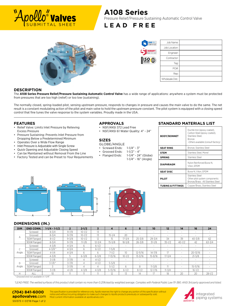
A108 Series Pressure Relief/Pressure Sustaining Automatic Control Valve LEAD FREE S U B M I T TA L S H E E T Job Name: Job Location: Engineer: Contractor: Tag: PO#: Rep: Wholesale Dist.: DESCRIPTION The A108 Series Pressure Relief/Pressure Sustaining Automatic Control Valve has a wide range of applications: anywhere a system must be protected from pressures that are too high (relief) or too low (sustaining). The normally closed, spring-loaded pilot, sensing upstream pressure, responds to changes in pressure and causes the main valve to do the same. The net result is a constant modulating action of the pilot and main valve to hold the upstream pressure constant. The pilot system is equipped with a closing speed control that fine tunes the valve response to the system variables. Proudly made in the USA. FEATURES APPROVALS • Relief Valve: Limits Inlet Pressure by Relieving Excess Pressure • Pressure Sustaining: Prevents Inlet Pressure from Dropping Below a Predetermined Minimum • Operates Over a Wide Flow Range • Inlet Pressure is Adjustable with Single Screw • Quick Opening and Adjustable Closing Speed • Can be Maintained without Removal From the Line • Factory Tested and can be Preset to Your Requirements • NSF/ANSI 372 Lead Free • NSF/ANSI 61 Water Quality: 4” - 24” STANDARD MATERIALS LIST BODY/BONNET Ductile Iron (epoxy coated), Carbon Steel (epoxy coated), Stainless Steel, Bronze -Others available (consult factory) SEAT RING Bronze, Stainless Steel STEM Stainless Steel, Monel SPRING Stainless Steel DIAPHRAGM Nylon Reinforced Buna-N, Viton, EPDM SEAT DISC Buna-N, Viton, EPDM PILOT Stainless Steel Other pilot system components: Bronze/Brass -All Stainless Steel TUBING & FITTINGS Copper/Brass, Stainless Steel SIZES GLOBE/ANGLE • Screwed Ends: • Grooved Ends: • Flanged Ends: 1-1/4” - 3” 1-1/2” - 4” 1-1/4” - 24” (Globe) 1-1/4” - 16” (Angle) DIMENSIONS (IN.) DIM A C Angle D Angle H END CONN. Screwed Grooved 150# Flanged 300# Flanged Screwed Grooved 150# Flanged 300# Flanged Screwed Grooved 150# Flanged 300# Flanged ALL 1-1/4 – 1-1/2 8-3/4 8-3/4 8-1/2 8-3/4 4-3/8 4-3/8 * 4-1/4 4-3/8 3-1/8 3-1/8 * 3 3-1/8 10 2 9-7/8 9-7/8 9-3/8 9-7/8 4-3/4 4-3/4 4-3/4 5 3-7/8 3-7/8 3-7/8 4-1/8 11 2-1/2 10-1/2 10-1/2 10-1/2 11-1/8 6 6 6 6-3/8 4 4 4 4-3/8 11 3 13 13 12 12-3/4 6-1/2 6-1/2 6 6-3/8 4-1/2 4-1/2 4 4-3/8 11 4 15-1/4 15 15-5/8 7-5/8 7-1/2 7-13/16 5-5/8 5-1/2 5-13/16 12 6 20 17-3/4 18-5/8 10 10-1/2 6 6-1/2 13 8 25-3/8 26-3/8 12-11/16 13-3/16 8 8-1/2 14 10 29-3/4 31-1/8 14-7/8 15-9/16 11-3/8 12-1/16 17 12 34 35-1/2 17 17-3/4 11 11-3/4 18 14 39 40-1/2 20 16 40-3/8 42 20-13/16 21-5/8 15-11/16 16-1/2 20 24 62 63-3/4 28-1/2 * Grooved end not available in 1-1/4”. *LEAD FREE: The wetted surfaces of this product shall contain no more than 0.25% lead by weighted average. Complies with Federal Public Law 111-380. ANSI 3rd party approved and listed. (704) 841-6000 apollovalves.com SS1373 © 07/18 Page 1 of 2 This specification is provided for reference only. Apollo reserves the right to change any portion of this specification without notice and without incurring obligation to make such changes to Apollo products previously or subsequently sold. Most current information available at apollovalves.com. A108 Series Pressure Relief/Pressure Sustaining Automatic Control Valve LEAD FREE S U B M I T TA L S H E E T PART NUMBER MATRIX A108 MODEL NUMBER A108 - STANDARD G 002 020 1 1 1 VALVE TYPE/ CONNECTION FULL PORT SERIES EXTENSION VALVE SIZE - BODY & BONNET SEAT RING FULL PORT MATERIAL MATERIAL A - ANGLE/FLANGED ANSI CLASS 150 002 - PRESSURE RELIEF/ PRESSURE SUSTAINING 012 - 1-1/4” 015 - 1-1/2” 1 - DUCTILE IRON NSF 61-EPOXY COATED B - ANGLE/FLANGED ANSI CLASS 300 003 - PRESSURE RELIEF/ PRESSURE SUSTAINING AND CHECK VALVE 020 - 2” 2 - CAST STEEL C - ANGLE/THREADED (1-1/4” – 3”) E - ANGLE/GROOVED ENDS (1-1/2” – 4”) 025 - 2-1/2” 5 - B61 BRONZE 030 - 3” 7 - STAINLESS STEEL 1 - BRONZE B61 2 - STAINLESS STEEL 040 - 4” 004 PRESSURE RELIEF/ PRESSURE SUSTAINING AND SOLENOID SHUTOFF VALVE F - ANGLE/FLANGED CLASS 300 X CLASS 150 G - GLOBE/FLANGED ANSI CLASS 150 (FULL & REDUCED PORT) PILOT, FITTINGS, TUBE 3 ELASTOMERS 1 - PILOT: SS 3 - EPDM FITTINGS: BRASS (STANDARD NSF-61) TUBE: CU 8 - PILOT: SS FITTINGS: SS TUBE: SS 9 - PILOT: BRONZE FITTINGS: SS TUBE: SS 060 - 6” 080 - 8” 010 - 10” 120 - 12” 140 - 14” 160 - 16” 240 - 24” H - GLOBE/FLANGED ANSI CLASS 300 (FULL & REDUCED PORT) J - GLOBE/THREADED ENDS (1-1/4” – 3”) V - GLOBE/GROOVED ENDS (1-1/2” – 4”) HOW TO ORDER YOUR A108 VALVE When Ordering Please Provide: • Fluid to be Controlled • Model Number • Size • Trim Material • Pressure Setting or Spring Range • Special Requirements / Installation Requirements For maximum efficiency, the OCV control valve should be mounted in a piping system so that the valve bonnet (cover) is in the top position. Other positions are acceptable but may not allow the valve to function to its fullest and safest potential. In particular, please consult the factory before installing 8” and larger valves, or any valves with a limit switch, in positions other than described. Space should be taken into consideration when mounting valves and their pilot systems. A routine inspection & maintenance program should be established and conducted yearly by a qualified technician. (704) 841-6000 apollovalves.com SS1373 © 07/18 Page 2 of 2 This specification is provided for reference only. Apollo reserves the right to change any portion of this specification without notice and without incurring obligation to make such changes to Apollo products previously or subsequently sold. Most current information available at apollovalves.com.

