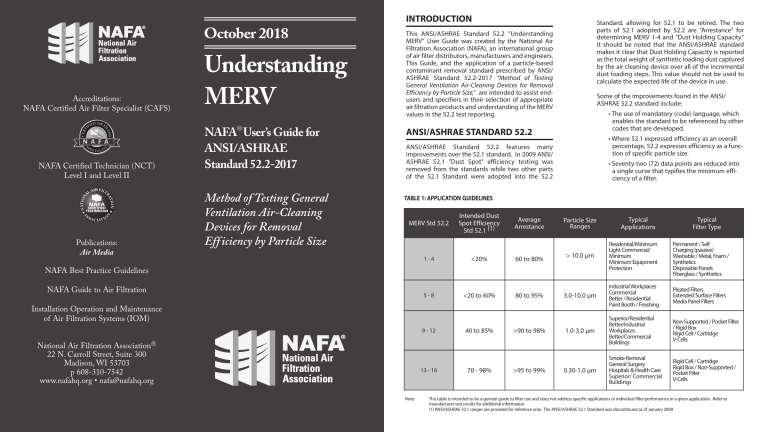
October 2018 Accreditations: NAFA Certified Air Filter Specialist (CAFS) NAFA Certified Technician (NCT) Level I and Level II Publications: Air Media Understanding MERV NAFA User’s Guide for ANSI/ASHRAE Standard 52.2-2017 Method of Testing General Ventilation Air-Cleaning Devices for Removal Eff iciency by Particle Size INTRODUCTION Standard, allowing for 52.1 to be retired. The two parts of 52.1 adopted by 52.2 are "Arrestance" for determining MERV 1-4 and "Dust Holding Capacity." It should be noted that the ANSI/ASHRAE standard makes it clear that Dust Holding Capacity is reported as the total weight of synthetic loading dust captured by the air cleaning device over all of the incremental dust loading steps. This value should not be used to calculate the expected life of the device in use. This ANSI/ASHRAE Standard 52.2 "Understanding MERV" User Guide was created by the National Air Filtration Association (NAFA), an international group of air filter distributors, manufacturers and engineers. This Guide, and the application of a particle-based contaminant removal standard prescribed by ANSI/ ASHRAE Standard 52.2-2017 “Method of Testing General Ventilation Air-Cleaning Devices for Removal Efficiency by Particle Size,” are intended to assist endusers and specifiers in their selection of appropriate air filtration products and understanding of the MERV values in the 52.2 test reporting. Some of the improvements found in the ANSI/ ASHRAE 52.2 standard include: • The use of mandatory (code) language, which enables the standard to be referenced by other codes that are developed. ANSI/ASHRAE STANDARD 52.2 • Where 52.1 expressed efficiency as an overall percentage, 52.2 expresses efficiency as a function of specific particle size. ANSI/ASHRAE Standard 52.2 features many improvements over the 52.1 standard. In 2009 ANSI/ ASHRAE 52.1 "Dust Spot" efficiency testing was removed from the standards while two other parts of the 52.1 Standard were adopted into the 52.2 • Seventy-two (72) data points are reduced into a single curve that typifies the minimum efficiency of a filter. TABLE 1: APPLICATION GUIDELINES MERV Std 52.2 Intended Dust Spot Efficiency Std 52.1 (1) Average Arrestance 1-4 <20% 60 to 80% 5-8 <20 to 60% 80 to 95% Particle Size Ranges Installation Operation and Maintenance of Air Filtration Systems (IOM) 9 - 12 National Air Filtration Association 22 N. Carroll Street, Suite 300 Madison, WI 53703 p 608-310-7542 www.nafahq.org • [email protected] 13 - 16 Note: 40 to 85% 70 - 98% >90 to 98% >95 to 99% Typical Filter Type > 10.0 µm Residential/Minimum Light Commercial/ Minimum Minimum Equipment Protection Permanent / Self Charging (passive) Washable / Metal, Foam / Synthetics Disposable Panels Fiberglass / Synthetics 3.0-10.0 µm Industrial Workplaces Commercial Better / Residential Paint Booth / Finishing Pleated Filters Extended Surface Filters Media Panel Filters 1.0-3.0 µm Superior/Residential Better/Industrial Workplaces Better/Commercial Buildings Non-Supported / Pocket Filter / Rigid Box Rigid Cell / Cartridge V-Cells 0.30-1.0 µm Smoke Removal General Surgery Hospitals & Health Care Superior/ Commercial Buildings Rigid Cell / Cartridge Rigid Box / Non-Supported / Pocket Filter V-Cells NAFA Best Practice Guidelines NAFA Guide to Air Filtration Typical Applications This table is intended to be a general guide to filter use and does not address specific applications or individual filter performance in a given application. Refer to manufacturer test results for additional information. (1) ANSI/ASHRAE 52.1 ranges are provided for reference only. The ANSI/ASHRAE 52.1 Standard was discontinued as of January 2009. STANDARD 52.2 TEST PROCEDURE: HOW DATA IS OBTAINED An air filter’s performance is determined by measuring the particle counts upstream and downstream of the air-cleaning device being tested. Particle counts are taken over the range of particle sizes six times, beginning with a clean filter and then after the addition of standard synthetic ASHRAE dust loadings for five additional measurement cycles. A laboratory aerosol generator, which operates much like a paint sprayer, is used to create a challenge aerosol of known particle size in the air stream. This will generate particles covering the 12 required particle size ranges for the test (see Table 2). The challenge aerosol is injected into the test duct and particle counts are taken for each of the size data points. The filter’s performance, on each of the twelve particle sizes, during the six test cycles (a total of 72 value or calculated value) is determined. For each value or calculated value, the filtration efficiency is stated as a ratio of the downstream-toupstream particle count. The lowest values over the six test cycles are then used to determine the Composite Minimum Efficiency Curve. Using the lowest measured efficiency avoids the misinterpretation of averaging and provides a “worst case” experience over the entire test. The twelve size ranges are placed in three larger groups according to the following schedule: ranges 1-4 (or E1, which is 0.3 to 1.0 µm), ranges 5-8 (or E2, which is 1.0 to 3.0 µm), and ranges 9-12 (or E3, which is 3.0 to 10.0 µm). Averaging the Composite Minimum Efficiency for each of these groups will calculate the average Particle Size Efficiency (PSE), and the resulting three percentages (E1, E2, E3) are then used to determine the MERV. Since the 2012 version, the MERV table has been changed to reduce MERV changes for small changes in E values. For filters that release particles after dust loading, the shedding penalty was removed, and a calculated release rate was added. The test humidity range was reduced to 45% ± 10%, and there are tighter specifications on the particle counters. TABLE 2: ANSI/ASHRAE 52.2 PARTICLE SIZE RANGES Range 1 2 3 4 5 6 7 8 9 10 11 12 Size 0.30 to 0.40 0.40 to 0.55 0.55 to 0.70 0.70 to 1.00 1.00 to 1.30 1.30 to 1.60 1.60 to 2.20 2.20 to 3.00 3.00 to 4.00 4.00 to 5.50 5.50 to 7.00 7.00 to 10.00 Group E1 E2 E3 MINIMUM EFFICIENCY REPORTING VALUE (MERV) An "overall" reporting value of a 52.2-evaluated air filter is the expression of the Minimum Efficiency Reporting Value (MERV). The MERV is a single number that is used, along with the air velocity at which the test was performed, to simplify the extensive data generated by the method of testing. MERV is expressed on a 16 point scale and is derived from the PSE for each of the three groups. (See Table 3: MERV Parameters.) The average PSE for each of the three groups (E1, E2 and E3) is referenced against the Minimum Efficiency Reporting Value Parameters (see Table 3: MERV parameters). Move up the appropriate Range Group (E1, E2 and E3) on Table 3 and record the MERV to the left of the first true statement. Do this for all three groups. STANDARD TEST AIRFLOW RATES APPENDIX J - ADDED IN 2008 The Minimum Efficiency Reporting Value (MERV) must be stated with the air velocity at which the filter was tested. For example, if the filter was tested with an air velocity of 492 FPM and was found to be MERV 8, the filter’s Minimum Efficiency Reporting Value would be MERV 8 @ 492 FPM. ASHRAE Standard 52.2 tests are to be conducted at one of seven airflow rates: Much research, including two ASHRAE research projects, have revealed a potential loss in efficiency in some filters (charged media) as they are used. Normative approved Appendix J has been added as an optional conditioning step to the 52.2 Standard to provide a method of identification of the drop in filter efficiency. The reported value per Appendix J would be referred to as MERV A. Thus filters tested per Standard 52.2 with Appendix J option would have a MERV and a MERV A reported value. 118 FPM (0.60 m/s) 246 FPM (1.25 m/s) 295 FPM (1.50 m/s) 374 FPM (1.90 m/s) 492 FPM (2.50 m/s) 630 FPM (3.20 m/s) 748 FPM (3.80 m/s) MINIMUM FINAL RESISTANCE The minimum final resistance shall be twice the initial resistance, or as specified. The choice of final pressure drop will change the dust holding capacity and possibly the arrestance such that care should be taken in comparing values. Designated final resistance values have been removed as several products have been designed with efficiencies for markets that will not support the higher pressure drops previously required. AVERAGE ARRESTANCE AND DUST HOLDING CAPACITY (DHC) Arrestance and DHC values will be reported on all filters tested per 52.2 testing procedures and is the only value reported for MERV values 1 through 4. CONCLUSION Contact your local National Air Filtration Association (NAFA) member company. Most NAFA members are staffed by NAFA Certified Air Filter Specialists (CAFS) to assist in the proper selection of filters for your application. TABLE 3: MERV PARAMETERS Standard 52.2 Minimum Efficiency Reporting Value (MERV) Composite Average Particle Size Efficiency, % in Size Range, µm Average Arrestance, % Range 1 (0.3-1.0) Range 2 (1.0-3.0) Range 3 (3.0-10.0) 1 n/a n/a E3 < 20 Aavg < 65 2 n/a n/a E3 < 20 65 ≤ Aavg < 70 3 n/a n/a E3 < 20 70 ≤ Aavg < 75 4 n/a n/a E3 < 20 75 ≤ Aavg 5 n/a n/a 20 ≤ E3 n/a 6 n/a n/a 35 ≤ E3 n/a 7 n/a n/a 50 ≤ E3 n/a 8 n/a 20 ≤ E2 70 ≤ E3 n/a 9 n/a 35 ≤ E2 75 ≤ E3 n/a 10 n/a 50 ≤ E2 80 ≤ E3 n/a 11 20 ≤ E1 65 ≤ E2 85 ≤ E3 n/a 12 35 ≤ E1 80 ≤ E2 90 ≤ E3 n/a 13 50 ≤ E1 85 ≤ E2 90 ≤ E3 n/a 14 75 ≤ E1 90 ≤ E2 95 ≤ E3 n/a 15 85 ≤ E1 95 ≤ E1 90 ≤ E2 95 ≤ E2 95 ≤ E3 n/a 95 ≤ E3 n/a 16
