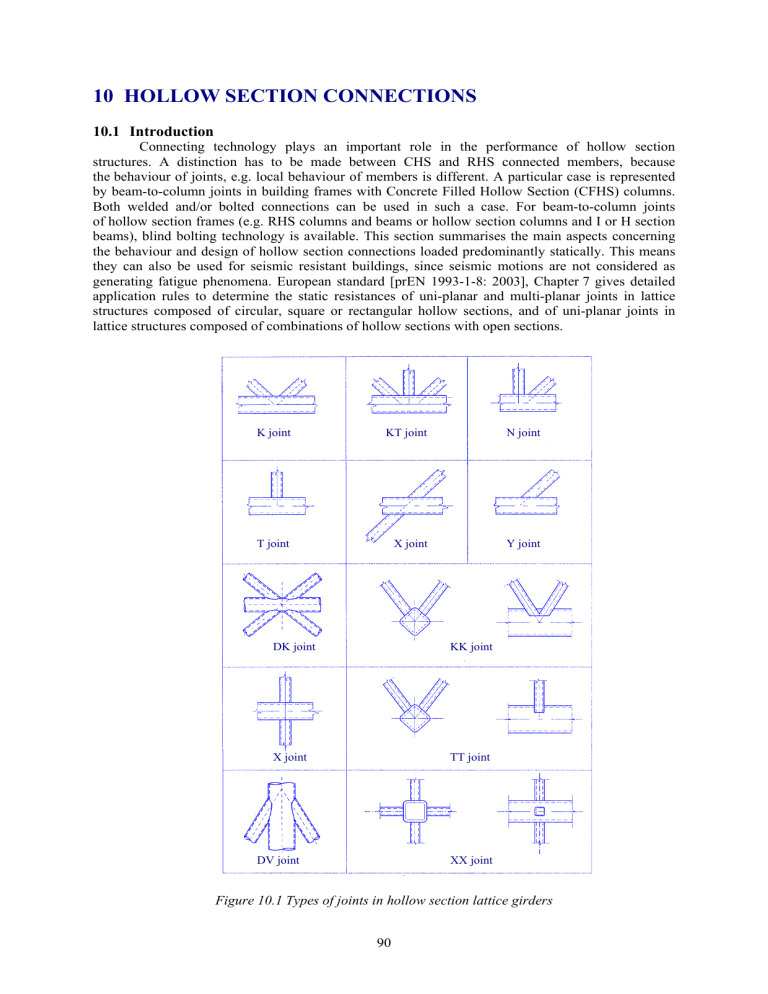
10 HOLLOW SECTION CONNECTIONS 10.1 Introduction Connecting technology plays an important role in the performance of hollow section structures. A distinction has to be made between CHS and RHS connected members, because the behaviour of joints, e.g. local behaviour of members is different. A particular case is represented by beam-to-column joints in building frames with Concrete Filled Hollow Section (CFHS) columns. Both welded and/or bolted connections can be used in such a case. For beam-to-column joints of hollow section frames (e.g. RHS columns and beams or hollow section columns and I or H section beams), blind bolting technology is available. This section summarises the main aspects concerning the behaviour and design of hollow section connections loaded predominantly statically. This means they can also be used for seismic resistant buildings, since seismic motions are not considered as generating fatigue phenomena. European standard [prEN 1993-1-8: 2003], Chapter 7 gives detailed application rules to determine the static resistances of uni-planar and multi-planar joints in lattice structures composed of circular, square or rectangular hollow sections, and of uni-planar joints in lattice structures composed of combinations of hollow sections with open sections. K joint KT joint N joint T joint X joint Y joint DK joint KK joint X joint TT joint DV joint XX joint Figure 10.1 Types of joints in hollow section lattice girders 90 The static resistances of the joints are expressed in terms of maximum design axial and/or moment resistances for the brace members. The application rules are valid both for hot finished hollow sections to EN 10210 and for cold formed hollow sections to EN 10219, if the dimensions of the structural hollow sections fulfil the necessary requirements. The nominal wall thickness of hollow sections should be limited to a minimum of 2,5 mm and should not be greater than 25 mm unless special measures have been taken to ensure that the through thickness properties of the material is adequate. The types of joints covered by standard prEN 1993-1-8 are indicated in Figure 10.1. The application rules given in paragraph 7.1.2 of prEN 1993-1-8 may be used only where all the given conditions are satisfied. 10.2 Welded connections Even if bolted connections to hollow sections are utilised to assemble prefabricated elements or space structures, the most used method to assemble CHS members is welding, especially for trusses. According to prEN 1993-1-8, the design joint resistances of connections between hollow sections and of connections of hollow sections to open sections, should be based on the following failure modes as applicable: • Chord face failure (plastic failure of the chord face) or chord plastification (plastic failure of the chord cross-section); • Chord side wall failure (or chord web failure) by yielding, crushing or instability (crippling or buckling of the chord side wall or chord web) under the compression brace member; • Chord shear failure; • Punching shear failure of a hollow section chord wall (crack initiation leading to rupture of the brace members from the chord member); • Brace failure with reduced effective width (cracking in the welds or in the brace members); • Local buckling failure of a brace member or of a hollow section chord member at the joint location. 10.3 Bolted connections Connecting two hollow section members or a hollow section and an open profile or a plate directly to each other by bolting can be difficult unless the joint is located close to the open end of a hollow section member. Otherwise it is necessary to take measures, such as cutting a hand access hole in the structural hollow section member to enable the bolt to be tightened from the inside or using “through” or “blind” bolts. The reason for this special situation is evident, as the hollow section allows free access only to the outside; any access to the inside is restricted. Bolted connections remain nonetheless desirable in many cases in spite of the unique condition of non-accessibility to the inside of a hollow section. However, in these cases, the hollow sections can be joined indirectly using flange or capping plates, which makes it possible to effect such bolted connections in a simple and economical manner. The main methods of assembly by bolting are described bellow. Bolted connections are mostly detachable. They are selected for the on site assembly in order to avoid site welding, which may cause welding errors due to environmental difficulties. Site welding is also more costly than site bolting. This paragraph is presented in accordance with “Design guide for structural hollow sections in mechanical applications” of J. Wardenier et al, see [CIDECT, 1995] and “Guide on the use of bolts: single sided blind bolting systems of N. F. Yeomans [Yeomans, 2002]. The main types of bolted connections for hollow section structures are: Bolted knee joints, Flange connections, Splice joints, Joints with fork ends, Screwed tensioner, Through bolting, Bolted connections with flattened ends, Hinged support, Column bases, Fish plate connections, Bolted subassemblies, and Fixing bolts through hand access holes [CIDECT, 1995; Elremaily, Azizinamini, 2001b; Elremaily, Azizinamini, 2001a]. These connections are realised using intermediate connecting steel devices, which are welded on the hollow section members, the bolted connections themselves being designed as normal connections according to prEN 1993-1-8, Chapter 3 [prEN 1993-1-8: 2003]. For this reason, design of hollow section connections does not imply specific requirements. 91 10.4 Design considerations A structure made of hollow sections and loaded by predominantly static loading should be designed in such a way that it has a ductile behaviour. This means that the critical members or joints should provide sufficient rotation capacity. In this case, secondary bending moments due to imposed deformations or due to the joint stiffness may be neglected in design. Where the critical member or connection do not provide sufficient rotation capacity, as in case of thin walled sections, a second order elastic analysis should be used. Design of hollow section connections should be done in accordance with prEN 1993-1-8 [prEN 1993-1-8: 2003], Chapter 7: Hollow section joints and CIDECT Design guide for structural hollow sections in mechanical applications, Chapter 5: Design considerations for connections [CIDECT, 1995], [Kato, 1988]. Connection detailing for both welded and bolted connections is given in CIDECT Design guide for structural hollow sections in mechanical applications, Chapter 6: Connection detailing [CIDECT, 1995]. Q&A 10.1 Circular Hollow Section Joints What analytical models are used for calculating the resistance of CHS joints? ___________________________________________________________________________ The following three models are currently used: • Tube model for chord face failure • Model for punching shear failure • Model for chord shear failure Tube model for chord face failure The joint is modelled by a tube of effective length Be, having a geometry and mechanical characteristics identical with the CHS (Circular Hollow Section Joints) chord as presented in Figure 10.2. Figure 10.2 Tube model for a X joint of CHS Neglecting axial and shear forces, and taking into account the effective length Be, which is determined by tests, the effort corresponding to the plastification of the tube should be: N1 y = t2 C0 ⋅ f yo ⋅ o , sinθ1 1 − C1 β (10.1) 92 where C0, C1 are constants, θ1 is the angle between the diagonal and the chord and β = d1/d0 is the ratio of diameters of the tubes [CIDECT, 1991]. This model gives good results for T, Y and X joints. For more complex joints such as K and N, other parameters like distance between diagonals and axial forces should be taken into account. Model for punching shear failure This model is presented in Figure 10.3 for a Y joint subject to tension. The effort in the diagonal is obtained by the formula: N2 = f yo 3 π d 2 to 1 + θ2 2 sin 2 θ 2 (10.2) This criterion is generally true only for reduced values of β, where β = d2/d0, because if β increases, the load will be transferred to the chord by circular stresses. Design rules based on the model for punching shear failure are largely used in offshore design. Figure 10.3 Model for punching shear failure of the chord in a CHS joint Model for chord shear failure As seen in Figure 10.4, for K and N joints with a gap between diagonals, the chord crosssection may collapse in the gap section, because of the combination of axial force, shear force and bending moment. gap V Figure 10.4 Model for chord shear failure in a CHS joint 93 If the chord is a compact section, plastic design gives the following relations: f yo (d o − t o ) t o , N i sin θ i ≤ 2 3 N o ,gap ≤ π (d o − to ) to f yo , M o ,gap ≤ (d o − to ) to f yo . 2 (10.3) (10.4) (10.5) Generally, the bending moments are quite small and only the interaction between the axial force and the shear force has to be considered 2 N o ,gap N i sin θ i ≤ 1,0 . + (10.6) π (d − t ) t f 2 f yo o o o yo (d o − to ) to 3 If the gap is small, the diagonals stiffen the chord, which considerably increases the shear resistance. 2 Q&A 10.2 Rectangular Hollow Section Joints What analytical models are used for calculating the resistance of RHS joints? ___________________________________________________________________________ Analytical models are used to describe the behaviour of connections and to study the effect of the principal parameters. Taking into account all the parameters is difficult and too complicated. For these reasons, different simplified models are used. In combination with test results made in laboratories, these models have been used to establish the design equations. Y joint Model Figure 10.5 Plastic lines model for joints of type T, Y or X (chord face failure) 94 Plastic line model The general principle of the model, illustrated in Figure 10.5, for an Y RHS joint, consists of equalising the work of the force N1 with a δ displacement, with the internal work in the plastic hinges (length li and rotation angle ψi. If θi, is the angle between the brace and the chord, the capacity of the members [APK, 1996] obtained form the following expression f t 2 h1 1 + 4 1 − β N 1 = yo o . (10.7) 1 − β bo sin θ1 sin θ1 Model for brace punching shear failure This model is presented in Figure 10.6 for a Y joint subject to tension. The shear resistance for T, Y and X joints is obtained by the formula f 2 h1 1 + 2 bep . (10.8) N 1 = yo to 3 sin θ1 sin θ1 a) longitudinal section b) cross section c) plane section Figure 10.6 Plastic lines model for joints of type T, Y or X (chord face failure) Model of the brace effective width The resistance is calculated as a function of the brace dimensions, which for T, Y and X joints is N 1 = f y 1 ⋅ t1 ⋅ (2 h1 − 4 t1 + 2 beff ) . (10.9) Model of chord shear failure The shear resistance of the chord may be calculated analytically using the plastic design of the section: A v f yo V pl = , (10.10) 3 where Av = (2 h0+α b0) t0 and α is a function of g/t0. The rest of the chord section is taking the axial effort. Using the von Mises criterion of plasticity, the following interaction formula is obtained: 95 2 V N o ,gap ,Sd ≤ ( Ao − Av ) f yo + Av f yo 1 − Sd , (10.11) V pl ,Rd where VSd is the design shear effort and Vpl,Rd is the plastic resistance to the shear effort of a section calculated with relation (10.10), divided by the safety partial factor γM0. Figure 10.7 Model for RHS chord shear in the gap of K or N joint Model for the plastification or the local buckling of the lateral chord side walls T, Y and X joints, with a high level of β, may reach failure by the plastification or the local buckling of the lateral chord side walls. For RHS joints of the same width, the model presented in Figure 10.8 gives h 1 . N 1 = 2 f yo t o 1 + 5 t o sin θ 1 sin θ 1 (10.12) Figure 10.8 Model for the plastification or the local buckling of the lateral chord side walls Q&A 10.3 Joints between Hollow and Open Section Members What analytical models are used for connections between CHS or RHS members and I or H section chords? ___________________________________________________________________________ The design resistance is calculated using simplified models which have been verified experimentally. 96 Model of the brace effective width For joints made by hollow sections welded on I or H sections, there is an unequal distribution of the stresses and deformations at the end of a hollow member, due to the web and the different rigidity between the ends and the central part of the flange, see Figure 10.9. If the load is increasing, this phenomena is more important and may reach a premature failure of the joint, by the collapse between the member in tension and the chord flange, or by local buckling at the edge of the member in tension. To cover this risk of collapse, the term of transversal cracking is used commonly and the majority of authors have introduced the effective width. This term is representative for the perimeter of the hollow section, able to transmit the effort at the stage of the collapse, see Figure 10.10 [APK, 1996]. Figure 10.9 Distribution of the stresses and deformations at the end of a RHS member Figure 10.10 Notion of effective perimeter The ultimate resistance of the member for T, Y, X, K and N (with gap) joints may be computed as follow: N iRd = 2 f yi ti beff , (10.13) where beff being equal with the half length of the effective part of the perimeter of the hollow member. The following formula may be used to compute beff: beff = tw + 2 r + 7 f yo f yi tf (10.14) Model of chord shear failure The risk of failure by shear of the chord is the most probably failure mode for K and N connections with gap Figure 10.11. The shear resistance of the chord could be computed using the following formula, where Av represents the effective shear area: 97 V pl = Av f yo (10.15) 3 Figure 10.11 Shear of the chord in a K joint with gap Model of the local plastification of the chord web The approach of calculating the local plastification of the chord web in tension and the local crushing of the chord web is similar to that used to determine the local tension capacity of the web of the I and H section. The method is shown in Figure 10.12 and the resistance Ni,Rd is given by the following expression f t b (10.16) N iRd = yo w w . sinθ i Figure 10.12 Local plastification of the chord web Q&A 10.4 Design Charts What is the background to the design charts? __________________________________________________________________________ The design charts shown in Figure 10.13 are based on the efficiency coefficient Ce of the brace [APK, 1996]. The efficiency coefficient is obtained by the following formula 98 f t kp N1.Rd = Ce yo o . (10.17) A1 f y 1 f y 1 t1 sinθ1 Efficiency parameter Ce (CT for T and Y joints, CX for X joints and CK for K and N joints) means the efficiency of a joint with kp = 1,0 and t1 = 90, with identical thickness and steel grade in braces and chord. C e 1,0 d0 0,9 t0 f yo t o k p N 1.Rd = CT f y 1 t 1 sin θ 1 A1 f y 1 θ1 0,8 10 0,7 0,6 15 0,5 20 0,4 30 40 50 0,3 0,2 0,1 0,0 0,0 0,1 0,2 0,3 0,4 0,5 0,6 0,7 0,8 0,9 1,0 β Figure 10.13 Design chart for T and Y joints of CHS sections In practise, it is important to evaluate quickly the joint resistance of RHS sections, which may be made by design charts given for K, N, T, Y and X joints. These charts are based on the EN 1993-1-8 recommendations. The joint resistance is given by an efficiency coefficient Ce. Generally, the efficiency is given by the following formula [APK, 1996]: f yo t o k n N 1 Rd = Ce (10.18) Ai f yi f yi t i sin θ i For instance, Figure 10.14 presents the efficiency of a K gap joint, of RHS. For joints with no gap, the total efficiency is given in the chart from Figure 10.15. The reference [CIDECT, 1995] contains design charts related to all the types of RHS joints with gap or overlapped. 99 C Kg 1,0 0,9 f y0 t 0 k n N 1 .Rd = C Kg Ai f yi f yi t i sin θ i 0,8 0,7 b 1+ b 2 0,6 2 bi 0,5 1,6 1,4 1,2 1,0 0,8 0,6 0,4 0,3 0,2 0,1 b0 0,0 10 15 20 25 30 35 t0 Figure 10.14 Chart of efficiency of braces for welded K and N RHS joints with gap N i 1,0 Ai f yi 0,9 2,0 1,75 1,5 1,25 1,0 0,8 0,7 0,6 f yj t j f yi t i 0,5 0,4 0,3 0,2 0,1 bj 0,0 10 15 20 25 30 35 tj Figure 10.15 Chart of efficiency of braces for welded K and N RHS joints with no gap Q&A 10.5 Blind Bolting What different types of blind bolts are available? ___________________________________________________________________________ Flowdrill Drill System The Flowdrill system is a method for the extrusion of holes using a four lobed tungstencarbide friction drill [Yeomans, 2002]. The process is shown schematically in Figure 10.16. A typical beam end plate connection is described in Figure 10.17. The results of a series of tests on individual flow-drilled holes and on connections made using the Flowdrill system have shown that they are suitable for structural applications [Korol et al, 1993] and [Ballerini et al, 1996]. These tests have shown that: • holes can be produced in sections from 5,0 to 12,5 mm thick, [Barnett et al, 2001], 100 • threaded roll tapped holes with M16, M20 and M24 ISO course thread profiles can be made. If the threads are made using a standard cutting tap the pull-out capacities will be lower than those shown in Table 10.1, • the full tension capacity of grade 8.8 bolts can be carried by flow-drilled and roll tapped holes, provided that the material thickness is equal to or greater than the minimum thickness shown in Table 10.1 and the material has a nominal yield strength in the range 275 to 355 MPa, • the shear and bearing capacities of the hole and bolt can be calculated in the normal manner. Figure 10.16 Schematic of the Flowdrill process Figure 10.17 Beam/column connection Table 10.1 Minimum material thickness for full grade 8.8 bolt tension capacity Bolt size and grade M16 grade 8.8 M20 grade 8.8 M24 grade 8.8 Minimum material thickness, mm 6.4 8.0 9.6 Lindapter HolloBolt Insert The HolloBolt is a three part pre-assembled unit consisting of a main body, a threaded truncated cone and a standard grade 8.8 bolt and is shown in Figure 10.18a, a five-parts system is also available [Yeomans, 2002]. Figure 10.18 a) Insert (as supplied), b) beam/column connection Huck Ultra-Twist Bolt The Ultra-Twist bolt is a pre-assembled unit [Yeomans, 2002]. An exploded view of the bolt is shown in Figure 10.19a. The Ultra-Twist bolt is installed using an electric bolting wrench in holes 2 mm larger than the outside diameter of the bolts, which provides conventional clearances for fit-up, Figure 10.19b. 101 Figure 10.19 Huck Ultra-Twist bolt, a) exploded view of the bolt, b) installation procedure Stud Welding Threaded studs welded to steel columns can also be used to produce connections. A typical beam end plate connection, without counter sunk holes is shown in Figure 10.20 [Maquoi et al, 1984]. 102 Welded nuts There are several other methods available for making bolted connections, which can be fixed from one side only [Sadri, 1994]. Two of these are briefly described below. The first method is simply drilling and tapping the steel section, but this generally needs a wall thickness of 16 mm or more to generate enough pull out capacity. Another method [Kato, 1988], is to drill holes in the steel section large enough for a nut of the required size to be inserted and then to weld the nut to the steel section flush with the outside surface, see Figure 10.21. Figure 10.20 Welded threaded stud connection Figure 10.21 Nuts welded into hollow section wall Q&A 10.6 Hollow Section Joints using High Strength Steel Can the rules given in prEN 1993-1-8 be applied to high strength steels? ___________________________________________________________________________ The rules given in prEN 1993-1-8 may be applied to high strength steels. Clause 7.1.1 (4) specifies that nominal yield strength of hot finished hollow sections and the nominal yield strength of the basic material of cold formed hollow sections should not exceed 460 MPa. For grades S 420 and S 460 the static resistances given in this section should be reduced by a factor 0,9. According to EN 10210 and EN 10219 the requirements for material is determined based on the end product, not on the base material. CIDECT Design Guide [CIDECT, 1995] stipulates that it is possible for structural hollow sections in special steels to be produced, e.g. very high strength steels with yield strengths up to 640 MPa or higher, weathering steels and steels with improved or special chemical compositions, etc.; often large quantities would require to be ordered [Oyj, Vainio, 2000]. Q&A 10.7 Offshore Construction Can the recommendations in prEN 1993-1-8 be applied to the large sections used in offshore construction? ___________________________________________________________________________ The field of application of hollow sections in engineering is large and their specific domains of application are listed in [CIDECT, 1995] including offshore structure. The design rules of prEN 1993-1-8: 2003, Chapter 7 could be used in the case of offshore structures, provided the general conditions are fulfilled. In the case of offshore structures these limits of applications are mostly not fulfilled and special requirements must be used. In addition fatigue design conditions need to be considered. 103
