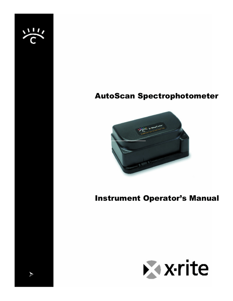
AutoScan Spectrophotometer Instrument Operator’s Manual Electronic Emission Notices Federal Communications Commission Notice NOTE: This equipment has been tested and found to comply with the limits for a Class A digital device, pursuant to part 15 of the FCC rules. These limits are designed to provide reasonable protection against harmful interference in a residential installation. This equipment generates, uses and can radiate radio frequency energy and, if not installed and used in accordance with the instructions, may cause harmful interference to radio communications. However, there is no guarantee that interference will not occur in a particular installation. If this equipment does cause harmful interference to radio or television reception, which can be determined by turning the equipment off and on, the user is encouraged to try to correct the interference by one or more of the following measures: Reorient or relocate the receiving antenna. Increase the separation between the equipment and receiver. Connect the equipment into an outlet on a circuit different from that to which the receiver is connected. Consult the dealer or service representative for help. Industry Canada Compliance Statement This digital apparatus does not exceed the Class A limits for radio noise emissions from digital apparatus as set out in the interferencecausing equipment standard entitled: “Digital Apparatus”, ICES-003 of Industry Canada. Avis de conformité aux normes d’Indstrie Canada Cet appareil numérique respecte les limites de bruits radioélectriques applicables aux appareils numériques de Classe A prescrites dans la norme sur le matériel brouilleur : “Appareils numériques”, NMB-003 édictée par Industrie Canada. NOTE: Shielded interface cables must be used in order to maintain compliance with the desired FCC and European emission requirements. For 115V~/230V~: Use only SE30-77 AC Adapter. Für 115V~/230V~: verwenden Sie nur das X-Rite Netzteil P/N SE30-77. Para 115V~/230~: Use solamente el adaptador C.A. de X-Rite, pieza SE30-77. Pour 115V~/230~: Utiliser seulement l’adaptateur AC de X-Rite P/N SE30-77. Per 115V~/230~: Usare solamente il adattatore C.A. al X-Rite, pezzo SE30-77. The Manufacturer: X-Rite, Incorporated Der Hersteller: El fabricante: Le fabricant: Il fabbricante: 4300 44th Street, S.E. Grand Rapids, Michigan 49512 Declares that: gibt bekannt: advierte que: avertit que: avverte che: Spectrophotometer DTP41 is not intended to be connected to a public telecommunications network. an ein öffentliches Telekommunikations-Netzwerk nicht angeschlossen werden soll. no debe ser conectado a redes de telecomunicaciones públicas. ne doit pas être relié à un réseau de télécommunications publique. non deve essere connettuto a reti di telecomunicazioni pubblici. CE Declaration Manufacturer's Name: Manufacturer's Address: X-Rite, Incorporated 4300 44th Street, S.E. Grand Rapids, Michigan 49512 U.S.A. Model Name: Model No.: Spectrophotometer DTP41 Series Directive(s) Conformance: EMC 89/336/EEC LVD 73/23/EEC WEEE As of August 13, 2005, X-Rite products meet the European Union – Waste Electrical and Electronic Equipment (WEEE) directive. Please refer to www.xrite.com for more information on X-Rite’s compliance with the WEEE directive. Table of Contents 1 Overview and Setup ...............................................................................................................................1 Instrument Description ..............................................................................................................................1 Unpacking and Inspection.........................................................................................................................1 Packaging Content ............................................................................................................................................. 1 Instrument Interface ..................................................................................................................................2 USB Driver Installation (Windows Only) ............................................................................................................ 2 Instrument LED Indicator ..........................................................................................................................3 Operation Mode (Green Light) ........................................................................................................................... 3 Calibration Mode (Yellow Light) ......................................................................................................................... 3 Error/Reset Mode (Red Light) ............................................................................................................................ 3 2 3 Changing the Position of the Backing Block .............................................................................................3 Calibration and Measurement ............................................................................................................4 Frequency of Calibration...........................................................................................................................4 Reflection Mode Calibration......................................................................................................................4 Transmission Mode (Black) Calibration ....................................................................................................4 Strip Positioning and Measurement Techniques ......................................................................................5 General Maintenance ...................................................................................................................................6 Repair Information ....................................................................................................................................6 Cleaning the Instrument............................................................................................................................6 General Cleaning ............................................................................................................................................... 6 Cleaning the Strip Reading Mechanism............................................................................................................. 6 4 Cleaning the Reference Strip....................................................................................................................7 Appendices................................................................................................................................................8 Technical Support .....................................................................................................................................8 Instrument Specifications..........................................................................................................................8 Proprietary Notice The information contained in this manual is derived from patent and proprietary data of X-Rite, Incorporated. Publication of this information does not imply any rights to reproduce or use this manual for purposes other than installing, operating, or maintaining this instrument and software. No part of this manual may be reproduced, transcribed, transmitted, stored in a retrieval system, or translated into any language or computer language, in any form or by any means, electronic, magnetic, mechanical, optical, manual, or otherwise, without the prior written permission of an officer of X-Rite, Incorporated. These provisions are intended to state all of the rights and responsibilities between X-Rite, Incorporated and the customer. They supersede all warranties, expressed or implied, and whether of merchantability, fitness or otherwise. The remedies contained in this manual are exclusive. Customer and X-Rite, Incorporated waive all other remedies, including but not limited to consequential damages. This instrument may be covered by one or more patents. Refer to the instrument for actual patent numbers. Copyright © 2007 by X-Rite, Incorporated “ALL RIGHTS RESERVED” X-Rite, X-RiteColor, and the X-Rite Color Logo are registered trademarks of X-Rite, Incorporated. Windows is a registered trademark of Microsoft Corporation. Power Mac is a trademark of Apple Computer, Inc., registered in the United States and other countries. All other logos, brand names, and product names are the properties of their respective holders. Warranty Information X-Rite, Incorporated (“X-Rite”) warrants each instrument manufactured to be free of defects in material and workmanship (excluding battery pack) for a period of 12 months. This warranty shall be fulfilled by the repair or replacement, at the option of X-Rite, of any part or parts, free of charge including labor, F.O.B. its factory or authorized service center. This warranty shall be voided by any repair, alteration, or modification, by persons other than employees of X-Rite, or those expressly authorized by X-Rite to perform repairs, and by any abuse, misuse, or neglect of the product, or by use not in accordance with XRite’s published instructions. X-Rite reserves the right to make changes in design and /or improvements to its products without any obligation to include these changes in any products previously manufactured. Correction of defects by repair or replacement shall constitute fulfillment of all warranty obligations on the part of X-Rite. THIS WARRANTY IS EXPLICITLY IN LIEU OF ANY OTHER EXPRESSED OR IMPLIED WARRANTIES, INCLUDING ANY IMPLIED WARRANTY OF MERCHANTABILITY OR FITNESS FOR ANY PARTICULAR PURPOSE. THIS WARRANTY OBLIGATION IS LIMITED TO REPAIR OR REPLACEMENT OF THE UNIT RETURNED TO X-RITE OR AN AUTHORIZED SERVICE CENTER FOR THAT PURPOSE. This agreement shall be interpreted in accordance with the laws of the State of Michigan and jurisdiction and venue shall lie with the courts of Michigan as selected by X-Rite, Incorporated. 1 Overview and Setup INSTRUMENT DESCRIPTION The X-RiteColor® AutoScan Spectrophotometer is a 24-band color measurement instrument that reports densitometric, colorimetric, and spectral data. The instrument is primarily interfaced with Raster Image Processors (RIPs), Color Copiers, and Color Printers and Proofers utilizing third party color management software control. The instrument is open ended on the left side to read linear groups of patches on large media sheets without cutting. Your instrument package includes separate software utilities for Macintosh and Windows operating systems, and a calibration reference for quick calibration of the instrument. This manual covers the installation, calibration, and maintenance of the X-RiteColor AutoScan Spectrophotometer. Specific instructions for using the instrument with your third-party software program can be found in the third-party software documentation. Instrument Button (Start/Cancel/Calibrate) Three Color LED Indicator Alignment Mark Shipping Spacer (remove) Interface Cable Connection Strip Entrance UNPACKING AND INSPECTION After removing the instrument from the shipping carton, inspect it for damage. If any damage has occurred during shipping, immediately contact the transportation company. Do not proceed with installation until the carrier’s agent has inspected the damage. Your instrument was packaged in a specially designed carton to assure against damage. If shipment is necessary, the instrument should be packaged in the original carton. If the original carton is not available, contact X-Rite to have a replacement shipped to you. Packaging Content Your instrument packaging should contain all the items listed below. If any of these items are missing, contact X-Rite or an Authorized Representative. • DTP41 Instrument • Interface Cable • Power Supply • Calibration Reference • Certificate of Calibration • Documentation, Utility CD and Registration Materials NOTE: DEPENDING ON THE CONFIGURATION, YOUR INSTRUMENT MAY NOT BE AVAILABLE WITH ALL THE OPTIONS SHOWN. 1 X-RiteColor AutoScan Spectrophotometer INSTRUMENT INTERFACE The instrument must be interfaced directly with one of the computer’s Serial or USB ports. For attachment to a Mac MiniDIN 8 Serial Port, you need to use the optional adapter (P/N SE108-DB9PA-01). 1. Quit all programs and shut down the computer before installing interface cabling. 2. Connect appropriate interface cables as shown. CAUTION: Use only the Switching Power Supply (SE30-77) to power the instrument. 3. Plug the small end of the switching power supply into the power input connector of the interface cable. 4. Plug the detachable line cord into the power supply and then into the AC wall receptacle. The instrument does not have an ON/OFF switch. SE30-77 Switching Power Supply Detachable Line Cord AC Wall Receptacle Power Input Locking Connector Operation Grasp and push the connector at this location to insert. SE108-96-02 * Interface Cable Grasp and pull the connector at this location to remove. USB SE108-97-02 * Interface Cable PC DB9 SE108-USBSERDB9 (Optional) SE108-DB9PA-01 (Optional) USB MAC Mini-DIN 8 USB Driver Installation (Windows Only) A USB driver must be installed in the computer to allow the instrument to work with your software application if the USB interface cable is used. Follow the steps below to install the required USB driver. 1. Make sure the switching power supply is plugged into the instrument and the computer in on. 2. After the USB cable is plugged into your computer, you must install the USB driver that came with your instrument. 3. The USB driver is located in the Driver folder on the Manuals and Utilities CD. * May not be included in all models. 2 Overview and Setup INSTRUMENT LED INDICATOR The LED indicates a variety of instrument operation conditions, such as calibration mode, and operation. Below is a complete list of all conditions reported by the LED. Operation Mode (Green Light) • Solid Green Light—self test passed and instrument is ready for use with defined strip. • Slow Flashing Green Light—strip reading in progress (strip being read). • Fast Flashing Green Light—strip reading attempted but the wrong strip was inserted, or strip skewed during reading. Calibration Mode (Yellow Light) • Solid Yellow Light—instrument calibration was entered, ready to start calibration with next button press. • Slow Flashing Yellow Light—instrument calibration in progress (strip being read). • Solid Green Light after Yellow Light—instrument calibration was successful and instrument is ready for use. • Fast Flashing Yellow Light—instrument calibration failed, re-read calibration strip. If error persists, clean instrument and calibration strip (see Section Three). If error still persists, contact your Service Representative. Error/Reset Mode (Red Light) • Solid Red Light—and error was detected, the self test failed. Verify correct power supply is used. Turn power off, reapply power and see if condition is corrected; if not, contact Service Representative. • Solid Green or Yellow changing to Red—an instrument reset is in progress. To initiate a reset, press and hold the button, the LED changes from Green or Yellow to Red. While the LED is Red, press button again (within 10 seconds). The LED changes to Green and the reset is performed, reinstating the factory defaults. If the second button press is not performed when the LED is Red, the instrument will time-out, causing the LED to change to Green and the reset to be aborted. CHANGING THE POSITION OF THE BACKING BLOCK NOTE: Instruments that utilize a “raised white backing block” cannot be repositioned. The backing surface used when measuring paper strips can be alternated between ANSI Black and White Diffusing Opal. The Backing Block is located on the bottom of the Base Assembly. Simply slide the block to the “right” for Black or to the “left” for White (see below). The factory setting for reflection instruments is Black backing. For transmission instruments (DTP41/T), the optics block must remain in the “T/W” position (left) to measure film strips. The block can be slid to the “BL” position (right) for measuring paper strips with a black backing if desired. Reflection Instrument Slide block to the left for White Diffusing Opal backing “BL” is visible with Black Slide block to the right for ANSI Black backing “T/W” is visible with White Opal Transmission Instrument Reflection Only Slot for sliding block to the right (ANSI Black backing) Slot for sliding block to the left (default position) The optics block must be slid to the “T/W” position (transmission) when measuring film strips. A small screwdriver can be used to slide the optics block from one position to the other. 3 2 Calibration and Measurement FREQUENCY OF CALIBRATION Typically, the host computer prompts for an instrument calibration when required. The frequency at which this occurs depends on the application. If desired, a reflection calibration can be invoked manually by pressing the Instrument button—refer below for procedure. At a minimum the instrument should be calibrated once a day for best accuracy. REFLECTION MODE CALIBRATION The X-RiteColor AutoScan Spectrophotometer has a unique automatic calibration feature. When the instrument performs a calibration procedure, the Color Reflection Reference is automatically scanned, simplifying the procedure. The instrument employs a number of self-checking procedures to verify calibration accuracy during normal use. When internal limits are exceeded, the computer calls for a calibration. CALIBRATION NOTE: Handle Color Reflection Reference by the edges. Make sure that the Color Reflection Reference is free of dust, dirt, and smudgemarks. Refer to Section Three for cleaning procedure. Always store the Color Reflection Reference in its protective envelope away from light and heat. 1. Center the designated end of the Color Reflection Reference under the alignment mark. Slowly insert strip past the front idler rollers up to the black bar on the reference strip. 2. To manually force the instrument into calibration mode, press and hold the Instrument button for a minimum of three seconds. The indicator light changes to yellow. Note, if calibration is not performed after a short period of time, the instrument returns to the measurement mode (green light). 3. Press the Instrument button again. The light slowly flashes yellow. After a few moments, the light changes to green and then back to slow flashing yellow. The strip is then pulled through the instrument and out the back. The light turns solid green after a successful calibration. If the calibration fails (fast flashing yellow light), verify strip is clean and re-read. 4. Place Color Reflection Reference in its protective envelope. Press button down for 3 sec. to initiate calibration, then press button again Slowly insert strip up to the black bar NOTE: The optics block must remain in the T/W position when calibrating a DTP41/T instrument. TRANSMISSION MODE (BLACK) CALIBRATION NOTE: Transmission operation is optional. Therefore, transmission mode calibration may not be available on your instrument. A transmission calibration is recommended for the DTP41/T instrument approximately once a week for optimal performance. The host computer initiates the procedure and prompts you to insert the calibration envelope (transmission calibration cannot be initiated manually). This procedure guides you through the mechanical aspects of positioning the envelope in the instrument. 1. When the host computer indicates a transmission calibration is needed, center the designated end of the Color Reflection Reference Envelope under the alignment mark. Slowly insert past the front idler rollers until it comes to rest against the rear drive rollers (approx. three inches). 2. Activate the cal procedure at the computer. NOTE: This is a static measurement, the envelope is not pulled through the instrument. • The instrument beeps once, flashes yellow slowly and takes a series of five measurements. After completion, the instrument beeps again and the indicator light changes to solid green. 3. Remove the Color Reflection Reference Envelope from the Instrument. 4 Calibration and Measurement Alignment mark Slowly insert envelope until it stops against the drive rollers STRIP POSITIONING AND MEASUREMENT TECHNIQUES You should refer to the documentation for the software program that you are using with your instrument. All applications that utilize the instrument will require that you have the software running during strip measurements. The following information is provided to familiarize you with the “mechanical” requirements of guiding a strip through the instrument. MEASUREMENT NOTE: The strip must have a 1.5” (38.10mm) leader before the leading edge of the first step (contact X-Rite Applications Support if additional information is required). Inspect the strip for spots or defects on the step. Defects may cause inaccurate measurements. Position the strip so that the group of patches to measure is directly under alignment mark on the cover. Insert the leading edge of the strip past the front idler rollers until it stops against the rear drive rollers (approximately three inches). Press the Instrument button, the motor activates and automatically pulls the strip through the instrument. For large strips (media that extends outside the left side of the cover), guide the strip with slight pressure. This prevents skewing of the strip as it is measured. Do not “tug” forwards or backwards on strip while internal motor is pulling strip through. 1. Select strip type to measure from software. 2. If required, initiate reading by pressing Instrument button. LED indicator should flash green slowly during reading. 3. Position the strip so that the patches to measure are directly under alignment mark. Insert the strip past the front idler rollers until it stops against the rear drive rollers. Press the Instrument button to activate reading. 4. Verify that the strip was read successfully by viewing the computer monitor. If an error message is noted, try remeasuring strip. When measuring large strips, guide along outside edge Insert strip until it stops against the rear drive rollers and press Instrument button 5 3 General Maintenance REPAIR INFORMATION The X-RiteColor AutoScan Spectrophotometer is covered by a one-year limited warranty and should be referred to the factory or an authorized service center for repairs within the warranty period. X-Rite provides a factory repair service to their customers. Because of the complexity of the circuitry, all repairs should be referred to the factory or an authorized service center. X-Rite will repair any instrument past warranty. The customer shall pay shipping and repair cost to the factory or authorized service center, and the instrument shall be submitted in the original carton, as a complete unaltered unit. CLEANING THE INSTRUMENT Your instrument requires very little maintenance to achieve years of reliable operation. However, to protect your investment and maintain reading accuracy, a few simple-cleaning procedures should be performed from time to time. General Cleaning Whenever required, the exterior of the instrument may be wiped clean with a cloth dampened in water or mild cleaner. NOTE: DO NOT use any solvents to clean the unit, this will cause damage to the cover. Cleaning the Strip Reading Mechanism The reading mechanism should be cleaned once a week in normal environments, and more often in dirty or dusty environments. 1. Turn instrument upside-down. 2. Using your index finger and thumb, pinch the two tabs on the bottom of the base assembly towards each other. 3. Holding the tabs, lift base assembly upward. Base Assembly Base Tabs 6 General Maintenance 4. Clean base surface, bottom plate surface, idler rollers, and drive wheels with a lint-free cloth. NOTE: To thoroughly clean the entire drive wheel, press the Instrument button—with instrument plugged in—to rotate wheels. DO NOT press button with instrument setting flat on Bottom Plate Surface, drive wheels may move instrument. Idler Rollers Base Surface Idler Rollers Idler Rollers Drive Wheels Bottom Plate Surface Serial Number Label 5. Position Base Assembly over Bottom Plate and insert tabs into openings. The Base is positioned properly when it snaps into place. When reassembling a transmission unit (DTP41/T), make sure the optics connector is properly seated before snapping into place. CLEANING THE REFERENCE STRIP The calibration reference strip can be cleaned with a lint free cloth whenever required. Make sure to return reference strip to its protective case when finished. If required, a new reference strip can be ordered from X-Rite, Part Number DTP41-100-KIT. Always handle reference strip by the edges. 7 4 Appendices TECHNICAL SUPPORT The AutoScan Spectrophotometer is used with a number of third party software vendors. To get the most specialized technical assistance, you should first contact the technical service representative for the specific third-party software that you are using. Before contacting X-Rite with a potential instrument problem, you should perform a complete instrument reset. This reset will reinitialize the instrument’s firmware and reinstate the factory default settings. To perform reset, unplug the instrument’s power. Press and hold the instrument button and plug-in power. Release button after LED starts to flash red (approx. 3 seconds). If you are still having a problem after performing a reset, contact X-Rite Customer Service toll-free by phone at: 1-888-826-3059; or by fax at: 1-888-826-3061. Our Customer Service Department is fully staffed with qualified technicians to assist you via phone or fax. When placing a call, please have the following information close at hand: Your instrument serial number (located on the Bottom Plate, see Cleaning the Strip Reading Mechanism for location) and calibration reference serial number Your utility software version number Your name and company name Your telephone number Write down any error messages and what prompted them Have the hardware and software running within reach of the telephone INSTRUMENT SPECIFICATIONS Measurement Geometry: 45°/0° per ANSI/ISO 5-4 (IT2.17) (Reflection) 180°/0° per ANSI/ISO 5-2 (IT2.19) (Transmission) Spot Size at Sample: 1.8mm (.070 in) in scan direction, 2.5mm (.097 in) wide Light Source: Gas Pressure @ 2850 °K Spectral Sensor: DRS Technology, 24 point engine, 31 point reporting Spectral Range: 400nm to 700nm Illuminant Types: A, C, D50, D55, D65, D75, F2, F7, F11, & F12 Standard Observers: 2° & 10° Response Type: Status T, E, I, A, M, & Others Measurement Time: Approx. 0.25 seconds per patch (7mm patches) Reflection Measurement (DTP41 & DTP41/T) Inter-instrument Agreement: 0.3 ΔE cmc avg typical (avg, based on 12 BCRA tiles) Measurement Range: 0.00D to 2.50 D; 0 to 160% R Repeatability on White: 0.2 ΔE max; ±0.01D max Linearity: +/- .01D or 1% Transmission Measurement (DTP41/T) Inter-instrument Agreement: 0.02D or 2% typical, 0 to 3.0 D Measurement Range: 0.00D to 5.00 D; 0 to 110% T Repeatability: ±0.01D or 1% 0 to 3.5 D (Visual) Calibration: Calibration strip for Reflection Environmental: +10 (50 F) to +40 °C (104 F) operating, 30% to 85% RH non condensing Warm Up time: None Power Required: 12v DC, Universal 100-240VAC Adapter; 50/60Hz Dimensions: Height: 88mm (3.45 in); Width: 184mm (7.25 in); Depth: 114mm (4.5 in) Weight: 890g (1.96 lb) , with /T option 1090g (2.40 lb) These specifications are subject to change without notice. 8 Corporate Headquarters - USA 4300 44th Street SE Grand Rapids, Michigan 49512 Phone 1 800 248 9748 or 1 616 803 2100 Fax 1 800 292 4437 or 1 616 803 2705 Corporate Headquarters - Europe Althardstrasse 70 8105 Regensdorf Switzerland Phone (+41) 44 842 24 00 Fax (+41) 44 842 22 22 Corporate Headquarters - Asia Room 808-810 Kornhill Metro Tower, 1 Kornhill Road Quarry Bay, Hong Kong Phone (+852) 2 568 6283 Fax (+852) 2 885 8610 Please visit www.xrite.com for a local office near you. P/N DTP41-500 Rev. O

