Subido por
yerly ramirez
Finite Element Method in Orthodontics: Principles & Applications
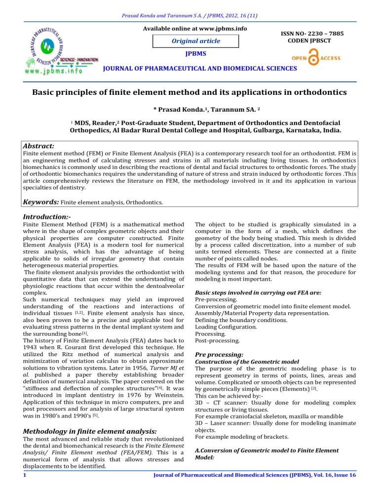
Prasad Konda and Tarannum S A. / JPBMS, 2012, 16 (11) Available online at www.jpbms.info Original article ISSN NO- 2230 – 7885 CODEN JPBSCT JPBMS JOURNAL OF PHARMACEUTICAL AND BIOMEDICAL SCIENCES Basic principles of finite element method and its applications in orthodontics * Prasad Konda.1, Tarannum SA. 2 1 MDS, Reader,2 Post-Graduate Student, Department of Orthodontics and Dentofacial Orthopedics, Al Badar Rural Dental College and Hospital, Gulbarga, Karnataka, India. Abstract: Finite element method (FEM) or Finite Element Analysis (FEA) is a contemporary research tool for an orthodontist. FEM is an engineering method of calculating stresses and strains in all materials including living tissues. In orthodontics biomechanics is commonly used in describing the reactions of dental and facial structures to orthodontic forces. The study of orthodontic biomechanics requires the understanding of nature of stress and strain induced by orthodontic forces .This article comprehensively reviews the literature on FEM, the methodology involved in it and its application in various specialties of dentistry. Keywords: Finite element analysis, Orthodontics. Introduction:Finite Element Method (FEM) is a mathematical method where in the shape of complex geometric objects and their physical properties are computer constructed. Finite Element Analysis (FEA) is a modern tool for numerical stress analysis, which has the advantage of being applicable to solids of irregular geometry that contain heterogeneous material properties. The finite element analysis provides the orthodontist with quantitative data that can extend the understanding of physiologic reactions that occur within the dentoalveolar complex. Such numerical techniques may yield an improved understanding of the reactions and interactions of individual tissues [1,2]. Finite element analysis has since, also been proven to be a precise and applicable tool for evaluating stress patterns in the dental implant system and the surrounding bone[3]. The history of Finite Element Analysis (FEA) dates back to 1943 when R. Courant first developed this technique. He utilized the Ritz method of numerical analysis and minimization of variation calculus to obtain approximate solutions to vibration systems. Later in 1956, Turner MJ et al. published a paper thereby establishing broader definition of numerical analysis. The paper centered on the "stiffness and deflection of complex structures"[4]. It was introduced in implant dentistry in 1976 by Weinstein. Application of this technique in micro computers, pre and post processors and for analysis of large structural system was in 1980’s and 1990’s [5]. Methodology in finite element analysis: The most advanced and reliable study that revolutionized the dental and biomechanical research is the Finite Element Analysis/ Finite Element method (FEA/FEM). This is a numerical form of analysis that allows stresses and displacements to be identified. 1 The object to be studied is graphically simulated in a computer in the form of a mesh, which defines the geometry of the body being studied. This mesh is divided by a process called discretization, into a number of sub units termed elements. These are connected at a finite number of points called nodes. The results of FEM will be based upon the nature of the modeling systems and for that reason, the procedure for modeling is most important. Basic steps involved in carrying out FEA are: Pre-processing. Conversion of geometric model into finite element model. Assembly/Material Property data representation. Defining the boundary conditions. Loading Configuration. Processing. Post-processing. Pre processing: Construction of the Geometric model The purpose of the geometric modeling phase is to represent geometry in terms of points, lines, areas and volume. Complicated or smooth objects can be represented by geometrically simple pieces (Elements) [2]. This can be achieved by:3D – CT scanner: Usually done for modeling complex structures or living tissues. For example craniofacial skeleton, maxilla or mandible 3D – Laser scanner: Usually done for modeling inanimate objects. For example modeling of brackets. A.Conversion of Geometric model to Finite Element Model: Journal of Pharmaceutical and Biomedical Sciences (JPBMS), Vol. 16, Issue 16 Prasad Konda and Tarannum S A. / JPBMS, 2012, 16 (11) Discretization is the process of dividing problem into several small elements, connected with nodes. All elements and nodes must be numbered so that a setup of matrix connectivity is established. This greatly affects the computing time. The elements could be one, two or three-dimensional and in various shapes. It is essential that the elements are not overlapping but are connected only at the key points, which are termed nodes. The joining of elements at the nodes and eliminating duplicate nodes is termed as ‘Meshing’. B.Assembly / Material Property data representation: Equations are developed for each element in the FEM mesh and assembled into a set of global equations that model the properties of the entire system. Minimum material properties required are poisons ratio and young’s modulus. Table 1: Material constants of Tooth, Alveolar bone, and Periodontal ligament [2] Material Young’s modulus(kg/mm2) Poisons ratio Tooth 2.6 x 10³ 0.15 PDL 6.8 x 10⁻² 0.49 Alveolar Bone 1.40 x 10³ 0.15 C.Defining the Boundary Conditions: Boundary conditions means that suppose an element is constructed on the computer and a force is applied to it, it will act like a free-floating rigid body and will undergo a translatory or rotatory motion or a combination of the two without experiencing deformation. To study its deformation, some degrees of freedom must be restricted (movement of the node in each direction x, y, and z) for some of the nodes. Such constraints are termed boundary conditions. D.Loading configuration: Application of force at various points of geometry and its configuration. Processing: Solve the system of linear algebraic equation. The stresses are determined from the strains by Hooke's law. Strains are derived from the displacement functions within the element Combined with Hooke's law. in which the field variables can be interpolated with the use of shape function. The FE analysis has the following advantages: it is a noninvasive technique; the actual amount of stress experienced at any given point can be theoretically measured; the tooth, alveolar bone, periodontal ligament, and craniofacial bones can be simulated and the material properties of these structures can be assigned to the nearest one that possibly can simulate the oral environment in vitro; the displacement of the tooth can be visualized graphically; the point of application, magnitude, and direction of a force may easily be varied to simulate the clinical situation; reproducibility does not affect the physical properties of the involved material; and the study can be repeated as many times as the operator wishes [6]. Applications of FEM: Mechanical / Aerospace/Civil/Automobile Engineering. Structure analysis (Static/dynamic, linear/no linear. Thermal / fluid flows. Electromagnetic. Geomechanics . Biomechanics. Orthopedic research. To investigate soft-tissue and skeletal responses to mechanical forces. Biomedical engineering – CAD/CAM Biomedical engineering is the application of engineering principles and design concepts to medicine and biology. This field seeks to close the gap between engineering and medicine. FEM begins with finite element modeler (mesher/preprocessor). The cost effectiveness of FEA is heavily dependent on the pre-processor since the vast majority of human time involved in finite element analysis. In order to effectively incorporate analysis into the design cycle, one must be able to quickly create the required models. The modeler creates the physical data necessary for analysis by creating mesh of elements utilizing 3D CAD model [7]. Post-Processing: The output from the Finite Element Analysis is primarily in the numerical form. It usually consists of nodal values of the field variables and its derivatives. For example in solid mechanical problems, the output is nodal displacement and element stresses. Graphic outputs and displays are usually more informative. The curves and contours of the field variable can be plotted and displayed. Also deformed shapes can be displayed and superimposed on unreformed shapes. The output is primarily in the form of color-coded maps. The quantitative analysis is determined by interpreting these maps. Discussion: FEM is a technique for obtaining a solution to a complex mechanical problem by dividing the problem domain into a collection of much smaller and simpler domains (elements) 2 Application in orthodontics Finite element modeling can be applied in three areas of biomechanics: (i) analysis of the skeleton, (ii) analysis and design of orthopedic devices and (iii) analysis of tissue growth, remodeling and degeneration. The FEM can also be applicable to the problem of stressstrain levels induced in internal structures. This method also has the potential for equivalent mathematical modeling of a real object of complicated shape and different materials. Thus, FEM offers an ideal method for accurate modeling of the tooth and periodontium with its complicated 3- dimensional geometry [2]. The force systems used on an orthodontic patient are complicated. The FEM makes it possible to analytically apply various force systems at any point and in any direction. Orthodontic tooth movement is achieved by remodeling processes of the alveolar bone, which are Journal of Pharmaceutical and Biomedical Sciences (JPBMS), Vol. 16, Issue 16 Prasad Konda and Tarannum S A. / JPBMS, 2012, 16 (11) triggered by changes in the stress/strain distribution in the periodontium. The finite element (FE) method can be used to describe the stressed situation within the periodontal ligament (PDL) and surrounding alveolar bone. It can also be used as a tool to Study Orthodontic Tooth Movement [8]. The method can be used to model intricate structures consisting of various structures consisting of various shapes and materials under complex loading. In the field of Dentistry in general, FEM has wide applicability in various specialties. In Orthodontics, FEM is one of the very important applications in the field of bio-mechanics and cranio-facial biology. The orthodontist can precisely determine the effect of various biomechanical materials involved in tooth movement and can simulate the same in treatment planning. FEM has been useful tool for morphometric analysis in craniofacial biology. The cephalometric finite element analysis (CEFEA) program incorporates the advanced features of the finite element method but bypasses the detailed understanding of the engineering and mathematics previously required to interpret results. The program uses the color graphics display of common personal computers to show size change, shape change, and angle of maximum change. These are pictured as colored triangles of clinically relevant regions between pre- and mid- or post treatment lateral head films. The program is designed to have features of interest in both clinical practice and research [9]. Drawbacks: The roots, periodontal ligament and teeth are represented in idealized geometric forms and physical properties are assumed to be homogenous, isotropic and linear. Various different methods which can also be applied are laser holography and photo elastic stress analysis. The effect of altering the geometry of the bracket base mesh on the quality of orthodontic attachment employing a three-dimensional finite element computer model is another application of FEM in orthodontics as discussed by Knox et al.[10]. The CAD/CAM template gives orthodontists safe way to place miniscrews [11]. 1. Application in other branches of dentistry FEM is widely applied mathematical method that permits us to know the biochemical behavior of the human mandible in various clinical situations under physiological and standardized trauma conditions. The 3D FEM provides to simulate force systems applied and allows analysis of the response of the Jawbone to the loads in 3D space. This virtual modeling is useful to choose the most efficient location and design of miniplate osteosynthesis and to test new biomaterials [12,13]. It is useful in dental implants; jaw bone surrounding the implant and biomechanical implant and jawbone interactions [14, 15]. In prosthodontics, FEM isuseful for dental prosthetic designing. Designs for fiber framework for FPD have been extensively investigated using FE method and FE analysis16.FEM is also used to find out Stress distributions in adhesively cemented ceramic and resin-composite class II inlay restorations [17]. In Periodontics,this application is usedto evaluate the stress distribution in periodontium based on the length, diameter, and geometry of dental implants.FEM can also be applied for prediction of face soft tissue deformations resulting from bone repositioning in maxillofacial surgery[18]. Available Commercial FEM Software Packages: ABAQUS (Non linear and dynamic) ANSYS HYPER MESH (Pre/Post processor) Conclusion: FEM is powerful analytic technique for calculating stresses and strains within mechanically loaded structures. 3 References: Geng J, Tan KBC, Liu GJ. Application of finite element analysis in implant dentistry: A review of the literature. Prosthet Dent 2001; June 585-98. 2. Kazuo Tanne, Mamoru Sakuda, Charles J. Burstone. Three dimensional finite analyses for stress distribution in the periodontal tissue by orthodontic forces. Am J Orthod Dentofacial Orthop1987; Volume 92(6):499-505. 3. Holmgren EP, Seckinger RJ, Kilgren LM, Mante F. Evaluating parameter of osseointegrated dental implant using finite element analysis – A two dimensional comparative study examining the effects of implants diameter, implant shape & load direction. J Oral Implantology1998; Vol.24 (2):80-88. 4. M.J. Turner, R.W. Clough, H.C. MactinandL.J. Topp. Stiffness and defection analysis of complex structure. J. aeronaut science1956; 23:805-823. 5. Yijunliu.Introduction to FEM –CAE research laboratory university of Cincinnati U.S.A.2003. Accessed on 13-012012 Available from URL http://ingenieria.udea.edu.co/~ingcivil/dinamica_de_e structuras/Apoyo/FEM_Lecture_Notes1.pdf 6. Alireza Jafari, K. Sadashiva Shetty, and Mohan Kumar. Study of Stress Distribution and Displacement of Various Craniofacial Structures Following Application of Transverse Orthopedic Forces-A Three-dimensional FEM Study. The Angle Orthodontist Feb 2003; 73(1):12-20. 7. Gary Davidowitz, Philip G.Kotick.The Use of CAD/CAM in dentistry. Dental clinics of North America, July 2011; 55(3):559-70. 8. P.M.Cattaneo,M.Dalstra,B. Melsen. The Finite Element Method: a Tool to Study Orthodontic Tooth Movement. JDR 2005; vol84 (5)428-33. 9. Glenn T. Sameshima and Michael Melnick. Finite element based cephalometric analysis. The Angle Orthodontist Oct 1994; 64 (5): 343-50. 10. Jeremy Knox, BerislavKralj, Dipl-Ing,PierreHubsch, Dipl-Ing, John Middleton, Malcolm L. Jones. An Evaluation of the Quality of Orthodontic Attachment Offered by Single- and Double-Mesh Bracket Bases Using the Finite Element Method of Stress Analysis. Angle orthod2001; 71(2): 149-55. Journal of Pharmaceutical and Biomedical Sciences (JPBMS), Vol. 16, Issue 16 Prasad Konda and Tarannum S A. / JPBMS, 2012, 16 (11) 11. Hong Liu, Dong-xu Liu, Guangchun Wang, Chun-ling Wang. Accuracy of Surgical Positioning of Orthodontic Miniscrews with a Computer-aided design and manufacturing template. Am J Orthod Dentofacial Orthop2010; 137(6): 728.e1-728.e10. 12. Gallas, Mercedes. "Finite Element Analysis and Its Application in Oral Surgery Research." Informatics in Oral Medicine: Advanced Techniques in Clinical and Diagnostic Technologies. IGI Global, 2010. 159-170. 13. Sarment DP, Sukovic P, Clinthorne N. Accuracy of implant placement with a sterelithographic surgical guide. Int J Oral Maxillofac Implants2003; 18(4):571-7. 14. R.C. Vanstaden, H. Guan, Y. C. Loo. Application of finite element method in dental implant research. Comput Methods Biomech Biomed Engin.2006 Aug; 9(4):25770. 15. Ruppin J, Popovic A, Strauss M, Spüntrup E, Steiner A, Stoll C. Evaluation of the accuracy of 3 different Computer Aided surgery systems in dental implantology. Clinical oral implants research2008; 19(7):709-16. 16. Akikazu Shinya and Daiichiro Yokoyama. Finite element analysis for dental prosthetic design. Accessed on 30-01-2012 Available from URL: http://www.intechopen.com/articles/show/title/finit e-element-analysis-for-dental-prosthetic-design. 17. Stress distributions in adhesively cemented ceramic and resin-composite class II inlay restorations: a 3DFEA study. Dent Mater 2004; (20): 862-872. 18. Anitua E, Tapia R, Luzuriaga F, Orive G, et al. Influence of implant length, diameter and geometry on stress distribution: a finite element analysis. Int J Periodontics Restorative Dent 2010; (30):89-95. Conflict of Interest: - None Source of funding: - Not declared Corresponding Author:Dr.Prasad Konda, Reader, Department of Orthodontics and Dentofacial Orthopedics, Al Badar Rural Dental College and Hospital, Gulbarga, Karnataka ,India. Quick Response code (QR-Code) for mobile user to access JPBMS website electronically. Website link:- www.jpbms.info 4 Journal of Pharmaceutical and Biomedical Sciences (JPBMS), Vol. 16, Issue 16 Prasad Konda and Tarannum S A. / JPBMS, 2012, 16 (11) 5 Journal of Pharmaceutical and Biomedical Sciences (JPBMS), Vol. 16, Issue 16 Prasad Konda and Tarannum S A. / JPBMS, 2012, 16 (11) 6 Journal of Pharmaceutical and Biomedical Sciences (JPBMS), Vol. 16, Issue 16 Prasad Konda and Tarannum S A. / JPBMS, 2012, 16 (11) 7 Journal of Pharmaceutical and Biomedical Sciences (JPBMS), Vol. 16, Issue 16 Prasad Konda and Tarannum S A. / JPBMS, 2012, 16 (11) 8 Journal of Pharmaceutical and Biomedical Sciences (JPBMS), Vol. 16, Issue 16

