Link-Level Analysis of Low Latency Operation in
LTE Networks
Kianoush Hosseini, Shim Patel, Aleksandar Damnjanovic, Wanshi Chen, and Juan Montojo
Qualcomm Inc., San Diego, CA, USA
Email: {kianoush, spatel, adamnjan, wanshic, juanm}@qti.qualcomm.com
CRS
frequency
DMRS
Fig. 2.
Data
Data
Data
DMRS
Data
Data
Data
Data
Data
Data
DMRS
Data
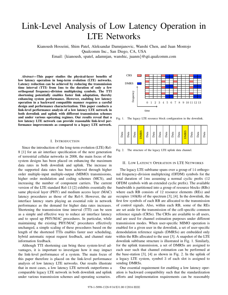
The legacy LTE resource block configuration in the downlink.
Data
Fig. 1.
I. I NTRODUCTION
Since the introduction of the long-term evolution (LTE) Rel8 [1] for an air interface specification of the next generation
of terrestrial cellular networks in 2008, the main focus of the
system designs has been placed on enhancing the maximum
data rates in both downlink and uplink. The increase in
the supported data rates has been achieved through higher
order multiple-input multiple-output (MIMO) transmissions,
higher order modulation and coding schemes (MCS), and
increasing the number of component carriers. The current
version of the LTE standard Rel-13 [2] exhibits essentially the
same physical layer (PHY) and medium access layer (MAC)
latency procedures as those of the Rel-8. However, the air
interface latency starts playing an essential role in network
performance as the demand for higher data rates increases.
Shortening the transmission time interval (TTI) can be seen
as a simple and effective way to reduce air interface latency
and to speed up PHY/MAC procedures. In particular, while
maintaining the existing PHY/MAC procedures effectively
unchanged, a simple scaling of these procedures based on the
length of the shortened TTIs enables faster user scheduling,
hybrid automatic repeat request feedback, and channel state
information feedback.
Although TTI shortening can bring these system-level advantages, it is important to investigate how it may impact
the link-level performance of a system. The main focus of
this paper therefore is placed on the link-level performance
analysis of low latency LTE networks. Our results illustrate
that in most cases, a low latency LTE network outperforms a
comparable legacy LTE network in both downlink and uplink
under various transmission schemes and operating scenarios.
0 1 2 3 4 5 6 7 8 9 10 11 12 13
time
Data
Abstract—This paper studies the physical-layer benefits of
low latency operation in long-term evolution (LTE) networks.
Latency reduction can be achieved by reducing the transmission
time interval (TTI) from 1ms to the duration of only a few
orthogonal frequency-division multiplexing symbols. The TTI
shortening potentially enables faster link adaptation, thereby
enhancing system performance. However, enabling low latency
operation in a backward compatible manner requires a careful
design and performance characterization. This paper conducts a
link-level performance analysis of a low latency LTE network in
both downlink and uplink with different transmission schemes
and under various operating regimes. Our results reveal that a
low latency LTE network can provide reasonable link-level performance improvements as compared to a legacy LTE network.
The structure of the legacy LTE uplink data channel.
II. L OW L ATENCY O PERATION IN LTE N ETWORKS
The legacy LTE subframe spans over a group of 14 orthogonal frequency-division multiplexing (OFDM) symbols for the
total duration of 1ms assuming a normal cyclic prefix (12
OFDM symbols with an extended cyclic prefix). The available
bandwidth is partitioned into a group of resource blocks (RBs)
where each RB consists of 12 resource elements (REs) and
occupies 180kHz of the spectrum [3], [4]. In the downlink, the
first few symbols of each RB are allocated to the transmission
of control signals. Also, within each RB, some of the REs
are set aside for the transmission of the cell-specific common
reference signals (CRSs). The CRSs are available to all users,
and are used for channel estimation purposes under different
transmission modes. When user-specific MIMO operation is
enabled for a given user in the downlink, a set of user-specific
demodulation reference signals (DMRSs) are embedded only
within the RBs allocated to the user [3]. A snapshot of the LTE
downlink subframe structure is illustrated in Fig. 1. Similarly,
for the uplink transmission, a set of DMRSs are assigned to
each user such that channel estimation can be performed at
the base-station [3], [4] as shown in Fig. 2. In the uplink of
a legacy LTE system, symbol 3 of each slot is assigned to
sending DMRSs.
One essential requirement for enabling a low latency operation is backward compatibility such that the standardization
efforts and implementation requirements can be reasonably
978-1-5090-1328-9/16/$31.00 ©2016 IEEE
due to an improved channel estimation quality. We show that
relying on the stale channel estimates from the past, while
exploiting all available resources for data transmission at a
lower coding rate, can be beneficial. Section IV studies the
performance of a low latency network in the uplink.
LL UE C
LL UE A
LL UE C
LL UE B
Legacy Resources
LL UE A
Legacy / LL Control
Channel Bandwidth
Legacy Resources
Fig. 3. A downlink subframe structure indicating resource allocation to
1-symbol low latency users and legacy LTE users.
managed. To this end, while the duration of the OFDM
symbols, the subcarrier spacing, and the RS patterns remain
identical to those of the legacy LTE network, the TTI of a low
latency network is reduced to only a fraction of 1ms. As an
example, the TTI length of a low latency network could be one
symbol, two symbols, or seven symbols (one slot). Further, a
network should be able to perform both the legacy LTE and
the low latency LTE operations concurrently. In this regard, the
available resources can be allocated to these two operations
in a frequency-division multiplexing and/or a time-division
multiplexing manner. While under the legacy LTE operation
resources are assigned to users on a per RB basis, under the
low latency operation, a set of few OFDM symbols spanned
over possibly multiple RBs is assigned to a user. Collision
between the two sets of resources should be avoided to the
extent possible by a base-station. An example of a downlink
subframe structure comprising both LTE and one-symbol low
latency (LL) resources is depicted in Fig. 3.
As can be seen from Fig. 1-3, one of the main challenges in
order to enable the low latency operation is that the shortened
TTIs may not contain any CRSs or DMRSs for the purpose of
channel estimation and data demodulation. As an example, a
two-symbol low latency LTE scheduled over symbols 9 and 10
of a downlink subframe includes neither CRSs nor DMRSs.
Further, as opposed to LTE networks where channel estimation
and data demodulation can rely on all RSs within a subframe
or even possibly on the future RSs, in order to reduce latency,
a low latency network must only use the past and present RSs.
In other words, while the channel estimation process can be
non-causal in an LTE network, in a low latency network, it
has to remain causal in both downlink and uplink.
In Section III, we discuss both CRS-based and DMRSbased schemes for channel estimation in the downlink of a low
latency network with multiple choices of TTI lengths. We conduct a comprehensive performance comparison between the
downlink data channel of an LTE network with that of the low
latency networks. This section also shows that bundling a set of
few consecutive RBs for DMRS-based channel estimation, as
opposed to per-RB channel estimation, significantly improves
system performance. Further, we explore the tradeoff between
the dimensional loss due to the placement of the reference
signals within each shortened TTI and the performance gain
III. D OWNLINK P ERFORMANCE A NALYSIS
This section presents performance analysis of both CRSbased and DMRS-based transmission modes in the downlink of a low latency LTE network. We discuss the main
limitations of channel estimation and data demodulation for
such networks, provide design guidelines to enhance system
performance, and conduct performance comparison between
low latency LTE and legacy LTE networks under different
operating scenarios.
A. A CRS-Based Low Latency LTE Network
To evaluate the potential benefits of TTI shortening, we consider data transmission in the downlink with a fixed transport
block size (TBS) through different TTI choices: (1) 1ms TTI,
(2) One-slot TTI, (3) two-symbol TTI, and (4) one-symbol
TTI.
The choice of the TTI length may impact system performance in two rather competing directions. First, in contrast
to the CRS-based legacy LTE networks, a low latency LTE
network can not rely on the forthcoming CRS symbols for
channel estimation since it increases latency. As an example,
a low latency transmission scheduled at time t can only
use pilots over the CRS symbols up to time t for channel
estimation. Hence, the channel estimation quality depends
critically on the distance between the CRS symbols and the
low latency symbols; as the TTI length becomes shorter,
the channel estimation quality potentially degrades. Second,
to accommodate a fixed TBS with a given MCS, as the
TTI length becomes shorter, the OFDM symbols of a low
latency network should be extended over a larger fraction of
the available bandwidth. This helps the system to leverage
frequency diversity.
In order to illustrate these points, we consider the following
cases in the numerical simulations:
1) A 1ms TTI: subframe-based transmission (2 RBs, RB
indices: 10 and 35).
2) A one-symbol TTI:
• Case A: symbol 7 of each subframe (33 RBs, RB
indices: 5-20, 27-43).
• Case B: symbol 12 of each subframe (22 RBs, RB
indices: 11-20, 27-38).
3) A two-symbol TTI:
• Case A: symbols 7 and 8 of each subframe (14 RBs,
RB indices: 10-16, 30-36).
• Case B: symbols 12 and 13 of each subframe (11
RBs, RB indices: 10-15, 30-34).
4) A one-slot TTI: the second slot of each subframe (4
RBs, RB indices: 5, 17, 30, and 42).
Note that the number of RBs in each of the low latency
systems is chosen to ensure supporting the same TBS and
TABLE I
S YSTEM D ESIGN PARAMETERS
Bandwidth: 10MHz (50 RBs)
UE speed: 3kmph, 60kmph
Control region: 2 OFDM symbols
Rank: 2
Mod. order (code rate): QPSK (1/3, 2/3)
10 0
Block error rate
Carrier frequency: 2GHz
Channel model: ETU/EPA
Number of antennas: 2Tx/2Rx
2 CRS ports
RS configuration:
2 DMRS ports
Link adaptation: disabled
10 0
10 -1
Block error rate
10 -2
10 -1
LTE
1-slot low latency
2-symbol low latency (Case A)
2-symbol low latency (Case B)
1-symbol low latency (Case A)
1-symbol low latency (Case B)
0
2
4
6
8
10
12
SNR (dB)
Fig. 5. Downlink BLER vs. SNR for a CRS-based transmission with QPSK
(1/3) and UE speed of 3kmph under the EPA channel model.
10 -2
10 -3
LTE
1-slot low latency
2-symbol low latency (Case A)
2-symbol low latency (Case B)
1-symbol low latency (Case A)
1-symbol low latency (Case B)
2
4
6
8
10
SNR (dB)
Fig. 4. Downlink BLER vs. SNR for a CRS-based transmission with QPSK
(1/3) and UE speed of 3kmph under the ETU channel model.
coding rate as those of the LTE system with 2 RBs. To
do this, the required number of RBs for the one-slot low
latency system and two-symbol low latency system under case
A is, respectively, 3.47 and 13.2. Due to the choice of an
integer number of RBs, i.e., 4 for one-slot and 14 for the
two-symbol low latency systems, they both benefit from their
slightly lower coding rate (i.e., 10 log10 (4/3.47) = 0.6dB
and 10 log10 (14/13.2) = 0.3dB, respectively.) All system
parameters are listed in Table I.
Fig. 4 and 5 compare the block error rate (BLER) of the
aforementioned networks as a function of signal-to-noise ratio
(SNR) with QPSK modulation, coding rate of 1/3, and user
equipment (UE) speed of 3kmph under both the extended
typical urban (ETU) and extended pedestrian A (EPA) channel
models. An ETU channel has a longer delay profile; hence, it
is more frequency selective as compared to an EPA channel.
Further, given the mentioned MCS, and assuming 2 RBs in
the LTE system, the TBS is 152 bits.1
As seen from Fig. 4, all low latency networks outperform
the legacy LTE. At the low-SNR regime, the one-slot system
is superior to all other cases, while at the high-SNR regime,
the one-symbol system under case A is the best option. This is
due to the fact that at low SNRs, the one-slot network benefits
from its improved channel estimation quality, while at high
SNRs, the one-symbol low latency network gains from larger
frequency diversity.
Under the EPA model, the gains due to frequency diversity
are less significant. As shown in Fig. 5, in this case, the
one-slot low latency system, which has a comparable channel
estimation quality as that of the legacy LTE and which gains
1 Such a low TBS is suitable for time-critical applications with small payload
size requirements, e.g., for industry automation, sensors, etc..
from frequency diversity as much as the one-symbol low
latency network, is superior to all other cases. Further, from
both Fig. 4 and 5, both the one-symbol and the two-symbol
low latency networks perform better under case A than case
B. This is expected since symbol 7 of each subframe is a
CRS symbol; both the one-symbol and the two-symbol low
latency networks under case A are therefore benefit from better
channel estimation quality as compared to case B.
Next, in order to highlight the impact of channel estimation,
we consider a QPSK modulation with a higher coding rate
(2/3) and a higher UE speed (60kmph). Considering the chosen MCS and the number of RBs under the LTE system, TBS
is 328 bits. The results are shown in Fig. 6. The one-slot low
latency network has a comparable channel estimation quality
with the legacy LTE. In addition, since the allocated RBs are
distributed within the available bandwidth, this scheme gains
from channel frequency diversity. As shown in this figure, a
one-slot low latency LTE network is superior to a legacy LTE
network even in the operating scenarios where the quality of
channel estimation is of utmost importance to establishing a
reliable communication. Although the two-symbol low latency
network is outperformed by the legacy LTE in lower SNRs
due to its inferior channel estimation quality, it is clearly a
better approach in the high-SNR regime. Finally, as explained
before, the one-slot and the two-symbol low latency networks
have a slightly lower coding rate. As a result, at a low to
medium SNR regime, both networks outperform a one-symbol
network. However, at the high-SNR regime, the gains due to
channel frequency diversity outweigh the coding gain. Hence,
a one-symbol TTI is the best option in this regime.
B. A DMRS-Based Low Latency LTE Network
This section provides the link-level performance analysis of
low latency networks where channel estimation and demodulation are enabled by transmitting DMRSs. Similar to the use
of CRSs, in order to ensure causality, a low latency network
is not able to exploit the future reference symbols for channel
estimation. Further, since the DMRSs are precoded, the past
DMRSs can only be used if a user is scheduled over multiple
TTIs with an identical precoding scheme.
10 0
BLER
BLER
10 0
10 -1
10 -2
LTE
1-slot low latency
2-symbol low latency (Case A)
1-symbol low latency (Case A)
4
6
8
10
12
10 -1
10 -2
14
LTE
1-slot low latency
2-symbol low latency
2
4
6
8
10
12
14
SNR (dB)
SNR (dB)
Fig. 6. Downlink BLER vs. SNR for a CRS-based transmission with QPSK
(2/3) and UE speed of 60kmph under the ETU channel model.
Fig. 8. Downlink BLER vs. SNR for a DMRS-based transmission with
QPSK (1/3) and UE speed of 60kmph under the EPA channel model.
10 0
10 0
10 -1
BLER
Block error rate
10 -1
10 -2
10 -2
10 -3
10 -3
LTE
1-slot low latency
2-symbol low latency
2
4
6
8
10
12
SNR (dB)
Fig. 7. Downlink BLER vs. SNR for a DMRS-based transmission with
QPSK (1/3) and UE speed of 60kmph under the ETU channel model.
In this section, we first assume that the past DMRSs are not
available for channel estimation. For the link-level analysis,
the following three TTI choices are considered: (1) a twosymbol TTI spanned over symbols 12 and 13, (2) a one-slot
TTI over the second slot of each subframe, and (3) a 1ms
TTI. We further assume the same DMRS configuration as in
the legacy subframe. Hence, both case (1) and (2) carry 6
DMRS resource elements per resource block. Similar to the
preceding section, the number of allocated RBs in each case
is chosen to ensure identical TBS and coding rate across these
cases. Considering the number of DMRSs per RB, with QPSK
modulation and coding rate of 1/3, the TBS is 136 bits. The
results are shown in Fig. 7 and 8 under ETU and EPA channel
models, respectively.
As illustrated in Fig. 7, under the ETU channel model and
at a low-SNR regime, the legacy LTE slightly outperforms the
other two networks due to its better channel estimation quality.
At the high-SNR regime, however, the two-symbol low latency
network which gains from frequency diversity is superior.
Under the EPA channel model, shown in Fig. 8, the legacy
LTE network is superior. As an example, at 10% block error
rate, the LTE network outperforms the one-slot low latency
network by about 2.5dB. This is mainly because, under the
10 -4
RB bundling size = 1
RB bundling size = 2
RB bundling size =5
4
6
8
10
12
14
SNR (dB)
Fig. 9. Downlink BLER vs. SNR of a DMRS-based one-slot low latency
LTE network with QPSK (1/3), UE speed of 60kmph, ETU channel model,
and under different RB bundling sizes.
EPA channel mode, the gains due to the frequency diversity are
less significant as compared to the ETU channel model. The
LTE system gains from its better channel estimation quality.
In the next section, we discuss how the performance of a
DMRS-based low latency LTE system can be improved by
increasing the RB bundling size for channel estimation.
1) Impact of RB bundling Size: As the number of RBs (and
therefore the number of DMRSs) participating in performing
minimum mean square error channel estimation increases, the
quality of channel estimation improves. Fig. 9 investigates the
impact of RB bundling size on the performance of a one-slot
low latency network spanned over 10 consecutive RBs under
ETU channel model, QPSK modulation, UE speed of 60kmph,
and with RB bundling sizes of 1, 2, and 5. A fixed precoding
matrix is employed across different RB groups.
As illustrated in this figure, at block error rate of 10%,
a low latency LTE network with RB bundling size of 2
outperforms the comparable network with RB bundling size
of 1 by about 1.5dB. By further increasing the RB bundling
size to 5, an extra 1dB performance improvement can be
achieved. It should be noted that this gain comes at a cost of
increasing the complexity of the channel estimator. However,
IV. U PLINK P ERFORMANCE A NALYSIS
This section studies the performance of uplink data transmission in a low latency network considering the following
TTI choices: (1) a one-symbol TTI, (2) a two-symbol TTI,
and (3) a one-slot TTI.
For the case of one-slot TTI, we simply take the first slot
of the legacy design and use that for transmission of the
uplink data. For the case of one-symbol and two-symbol TTIs,
10 0
BLER
10 -1
10 -2
10 -3
Symbols 5 and 6
Symbols 7 and 8
Symbols 9 and 10
10 -4
6
8
10
12
14
16
SNR (dB)
2-symbol TTI
Fig. 11.
d2 delay
Data
DMRS
Data
d1 delay
Data
Fig. 10. Downlink BLER vs. SNR of a DMRS-based two-symbol low latency
LTE network with QPSK (1/3), UE speed of 60kmph, different TTI locations
within a subframe, and under ETU channel model.
DMRS
when the number of RBs assigned to a user under both a legacy
LTE system and a low latency system is identical, channel
over a smaller number of resource elements is required to be
estimated in a low latency network. Hence, with the same level
of acceptable estimation complexity, a larger number of RBs
can be grouped together in a low latency LTE network.
2) The Impact of the TTI Location: So far, we have
assumed that each shortened TTI carries DMRSs for channel
estimation. However, the placement of the reference signals
within each shortened TTI incurs overhead. The impact of
this overhead is more pronounced as the TTI length becomes
smaller. As an example, assuming the same DMRS configuration as in the legacy LTE, the dimensional loss due to
the presence of DMRSs over a two-symbol low latency LTE
network is 25% when transmitting data with 1 or 2 layers.
Hence, a proper use of DMRSs for low latency networks
should strike a balance between channel estimation quality and
the dimensional loss due to the transmission of the reference
signals.
In this section, assuming identical precoding across multiple
consecutive TTIs, we study the possibility of exploiting the
past DMRSs for channel estimation. In particular, we consider
a user scheduled over three consecutive two-symbol TTIs
spanned over: (1) symbols 5 and 6, (2) symbols 7 and 8,
and (3) symbols 9 and 10, and 10 consecutive RBs with a
fixed TBS and precoding matrix. The considered channel is
ETU. Accounting for the presence of the DMRSs over symbols
5 and 6 and also CRSs over symbol 7, case (1) has the
largest dimensional loss, while in case (3), all the available
resources are allocated to user data transmission. Hence, case
(3) gains from a lower coding rate as compared to the other
two scenarios. However, as we move from (1) to (3), the
estimated channel becomes stale. Therefore, it is not clear
which of the three scenarios is superior from a performance
point of view.
Fig. 10 plots the block error rate of the three aforementioned
cases as a function of SNR with QPSK modulation and UE
speed of 60kmph. As shown in this figure, despite its stale
channel estimation, case (3) outperforms the other two scenarios. This shows that relying on the past channel estimates,
while using most of the available resources for providing a
lower coding rate, is beneficial. However, in general, as the
channel estimate becomes staler, it is expected that system
performance eventually degrades. Hence, updating the channel
estimates through sending new DMRSs is essential. The
periodicity of the re-transmissions can be chosen based on
the channel coherence time and the rate at which a user is
scheduled with the same precoding matrix.
1-symbol TTI
The structure of low latency uplink data channel.
similar to the downlink of a low latency LTE system, it is
not desirable to pre-determine the location of the DMRSs.
Instead, DMRSs can be more flexibly placed based on the
transmission conditions. For the purpose of evaluation, we
consider using the DMRSs placed on the past symbols as
shown in Fig. 11. Again, the TBS is computed based on the
MCS and the number of RBs in the legacy LTE system, and
is kept identical in other scenarios. Hence, the number of RBs
allocated to a one-symbol, two-symbol, one-slot, and 1ms TTI
is, respectively, 25, 12, 4, and 2. We present the simulation
results for both QPSK modulation with coding rate of 1/3 and
16QAM with coding rate of 3/4.
Fig. 12 and 13 show the system performance with QPSK
and under the ETU and EPA channel models, respectively. At
the UE speed of 3kmph, the one-symbol network outperforms
the other ones. Similar to the conclusion made in the preceding
section, this indicates that the smaller TTI durations benefit
from the increased frequency diversity gain offered by the use
of a larger bandwidth. Additionally, under the ETU channel,
both the one-symbol and two-symbol low latency networks
benefit to a larger extent from the increased frequency diversity
of the channel as compared to the EPA channel.
Fig. 14 and 15 compare the uplink performance of the
aforementioned networks with 16QAM. Due to the higher
modulation order and coding rate, channel estimation performance becomes a significant component in determining the
overall performance. Under both channel models and at the
low 3kmph UE speed, the one-symbol low latency network
is still superior. However, at the higher speed of 60kmph and
under the EPA channel, the one-symbol and two-symbol low
latency networks underperform the networks with one-slot and
10 0
10 -1
10 -1
BLER
BLER
10 0
LTE, 3kmph
1-slot, 3kmph
2-symbol, 3kmph
1-symbol, 3kmph
LTE, 60kmph
1-slot, 60kmph
2-symbol, 60kmph
1-symbol, 60kmph
10 -2
10 -3
0.5
1
10 -2
10 -3
1.5
2
2.5
3
3.5
4
LTE, 3kmph
1-slot, 3kmph
2-symbol, 3kmph
1-symbol, 3kmph
LTE, 60kpmh
1-slot, 60kmph
2-symbol, 60kmph
1-symbol, 60kmph
12
13
14
Fig. 12. Uplink BLER vs. SNR with QPSK (1/3), UE speed of 3kmph and
60kmph and under the ETU channel model.
16
17
18
19
Fig. 14. Uplink BLER vs. SNR with 16QAM (3/4), UE speed of 3kmph
and 60kmph and under the ETU channel model.
10 0
0.35
LTE, 3kmph
1-slot, 3kmph
2-symbol, 3kmph
1-symbol, 3kmph
LTE, 60kmph
1-slot, 60kmph
2-symbol, 60kmph
1-symbol, 60kmph
0.3
0.25
BLER
0.2
BLER
15
SNR (dB)
SNR (dB)
0.15
LTE, 3kmph
1-slot, 3kmph
2-symbol, 3kmph
1-symbol, 3kmph
LTE, 60kmph
1-slot, 60kmph
2-symbol, 60kmph
1-symbol, 60kmph
10 -1
0.1
0
0.5
1
1.5
2
2.5
3
3.5
4
SNR(dB)
10 -2
12
13
14
15
16
17
18
19
SNR (dB)
Fig. 13. Uplink BLER vs. SNR with QPSK (1/3), UE speed of 3kmph and
60kmph and under the EPA channel model.
Fig. 15. Uplink BLER vs. SNR with 16QAM (3/4), UE speed of 3kmph
and 60kmph and under the EPA channel model.
1ms TTI durations, which is due to their inferior channel
estimation performance. At the high speed and under the
ETU channel, there is a visible tradeoff between the channel
estimation quality and frequency diversity. In particular, for
the one-symbol and two-symbol cases, the higher slopes of
the curves indicate that these two networks benefit from the
frequency diversity of the channel. However, at the lower
SNRs, the smaller TTI durations underperform due to their
worse channel estimation performance.
channel estimation incurred by TTI shortening depends on
the TTI length, coding rate, modulation order and mobility
condition. The performance improvement due to frequency
diversity depends on the operating channel; the gains are
more pronounced under an ETU channel as compared to
an EPA channel. Our results suggest that, in most operating
regimes, a low latency network with a shortened TTI (onesymbol, two-symbol, and one-slot) provides reasonable linklevel performance improvement as compared to a legacy LTE
system in both downlink and uplink.
V. C ONCLUSION
This paper performs link-level performance evaluation of
low latency operation in both downlink and uplink of an
LTE network. In particular, the performance of a legacy LTE
network is compared with a low latency network under various
TTI lengths, different placements of the shortened TTIs within
a subframe, channel models, mobility conditions, and MCSs.
For the transmission of the same transport block size with
a fixed coding rate, as the TTI becomes shorter, a larger
fraction of the available bandwidth should be used. As a
result, although a low latency network has an inferior channel
estimation as compared to the legacy LTE, it gains from
channel frequency diversity. The performance loss due to the
R EFERENCES
[1] 3GPP TS36.300 Evolved Universal Terrestrial Radio Access (E-UTRA)
and Evolved Universal Terrestrial Radio Access Network (E-UTRAN);
Overall description; Stage 2 (Release 8).
[2] 3GPP TS36.300 Evolved Universal Terrestrial Radio Access (E-UTRA)
and Evolved Universal Terrestrial Radio Access Network (E-UTRAN);
Overall description; Stage 2 (Release 13).
[3] S. Sesia, I. Toufik, and M. Baler, LTE-The UMTS long term evolution:
from theory to practice, John Wiley & Sons, 2011.
[4] C. Johnson, Long Term Evolution IN BULLETS, 2nd Edition.

