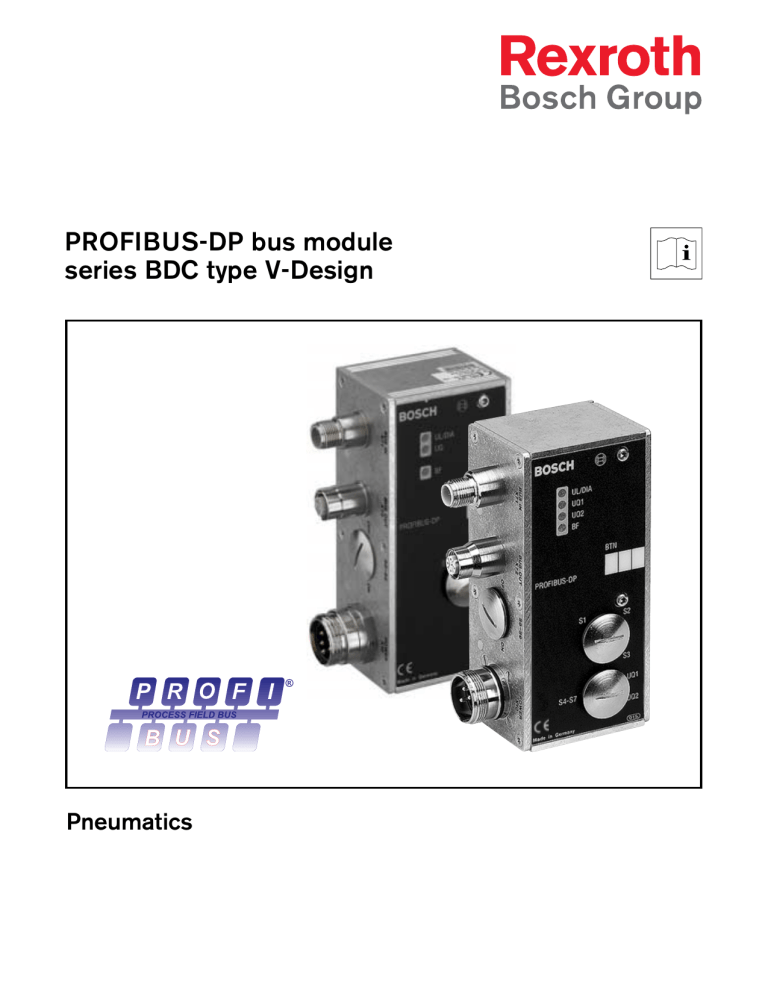
PROFIBUS-DP bus module series BDC type V-Design Pneumatics Bosch Rexroth Table of contents 3 Table of Contents Notes on safety .................................................................................... 5 1 System architecture ................................................................. 7 1.1 Construction and design ........................................................ 1.1.1 Version RMVDP/F, 1 827 030 166 ........................ 1.1.2 Version RMVDP/F_7/8", 1 827 030 205 ............. 1.2 Function ..................................................................................... 8 8 9 10 2 Presettings .................................................................................... 12 2.1 2.2 2.3 2.4 2.5 3 Baud rate ................................................................................... Setting the bus module address .......................................... Setting the operating modes (mode switch) ..................... Assigning the valve supply .................................................... Setting the bus terminator ..................................................... 12 12 14 16 17 Installation ..................................................................................... 18 3.1 Marking and identification ...................................................... 18 3.2 Bus module mounting ............................................................. 18 3.3 Electrical connections ............................................................ 19 3.3.1 Field bus connection .................................................. 19 3.3.2 Logic and load supply with RMVDP/F, 1 827 030 166 ............................................................ 21 3.3.2 Logic and load supply with RMVDP/F_7/8", 1 827 030 205 ............................................................ 23 4 Configuration ............................................................................... 25 4.1 4.2 4.3 4.4 4.5 4.6 4.7 4.8 Loading Device database ...................................................... Presetting WinDP .................................................................... Bus slave configuration .......................................................... Valve block configuration ....................................................... PLC address allocation .......................................................... Loading of master parameter set ......................................... Address assignments ............................................................. Diagnosis with WinDP ............................................................ 25 26 28 30 31 33 34 37 4 Table of contents Bosch Rexroth 5 Bus module diagnostic display ........................................... 40 6 Characteristics, service parts and accessories .......... 41 6.1 Characteristics ......................................................................... 41 6.2 Service parts and accessories ............................................. 42 Bosch Rexroth Notes on safety 5 Notes on safety ☞ Please observe the notes on safety and familiarise yourself thoroughly with the contents of the operating instructions before installing the valve block system and connecting it to the compressed air or electrical systems. The RMVDP/F 1) bus module is exclusively designed for operation as a slave on a PROFIBUS-DP bus system (EN 50170 part 2). Systems with the RMVDP/F 1) bus module may only be used for industrial applications. An individual license must be obtained from the authorities or an inspection centre for systems with RMVDP/F components that are to be used in a residential area (residen-tial, business and commercial areas). 2) 1 ) Order code Order number RMVDP/F 1 827 030 166 RMVDP/F_7/8" 1 827 030 205 2 ) In Germany, these individual licenses are issued by the Regulating Agency for Telecommunications and Post (Regulierungsbehörde für Telekommunikation und Post RegTP). 6 Notes on safety Bosch Rexroth Installation may only be performed in a voltage- free and pressure-free state and by a qualified technician. In order to avoid accidents, electrical start-up is to be carried out only in a pressurefree state. Ground the valve block system. Please observe the following standards with the installation of the system: VDE 0160 (DIN EN 50178) VDE 0100 Before connecting or disconnecting the plugs, switch off the operating voltage to prevent damage to the electrical system. Do not put the valve block system into operation before it is completely assembled as well as correctly wired and tested. Validity These operating instructions apply to – the PROFIBUS-DP bus module (RMVDP/F and RMVDP/F_7/8") series BDC type V-Design in conjunction with a series VTS 02, HF 03 / HF 02, MC valve block system with a multiple plug connector. Bosch Rexroth 1 System architecture 7 System architecture The versatility and flexibility of this valve block system enables Bosch Rexroth to support your automation tasks. The valves are completely assembled and tested according to your requirements; the electrical connection is made via decentralised bus modules. The valve block system in the local and external pilot control versions is then ready for use. Its modular construction allows existing systems to be expanded or converted at any time. The valve block system's operating instructions are composed of individual components. Valve Block systems with a multiple plug connector: – series VTS 02, HF 03 / HF 02, MC – Bus modules series BDC type V-Design: PROFIBUS-DP INTERBUS CANopen DeviceNet type A-Design: AS Interface – Modules series DDL type V-Design: DDL / DDL-E UL/DIA UQ1 UQ2 BF Figure 1-1: System architecture BDC = Bus Direct Control DDL = Drive & Diagnostics Link 8 System architecture Bosch Rexroth 1.1 BUS IN X71 and BUS OUT X72 Construction and design Connections for the field bus PROFIBUS-DP, for control of the valves. 1.1.1 Version RMVDP/F, 1 827 030 166 POWER X10 plug 6-pin M23 Electrical connection for – valve solenoids and – logic. Control elements – 2 rotary switches, S1 and S2, for setting the DP station address. – 8-position DIL switch S3 for mode settings. – 4 slide switches, S4 to S7, for assigning valves to the supply voltage in groups (before or after the emergency off). – 2 slide switches, S8 and S9, for terminating the bus. BUS IN X71 UL/DIA UQ1 UQ2 BF PROFIBUS-DP 132 OFF S8-S9 S1 BUS OUT X72 BTN S2 ON S3 UQ2 015 Made in Germany 60 (77.5) POWER X10 UQ1 S4-S7 49.4 50 53.9 Figure 1-2: PROFIBUS-DP bus module RMVDP/F dimensioned drawing Bosch Rexroth System architecture 1.1.2 9 Version RMVDP/F_7/8", 1 827 030 205 POWER X10 plug 5-pin 7/8" Electrical connection for – valve solenoids and – logic. Control elements – 2 rotary switches, S1 and S2, for setting the DP station address. – 8-position DIL switch S3 for mode settings. – 2 slide switches, S8 and S9, for terminating the bus. BUS IN X71 UL/DIA UQ BF PROFIBUS-DP 132 OFF S8-S9 S1 BUS OUT X72 BTN S2 ON S3 POWER X10 015 Made in Germany 60 (81) 49.4 50 53.9 Figure 1-3: PROFIBUS-DP bus module RMVDP/F_7/8" dimensioned drawing 10 System architecture 1.2 Bosch Rexroth Function The bus module PROFIBUS-DP (RMVDP/F and RMVDP/F_7/8") is exclusively designed for operation as a bus participant (slave) on a PROFIBUS-DP bus system according to EN 50170. A twisted, shielded pair of wires is used as a field bus cable. The bus length can be up to 1.2 km (without a repeater) depending on the transfer rate. Without a repeater, 32 bus particpants (slaves) per segment are connectable. With repeaters, it is expandable up to 127 bus partcipants (slaves). Station address The DP station address of the bus module is set using the two rotary switches, S1 and S2. Baud rate The bus module automatically adjusts to the bus speed between 9.6 kBaud and 12 MBaud. Diagnosis The supply voltage for logic and valve control is monitored. If the value falls below the set threshold, an error signal is generated and the diagnostic information is reported via LEDs. Bosch Rexroth LED System architecture Signal Error Description UL/DIA green UQ1 UQ2 1) BF 11 Logic supply UL present. off No logic supply UL available. red Valve driver overload (DIA group diagnosis). This display only occurs as long as the overloaded output is triggered. green Valve supply UQ1 is OK. red Low voltage (12 V < UQ1 < 18.5 V) off Valve supply UQ1 < 12 V green Valve supply UQ2 is OK. red Low voltage (12 V < UQ2 < 18.5 V) off Valve supply UQ2 < 12 V off Baud rate was synchronised. RUN: cyclical data exchange red Bus error: bus module baud rate is being determined, or wiring error. Table 1-1: Bus module diagnostic display 1 ) Only for RMVDP/F - 1 827 030 166 12 2 Presettings Bosch Rexroth Presettings 2.1 Baud rate The bus module automatically sets itself to the baud rate given by the busmaster. The maximum permissible baud rates are: Permissible baud rates kBaud kBaud MBaud 9.6 187.5 3 19.2 500 6 93.75 1.500 12 Table 2-1: Permissible baud rates 2.2 See figure 2-1 ☞ Setting the bus module address After the PG screw cap on the bus module is opened, both rotary switches, S1 and S2, become accessible for defining the station address for the valve block system in PROFIBUS-DP. Using S1 and S2, the station address can be assigned as desired from 1 to 99. The bus module is delivered with a factory-set station address of "0". If the bus module's ASIC recognises the non-permitted value "0" when connected, the station address 126 is assigned automatically until the user sets the station address to the desired value using S1 and S2. Double occupancies are not allowed within the PROFIBUS-DP. Bosch Rexroth Presettings 13 The set address is read once by the bus module's ASIC when the power supply UL is connected. If address changes are made, the power supply must be disconnected and then reconnected. The setting of the S1 rotary switch determines the tens place (set value * 10). The setting of the S2 rotary switch determines the ones place (set value * 1). The sum of the two settings provides the station address. Address switch (rotary switches S1 and S2) Rotary switch S1 S2 Setting range 0 ... 9 0 ... 9 10 1 0 ... 90 0 ... 9 Grading Address range Table 2-2: Address switch S1 and S2 assignment Figure 2-1: Address switches S1, S2 and mode switch S3 14 Presettings Bosch Rexroth 2.3 Setting the operating modes (mode switch) The S3 mode switch for setting the diagnostic messages is located below the PG screw cap. See figure 2-1 ☞ All switches are in the OFF position on delivery. Switches S3.8 to S3.6 are not assigned. S3.5 S3.4 S3.3 S3.2 S3.1 Message OFF off ON on OFF off ON on OFF off ON on OFF off ON on OFF off ON on Diagnosis Valve driver overload Low voltage UQ1 Low voltage UQ2 1) Emergency off UQ1 Emergency off UQ2 1) Table 2-3: Mode switch S3 for diagnostic messages to the master 1 ) Only for RMVDP/F - 1 827 030 166 Bosch Rexroth Presettings 15 If a particular switch is ON, the diagnostic message described is sent to the bus. Valve driver overload message Switch S3.1 Diagnostic message if a valve incorrectly shows a short circuit. The diagnostic message is only on as long as this valve is being triggered. Low voltage message 1) Switch S3.2 UQ1 Switch S3.3 UQ2 2) The switching voltage must be 18 V in order to guarantee safe switching! Low voltage for the valves means that the UQ voltage must lie between 12 V and 18.5 V. Emergency off message Switch S3.4 UQ1 Switch S3.5 UQ2 2) If a voltage lower than 12 V occurs, this is reported as an emergency off message. 1 ) After approx. 10 ms when turning on. After approx. 20 ms when turning off. 2 ) Only for RMVDP/F - 1 827 030 166 16 Presettings Only for RMVDP/F 1 827 030 166 Bosch Rexroth 2.4 Assigning the valve supply Switches S4-S7 for assigning the valve supply are located below the PG screw cap. 4 valve positions (each with solenoids 12 and 14) are assigned to each switch. Each valve group can be assigned one of the two supply voltages, UQ1 and UQ2, via the position of the switches S4-S7. Example If, for example, the supply voltage UQ1 is fed through the emergency off and UQ2 is not, the valves that are supplied by UQ2 remain functioning in case of an emergency off. ☞ All switches are in the UQ1 position on delivery, meaning that all valve positions are assigned to supply voltage UQ1. Switches S4-S7 may only be switched in an idle state! Assigning switches to valve groups Valve positions 1-4 5-8 9-12 13-16 Assigning switch positions to the supply voltages UQ1 and UQ2 Figure 2-2: Switches S4-S7 Bosch Rexroth Presettings 2.5 17 Setting the bus terminator In order to minimise wire reflection and ensure a defined idle level in the PROFIBUS-DP transmission line, the transmission line must be equipped with a bus terminator at both ends. The bus terminator is integrated in the equipment for bus module RMVDP/F. Switches S8-S9 are located below the PG screw cap. ☞ Both switches are in the OFF position on delivery, meaning that the bus terminator is not activated. If the bus module is attached at the end of the transmission line, the bus terminator must be activated. Switch position Bus terminator, switch positions S8-S9 Bus terminator S8 S9 OFF OFF Deactivated ON OFF Not allowed OFF ON Not allowed ON ON Activated Table 2-4: Bus terminator, switches S8-S9 Switches S8-S9 Figure 2-3: Switches S8-S9 18 3 Installation Bosch Rexroth Installation ✍ 3.1 Marking and identification The address provided/used for the bus module is inscribed on the bus module in the bus participant's (slave) field. 3.2 Bus module mounting The bus module is placed on the multiple plug connector of the valve block system and screwed tight. ☞ Check the gasket to ensure it is intact and make sure that it is in the correct position. The bus module should only be assembled (attaching to and removing from the valve block system) when the voltage is switched off! Once the bus module has been mounted, the IP 65 seal needs to be checked in accordance with EN 60529. Gasket Figure 3-1: Bus module mounting on the valve block system's multiple plug connector Bosch Rexroth See table 3-1 BUS IN X71 and BUS OUT X72 assignment See section 2.5 Bus terminator Installation 3.3 Electrical connections 3.3.1 Field bus connection 19 – The BUS INX71 plug for connecting the incoming field bus cable and – the BUS OUTX72 socket for connecting the outgoing field bus cable are located on the RMVDP/F bus module. If it is the last station in the field bus connection, the remote bus is only connected to BUS IN X71 and closed via switches S8-S9 using the bus terminator supplied internally. A PG protective cap is put on the BUS OUTX72 socket. BUS IN X71 BUS IN X71 PG protective cap BUS OUT X72 Figure 3-2: Two-way field bus connection Figure 3-3: Field bus connection as the last station 20 Installation Bosch Rexroth If not otherwise specified, the installation guidelines for PROFIBUS-DP/FMS (PROFIBUS guideline, PNO order no. 2.111) must be observed. Only a cable that meets the field bus specifications as well as the connection speed and length requirements should be used. In order to assure both the degree of protection and the required strain relief, the cable and plug assembly should be performed specifically according to the assembly instructions. This connection technology and plug assignment meet the specifications of the technical guideline for "Connection technology for PROFIBUSDP/FMS/PA" (Draft 2.0, April 1999). BUS IN X71 and BUS OUT X72 assignment Pin Signal Meaning 1 VP Supply voltage plus (P5V) 2 RxD/TxD-N Received/transmitted data data line A (green) 3 DGND Data reference potential, 0V 4 RxD/TxD-P Received/transmitted data data line B (red) 5 Shield Shield or protective ground Casing Shield or protective ground Table 3-1: BUS IN X71 and BUS OUT X72 assignment Bosch Rexroth Installation 3.3.2 21 Logic and load supply with RMVDP/F, 1 827 030 166 POWER X10 The valves and the bus module are all powered via the plug POWER X10. See section 6.2 The bus module operating voltages must be connected via the coupling socket (accessories) in accordance with Table 3-2. See section 6.1 The operating voltages given in the electrical data characteristics must be adhered to. The 24-V supply can be obtained from a common power supply unit. This power supply must stem from a power supply unit which is electrically isolated according to DIN EN 60742, classification VDE 0551. POWER X10 plug pin assignments (bus module RMVDP/F) Pin POWER X10 Assignment 1 PE Protective ground (protruding contact) 2 UQ1 First supply voltage,Valves 3 0VUQ Ground for UQ1 4 UL Supply voltage Bus module logic 5 0VUL Ground for UL 6 UQ2 Second supply voltage, Valves Table 3-2: POWER X10 plug assignment on the bus module RMVDP/F Voltages UQ and UL are galvanically isolated from each other but can be obtained from a common power supply. 22 Installation Bosch Rexroth The following current levels must be provided. The cable cross-sections must be selected according to the cable length and the operating current: POWER X10 power consumption (bus module RMVDP/F) Signal Assignment Total current UL Logic max. 0.2 A UQ1 Valves max. 2.25 A UQ2 Valves max. 2.25 A Table 3-3: POWER X10 power consumption Figure 3-4: POWER X10 on the bus module RMVDP/F Bosch Rexroth Installation 3.3.2 23 Logic and load supply with RMVDP/F_7/8", 1 827 030 205 POWER X10 The valves and the bus module are all powered via the plug POWER X10. See section 6.2 The bus module operating voltages must be connected via the coupling socket (accessories) in accordance with Table 3-4. See section 6.1 The operating voltages given in the electrical data characteristics must be adhered to. The 24-V supply can be obtained from a common power supply unit. This power supply must stem from a power supply unit which is electrically isolated according to DIN EN 60742, classification VDE 0551. POWER X10 plug pin assignments (bus module RMVDP/F_7/8") Pin POWER X10 Assignment 1 0VUQ Ground for UQ 2 0VUL Ground for UL 3 PE Protective ground (protruding contact) 4 UL Supply voltage Bus module logic 5 UQ Supply voltage,Valves Table 3-4: POWER X10 plug assignment on the bus module RMVDP/F_7/8" Voltages UQ and UL are galvanically isolated from each other but can be obtained from a common power supply. 24 Installation Bosch Rexroth The following current levels must be provided. The cable cross-sections must be selected according to the cable length and the operating current: POWER X10 power consumption (bus module RMVDP/F_7/8") Signal Assignment Total current UL Logic max. 0.2 A UQ Valves max. 2.25 A Table 3-5: POWER X10 power consumption POWER X10 4 3 UL AC 24 V 0VUL PE 2 1 5 UQ 24 V 0VUQ Figure 3-5: POWER X10 on the bus module RMVDP/F_7/8" AC Bosch Rexroth 4 Configuration 25 Configuration ☞ The description in this section refers to the software WinDP, Version 1.94, running under Windows 95, 98 and NT. Bosch order no. 1 070 077 945. 4.1 Loading Device database The Device database includes the performance characteristics of the DP slave or DP master. The Device database is standardised in accordance with EN 50170, part 2, PROFIBUS. In this way, DP components from different vendors can be implemented with one planning software package. Each valve block system is equipped with valves as ordered and it must now be configured as a DP slave using the WinDP programme (Bosch). To plan with the valve block system using Bosch WinDP the Device database files must be copied to the subdirectory GSD, ex.: \Device database (GSD)\PROFIBUS\DP\GSD. For more details, see the "README" file on the Device database diskette. The diskette with the Device database or type files, Bosch order no. 1 070 075 547, includes all module data for the valve block systems. 26 Configuration Bosch Rexroth 4.2 Presetting WinDP The WinDP utility programme runs on top of WinSPS. Only existing PLC projects can be worked on with the WinDP software. Therefore, after start up, WinDP searches for the directory where the PLC project is located. The project name found there is then put into the "Presets" field. The directory that the Device database was copied to must also be identified (see section 4.1). Figure 4-1: WinDP Presets menu Bosch Rexroth Configuration 27 After confirming with OK, you must select the busmaster built into your control in the "Busmaster selection" window. You then enter the WinDP editor, where you configure the PROFIBUS-DP. In the work space of the editor, the first hierarchical level contains the busmaster you specified, assigned to bus address 1. Figure 4-2: Busmaster selection menu 28 Configuration Bosch Rexroth 4.3 See figure 4-3 Bus slave configuration In the bus slave window all slaves are displayed whose Device database files lie in the directory that was entered into the "Device database path" in the section "WinDP Presets" (see 4.2). In order to configure the valve block system as a slave in the PROFIBUS-DP, select the valve block system bus module in the "Bus slave" window. The bus module is designated as “RMVDP/F”. 1) Click on the bus slave “RMVDP/F”, and hold down the left mouse button dragging the bus slave toward the left to the busmaster and into the work area. As soon as a square with a + appears under the mouse pointer, release the left mouse button and the bus slave is then dropped. WinDP draws the bus line from the master to the new bus slave “RMVDP/F” and assigns it to the next available bus address. If the bus address does not agree with the address on the bus module (the address assigned in section 2.2), the address field in the work area can be opened by double clicking and the addresses can be corrected there. 1 ) For RMVDP/F and RMVDP/F_7/8" Bosch Rexroth Configuration 29 ➁ 2a 2b ➀ ➂ Figure 4-3: WinDP Editor menu, configuring the DP slave RM, window designations ➀ ➁ ➂ Work area Bus slave window 2a Bus module designation 2b Valve block system I/Q window 30 Configuration Bosch Rexroth 4.4 Valve block configuration Because the valve block system is a modularly constructed slave, the valve block must now be added to the bus module. By double clicking on the "RMVDP/F" bus slave in the bus slave window, all available modules for this bus slave are displayed. By clicking and then dragging, set the valve block "valves 1-16" on the bus module in the working window. ☞ Only the maximum number of available valve positions (connection plates) on the valve block is the deciding factor for choosing the module. The number of valves is not significant! The valve block must always have the module number M0. Configurations with more than one valve block on one bus module are not permissible. In order to activate the valves, you must assign PLC outputs to the output bytes. WinDP automatically shows the number of bytes that will be transferred on the PROFIBUS-DP. There are always 4 output bytes with HF valves. The byte transfer on the PROFIBUS-DP does not depend on whether these bytes are allocated to PLC outputs. Bosch Rexroth Configuration 4.5 See figure 4-4 31 PLC address allocation All – Inputs (I), – Outputs (Q), – Extended Inputs (EI) and – Extended Outputs (EQ), as well as special channels are listed in the I/Q window of WinDP. The selection of the PLC address space was taken into account in the presetting stage. If symbol files are defined there, the symbols and symbol comments of all inputs and outputs are displayed. Select field Q for outputs and then a free PLC output and click on it in the I/Q window. By holding down the left mouse button, the output can be dragged and dropped on a valve block output byte in the work space. In the example, the PLC output Q0 was allocated to the first output byte of the valve block system, Q1 to the second, etc. 32 Configuration Bosch Rexroth Figure 4-4: WinDP Editor menu, assigning PLC addresses After the drop, WinDP assigns the address of the bus slave to the PLC output in the I/Q window. You can immediately see which PLC addresses are still available. ☞ If a change-over valve is later replaced by an impulse valve, the bus module must be newly configured, in case the necessary PLC outputs are not occupied. We recommend that PLC addresses be allocated to all input and output bytes! Bosch Rexroth Configuration 4.6 Only for BM DESI-DP12 See section 2.2.2 See figure 4-5 33 Loading of master parameter set Before you make a connection to the busmaster, you must check and, if required, adjust the busmaster DIP switch positions. The busmaster coupling field is set by the DIP switch S4. After all PROFIBUS-DP slaves are configured, the information in the busmaster file must be transferred together with the bus parameters set in WinDP (baud rate, etc.) to the busmaster. To do this, select the menu item "File, Load". WinDP prepares the master parameter set MPS, containing all data needed for operation of the busmaster, slave and bus system PROFIBUS-DP and then transfers this information to the busmaster. Figure 4-5: WinDP Editor menu, Loading of master parameter set The busmaster is stopped during the loading process. A dialogue window appears with a prompt. Select "Yes" to execute the loading process. After the loading process is complete, the busmaster is restarted, again based on a prompt. After the MPS is read, all of the PLC input and output adresses of the slaves are recognised by the busmaster. 34 Configuration Bosch Rexroth Now the UL/DIA LED on the valve block system's bus module must illuminate continuously and the BF LED should be off. The status display on the busmaster must extinguish (see the busmaster handbook). 4.7 Address assignments Valve block address assignment To be able to activate specific valves, it is necessary to allocate the bits of a PLC output to the individual valve positions on the valve block. Also see table 4-1a and table 4-1b If you have allocated a 12-position valve block to PLC addresses Q0 to Q2, the individual bits of these 3 bytes should be set up according to tables 4-1a and 4-1b. ☞ Valve block systems with up to 8 valve positions occupy only 2 byte addresses, Q0 and Q1. Connection 0 corresponds to bit 0. Bosch Rexroth Address assignment on the valve block, valve positions 1-8 Configuration Valve position Solenoid/ LED Byte Address 1 14 0 Q0.0 2 3 4 5 6 7 8 12 Q0.1 14 Q0.2 12 Q0.3 14 Q0.4 12 Q0.5 14 Q0.6 12 Q0.7 14 1 35 Q1.0 12 Q1.1 14 Q1.2 12 Q1.3 14 Q1.4 12 Q1.5 14 Q1.6 12 Q1.7 Table 4-1a: Address assignment on a valve block for valve positions 1-8 ☞ Change-over valves only use solenoid 14. 36 Configuration Address assignment on the valve block, valve positions 9-16 Bosch Rexroth Valve position Solenoid/ LED Byte Address 9 14 2 Q2.0 10 11 12 13 14 15 16 12 Q2.1 14 Q2.2 12 Q2.3 14 Q2.4 12 Q2.5 14 Q2.6 12 Q2.7 14 3 Q3.0 12 Q3.1 14 Q3.2 12 Q3.3 14 Q3.4 12 Q3.5 14 Q3.6 12 Q3.7 Table 4-1b: Address assignment on a valve block for valve positions 9-16 ☞ Change-over valves only use solenoid 14. Bosch Rexroth Configuration 4.8 See section 5 Diagnostic display 37 Diagnosis with WinDP Diagnosis with WinDP and the diagnostic display on the bus module can provide information on errors if the LEDs UL/DIA on the bus module do not illuminate continuously or one of the UQ1 or UQ2 LEDs is lit or if there is a message on the status display of the busmaster. To use the diagnosis in WinDP click on the menu option "View, Diagnostic". Detailed error and diagnostic messages from the busmaster and slaves are logged in the diagnosis output. Here the PROFIBUS-DP along with the programmer (address 0), the busmaster (address 1) and the fields for the slaves (bus slaves with addresses 2 to 125) are displayed in the upper half of the window. See figure 4-6 In the example in figure 4-6, the slave at address 2 reports an error and address field 2 has a red background. If the bus slave is clicked on, the corresponding diagnostic message is received in the text window: "Bus station can not be reached." See figure 4-7 In the example in figure 4-7, the slave at address 2 reports an error and address field 2 has a yellow background. The message shows an equipmentrelated diagnosis: "Low voltage UQ1" and "UQ2 not existing". 38 Configuration Bosch Rexroth Figure 4-6: Diagnostic window with configuration error Figure 4-7: Diagnostic window with voltage error Bosch Rexroth Configuration 39 After the error has been corrected and after the correct master parameter set is loaded into the busmaster, the diagnosis should display an errorfree PROFIBUS-DP. Module data If you click a module using the right mouse button in the bus slave window in WinDP, the Module data window opens and the module's configuration data is displayed. Figure 4-8: Module data window 40 Bus module diagnostic display 5 Bosch Rexroth Bus module diagnostic display The LEDs on the front panel of the bus module show the messages of the following table. The diagnostic display works independently of the mode switch's settings in section 2.3. LED Signal Error Description UL/DIA green UQ1 UQ2 1) BF UL logic supply present. off No UL logic supply present. red Valve driver overload (DIA group diagnosis). This display only occurs as long as the overloaded output is triggered. green UQ1 valve supply is OK. red Low voltage (12 V < UQ1 < 18.5 V) off UQ1 valve supply < 12 V green UQ2 valve supply is OK. red Low voltage (12 V < UQ2 < 18.5 V) off UQ2 valve supply < 12 V off Baud rate was synchronised. RUN: cyclical data exchange. red Bus error: bus module baud rate is being determined, or wiring error. Table 5-1: Bus module diagnostic display 1 ) Only for RMVDP/F - 1 827 030 166 Bosch Rexroth Characteristics, service parts and accessories 6 Characteristics, service parts and accessories 6.1 Characteristics General Installation position Any Degree of protection EN 60529/IEC 60529 Ambient temperature IP 65 when assembled ϑU +5 °C to +50 °C Electrical Rated voltage logics Un 24 V DC (15 % / +20 %) Rated voltage output Un 24 V DC (15 % / +20 %) Electromagnetic compatibility EN 61131-2; 1994 Interference immunity EN 50081-2; 1993 Interference signal 41 42 Characteristics, service parts and accessories 6.2 Bosch Rexroth Service parts and accessories Order code Order number RMVDP/F 1 827 030 166 RMVDP/F_7/8" 1 827 030 205 Bus module for PROFIBUS-DP * * Delivery includes fastening screws and gasket Accessories Order number Plug connection M23, Soldered contact connection for voltage supply, 6-pin socket M23, Screwed contact connection for RMVDP/F Plug connection 7/8", Screwed contact connection for voltage supply, 5-pin socket 7/8", Screwed contact connection for RMVDP/F_7/8" Plug connection for bus connection, 5-pin plug, screwed contact connection Plug connection for bus connection, 5-pin socket, screwed contact connection M12 protective cap Device database, GSD diskette, 3 1/2" Bus cable, solid, PVC Bus cable, solid, oil and grease resistant Trailing cable, PUR, tensile force 100 N Trailing cable, PUR, tensile force 20 N,oil and grease resistant 1 824 484 053 Address 1) Franz Binder GmbH & Co. Rötelstrasse 27 D-74172 Neckarsulm 2) Murrelektronik GmbH Postfach 11 65 D-71570 Oppenweiler Cable way 1 824 484 030 Supplier 1) Supplier 2) 1 824 484 026 1 824 484 027 1 823 312 001 1 070 075 547 1 070 917 202 1 070 919 661 1 070 917 201 1 070 919 660 Order number 6-8 mm Socket straight 92-2444-12-05 10-12 mm Socket straight 99-2444-32-05 6-8 mm 6-9,5 mm Socket angled 99-2444-52-05 Socket straight 00 027 661 Bosch Rexroth AG Pneumatics Bartweg 13 D-30453 Hannover Tel.: 05 11 / 21 36 - 0 Fax.: 05 11 / 21 36 - 2 69 E-Mail: [email protected] www.boschrexroth.de/pneumatics US Bosch Rexroth Corporation Pneumatics P.O. Box 13597 1953 Mercer Road Lexington, KY 40511-1021 Phone: 859-254-8031 Fax: 859-254-4188 BRP/VMK2(Si) • Printed in Germany Your concessionary 1 987 765 434 (03.02) en • Subject to technical modification

