Final Diseño LAB1 - Proyectosfie.COM
Anuncio
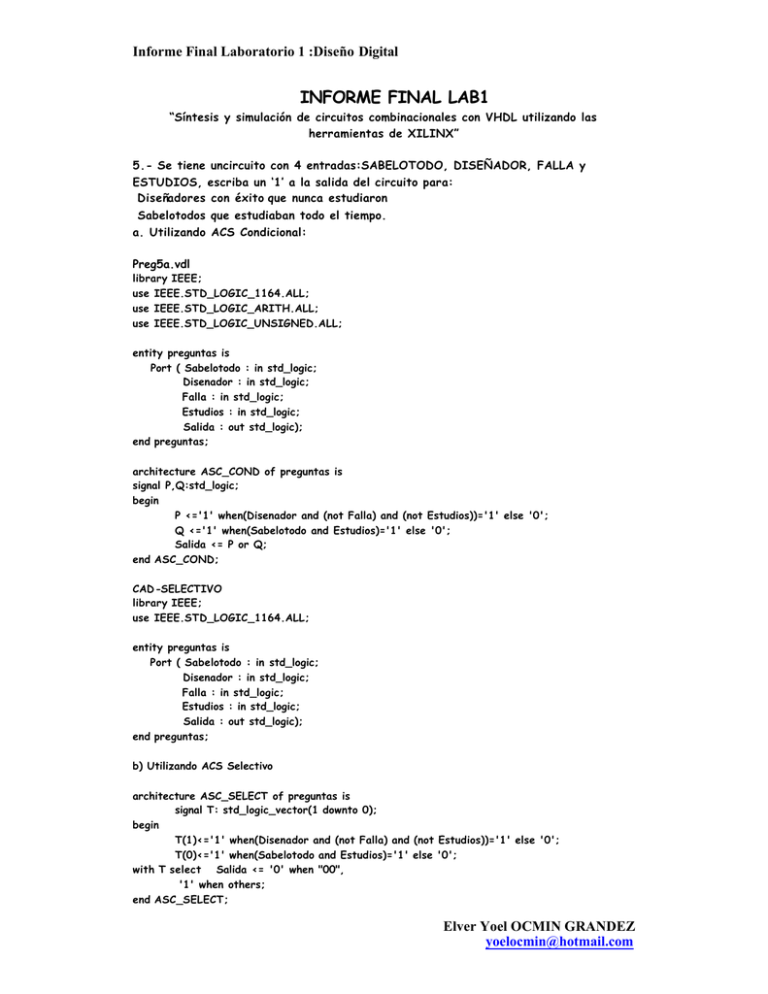
Informe Final Laboratorio 1 :Diseño Digital INFORME FINAL LAB1 “Síntesis y simulación de circuitos combinacionales con VHDL utilizando las herramientas de XILINX” 5.- Se tiene uncircuito con 4 entradas:SABELOTODO, DISEÑADOR, FALLA y ESTUDIOS, escriba un ‘1’ a la salida del circuito para: Diseñadores con éxito que nunca estudiaron Sabelotodos que estudiaban todo el tiempo. a. Utilizando ACS Condicional: Preg5a.vdl library IEEE; use IEEE.STD_LOGIC_1164.ALL; use IEEE.STD_LOGIC_ARITH.ALL; use IEEE.STD_LOGIC_UNSIGNED.ALL; entity preguntas is Port ( Sabelotodo : in std_logic; Disenador : in std_logic; Falla : in std_logic; Estudios : in std_logic; Salida : out std_logic); end preguntas; architecture ASC_COND of preguntas is signal P,Q:std_logic; begin P <='1' when(Disenador and (not Falla) and (not Estudios))='1' else '0'; Q <='1' when(Sabelotodo and Estudios)='1' else '0'; Salida <= P or Q; end ASC_COND; CAD-SELECTIVO library IEEE; use IEEE.STD_LOGIC_1164.ALL; entity preguntas is Port ( Sabelotodo : in std_logic; Disenador : in std_logic; Falla : in std_logic; Estudios : in std_logic; Salida : out std_logic); end preguntas; b) Utilizando ACS Selectivo architecture ASC_SELECT of preguntas is signal T: std_logic_vector(1 downto 0); begin T(1)<='1' when(Disenador and (not Falla) and (not Estudios))='1' else '0'; T(0)<='1' when(Sabelotodo and Estudios)='1' else '0'; with T select Salida <= '0' when "00", '1' when others; end ASC_SELECT; Elver Yoel OCMIN GRANDEZ [email protected] Informe Final Laboratorio 1 :Diseño Digital 6.- Diseñe un Circuito sumador completo de 2 bits c/u -a1 a0 ____________ _ -| |___ | ___ | S1 S0 -|______ | | |_____| | -| \ "2" |_______ | -Cin ------ | > |_____ -_____ | / bits | | -| __ | |___ | Cout -| | |_____________| -b1 b0 -library IEEE; use IEEE.STD_LOGIC_1164.ALL; entity Preg6 is Port ( a : in std_logic_vector(1 downto 0);--entradas a de 2 bits b : in std_logic_vector(1 downto 0);--entradas b de 2 bits cin : in std_logic;--Carry entrada cout : out std_logic;--Carry salida sum : out std_logic_vector(1 downto 0));--salida sum de 2 bits end Preg6; architecture flujo of Preg6 is --Sum2bits signal temp,temp2: std_logic_vector(1 downto 0); --Sirve para las sumas parciales begin temp2(0) <= (a(0) and b(0))xor cin; --carry 0 temp(0) <= (a(0) xor b(0)) xor cin; --a(0)+b(0)+Cin temp(1) <= (a(1) xor b(1)) xor temp2(0); --a(1)+(b1)+temp2(0) temp2(1) <= (a(1) and b(1)) xor temp2(0); --carry 1 sum <=temp; cout <=temp2(1); end flujo; 7.-Escriba el programa en VHDL, para el siguiente circuito: PREG7.VHD library IEEE; use IEEE.STD_LOGIC_ 1164.ALL; entity Preg7 is --MUX2A1 Port ( A : in std_logic; B : in std_logic; Sel : in std_logic; Z : out std_logic); end Preg7; architecture Flujo of MUX2A1 is begin Z<=A When Sel ='0' ELSE B; end Flujo; Elver Yoel OCMIN GRANDEZ [email protected] Informe Final Laboratorio 1 :Diseño Digital 8.- Escriba el programa en VHDL para un decodificador a 7 segmentos con una entrada de control. PREG8.VHD --DECODER HEX a 7 Segmentos -- HEX: in STD_LOGIC_VECTOR (3 downto 0); -- LED: out STD_LOGIC_VECTOR (6 downto 0); --- segment encoding _0__ -5 | | 1 -| __ |ß ß 6 -4 | | 2 -|___ | -3 library ieee; use ieee.std_logic_1164.all; entity Preg8 is port( control: in std_logic; bcd: in std_logic_vector(3 downto 0); LED: out std_logic_vector(6 downto 0)); end Preg8; architecture flujo of Preg8 is begin conv: process (bcd) begin if control='1' then case bcd is when "0000" => LED <= "0111111" ; --0 when "0001" => LED <= "0000110" ; --1 when "0010" => LED <= "1011011" ; --2 when "0011" => LED <= "1001111" ; --3 when "0100" => LED <= "1100110" ; --4 when "0101" => LED <= "1101101" ; --5 when "0110" => LED <= "1111101" ; --6 when "0111" => LED <= "0000111" ; --7 when "1000" => LED <= "1111111" ; --8 when "1001" => LED <= "1101111" ; --9 when "1010" => LED <= "1110111" ; --A when "1011" => LED <= "1111100" ; --B when "1100" => LED <= "0111001" ; --C when "1101" => LED <= "1111001" ; --D when "1110" => LED <= "1111001" ; --E when others => LED <= "1110001" ; -- solo nos queda la F end case; else case bcd is when "0000" => LED <= "1000000"; --0 when "0001" => LED <= "1111001"; --1 when "0010" => LED <= "0100100"; --2 Elver Yoel OCMIN GRANDEZ [email protected] Informe Final Laboratorio 1 :Diseño Digital when "0011" => LED <= "0110000"; --3 when "0100" => LED <= "0011001"; --4 when "0101" => LED <= "0010010"; --5 when "0110" => LED <= "0000010"; --6 when "0111" => LED <= "1111000"; --7 when "1000" => LED <= "0000000"; --8 when "1001" => LED <= "0010000"; --9 when "1010" => LED <= "0001000"; --A when "1011" => LED <= "0000011"; --B when "1100" => LED <= "1000110"; --C when "1101" => LED <= "0100001"; --D when "1110" => LED <= "0000110"; --E when others => LED <= "0001110"; --F end case; end if; end process conv; end flujo; 9.-Escriba el programa en VHDL para un circuito con las siguientes características: Entradas: 4 à D3,D2,D1,D0 ..... Datos 2 à S1,S0 ..... Control Salidas: 4 à Q3,Q2,Q1,Q0 ..... Salida de Datos Si: S1,S0=”00” à Q <= D S1,S0=”01” à Q un bit a la izquierda. S1,S0=”10” à Q un bit a la Derecha S1,S0=”01” à Q no se altera. Nota: Puede utilizar el símbolo &(concatenar). PREG9.VHD library IEEE; use IEEE.STD_LOGIC_1164.ALL; use IEEE.STD_LOGIC_ARITH.ALL; use IEEE.STD_LOGIC_UNSIGNED.ALL; entity Preg9 Port ( D S Q end Preg9; is : in std_logic_vector(3 downto 0);--Entrada de datos (D3)(D2)(D1)(D0) : in std_logic_vector(1 downto 0); --Control S0 S2 : inout std_logic_vector(3 downto 0));--Salida (Q3)(Q2)(Q1)(Q0) architect ure ASC_SELECT of Preg9 is begin with S select Q <= D when "00", D(2)&D(1)&D(0)&D(3) when "01", D(0)&D(3)&D(2)&D(1) when "10", Q when others; end ASC_SELECT; Elver Yoel OCMIN GRANDEZ [email protected] Informe Final Laboratorio 1 :Diseño Digital 10.- Indique las características del CPLD de Xilinx XC95108PC84 CPLD XC95108 In-System Programmable Caracteristicas • 7.5 ns de retardo logico pin a pin en todos sus pines • fCNT a 125 MHz • 108 macroceldas con 2400 compuertas usables • Arriba de 108 pines de I/O • 5 V entrada – sistema programable (ISP) - aguante de 10,000 ci clos de programacion/borrado - Programa/borra muy por encima del voltaje comercial y rango de temperatura • Mejora su arquitectura cerrada • Bloque de funciones flexible 36V18 - 90 condiciones del producto manejan cualquiera o todas las 18 macroceldas dentro del Bloque de la Función IEEE Extenso Std 1149.1 límite-examinan (JTAG) el apoyo § el modo de reducción de poder Programable en cada macrocell § Slew el mando de la proporción en los rendimientos individuales § el Usuario de o la capacidad de alfiler de tierra programable § Extended que la seguridad del modelo ofrece para protección del plan § High-drive 24 rendimientos de MA § 3.3 V o 5 V la capacidad de I/O § Advanced CMOS 5V tecnología de FastFLASH § Supports la programación paralela de más de un XC9500 concurrentemente § Available en el 84-alfiler PLCC, 100-alfiler PQFP, 100-alfiler TQFP y 160-alfiler los paquetes de PQFP Rangos A bsolutos Maximos Elver Yoel OCMIN GRANDEZ [email protected] Informe Final Laboratorio 1 :Diseño Digital Elver Yoel OCMIN GRANDEZ [email protected] Informe Final Laboratorio 1 :Diseño Digital Elver Yoel OCMIN GRANDEZ [email protected]
