Descargar - Dicostock Sl
Anuncio
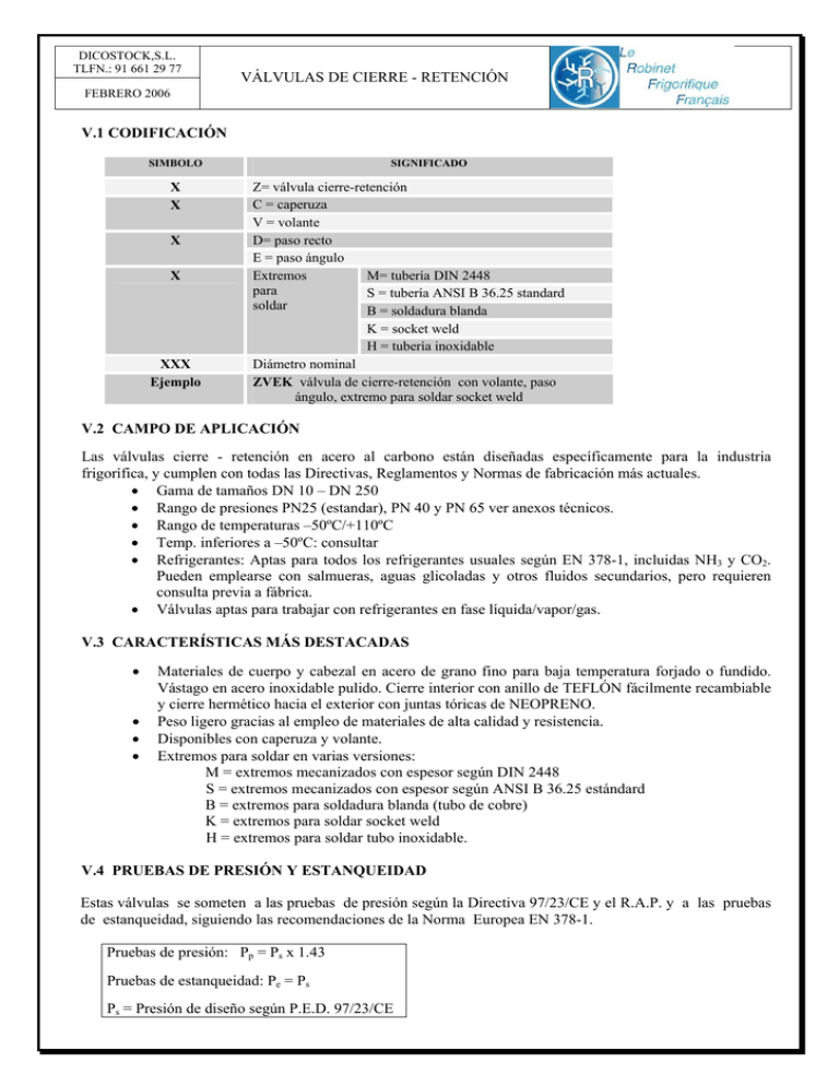
DICOSTOCK,S.L. TLFN.: 91 661 29 77 VÁLVULAS DE CIERRE - RETENCIÓN FEBRERO 2006 V.1 CODIFICACIÓN SIMBOLO X X X X XXX Ejemplo SIGNIFICADO Z= válvula cierre-retención C = caperuza V = volante D= paso recto E = paso ángulo Extremos M= tubería DIN 2448 para S = tubería ANSI B 36.25 standard soldar B = soldadura blanda K = socket weld H = tubería inoxidable Diámetro nominal ZVEK válvula de cierre-retención con volante, paso ángulo, extremo para soldar socket weld V.2 CAMPO DE APLICACIÓN Las válvulas cierre - retención en acero al carbono están diseñadas específicamente para la industria frigorífica, y cumplen con todas las Directivas, Reglamentos y Normas de fabricación más actuales. • Gama de tamaños DN 10 – DN 250 • Rango de presiones PN25 (estandar), PN 40 y PN 65 ver anexos técnicos. • Rango de temperaturas –50ºC/+110ºC • Temp. inferiores a –50ºC: consultar • Refrigerantes: Aptas para todos los refrigerantes usuales según EN 378-1, incluidas NH3 y CO2. Pueden emplearse con salmueras, aguas glicoladas y otros fluidos secundarios, pero requieren consulta previa a fábrica. • Válvulas aptas para trabajar con refrigerantes en fase líquida/vapor/gas. V.3 CARACTERÍSTICAS MÁS DESTACADAS • • • • Materiales de cuerpo y cabezal en acero de grano fino para baja temperatura forjado o fundido. Vástago en acero inoxidable pulido. Cierre interior con anillo de TEFLÓN fácilmente recambiable y cierre hermético hacia el exterior con juntas tóricas de NEOPRENO. Peso ligero gracias al empleo de materiales de alta calidad y resistencia. Disponibles con caperuza y volante. Extremos para soldar en varias versiones: M = extremos mecanizados con espesor según DIN 2448 S = extremos mecanizados con espesor según ANSI B 36.25 estándard B = extremos para soldadura blanda (tubo de cobre) K = extremos para soldar socket weld H = extremos para soldar tubo inoxidable. V.4 PRUEBAS DE PRESIÓN Y ESTANQUEIDAD Estas válvulas se someten a las pruebas de presión según la Directiva 97/23/CE y el R.A.P. y a las pruebas de estanqueidad, siguiendo las recomendaciones de la Norma Europea EN 378-1. Pruebas de presión: Pp = Ps x 1.43 Pruebas de estanqueidad: Pe = Ps Ps = Presión de diseño según P.E.D. 97/23/CE DICOSTOCK,S.L. TLFN.: 91 661 29 77 VÁLVULAS DE CIERRE - RETENCIÓN FEBRERO 2006 V.5 APROBACIONES Las válvulas y todos los productos RFF se fabrican con control de calidad ISO 9001. Bajo demanda se pueden suministrar con certificado de inspección de organismos de control como el TÜV, LLOYD´S y otros. V.6 DIRECTIVA DE APARATOS A PRESIÓN /REGLAMENTO ESPAÑOL DE APARATAOS A PRESIÓN Estas válvulas están homologadas para cumplir con la Directiva Europea de Aparatos a Presión CE 97/23 y con ello el Reglamento Español de Aparatos a Presión (RAP). Cumplen igualmente con el Reglamento Español de Instalaciones Frigoríficas (RSF). Llevan la marca CE. V.7 CARACTERÍSTICAS FÍSICAS DN PRESIÓN MÍNIMA DE APERTURA (Bar) 0.093 0.053 0.04 0.039 0.032 0.032 0.042 0.037 0.037 0.035 0.035 10/15 20/25 32/40 50 65 80 100 125 150 200 250 FUERZA DE APERTURA MÍNIMA (DaN) SUPERFICIE DE PASO (cm2) 0.3 0.49 0.86 1.6 2.2 2.9 6.2 6.5 11 16.35 25 2.54 6.157 15.9 23.76 38.48 55.42 88.24 134.78 188.69 277.59 422.73 V.8 MATERIALES DE CONSTRUCCIÓN 10 15 20 25 32 40 50 65 80 100 125 150 200 250 EXTREMOS S S S S S S S S S S S S S S M M M M M M M M M M M M M M H H H H H H H H H H H H H H B B B B B B B B B B - K K K K K - CUERPO CABEZAL CIERRE TstE355 TstE355 TstE355 TstE355 TstE355 TstE355 TstE355 GS21Mn5 GS21Mn5 GS21Mn5 GS21Mn5 GS21Mn5 GS21Mn5 GS21Mn5 TstE355 TstE355 TstE355 TstE355 TstE355 TstE355 TstE355 TstE355 TstE355 P355NL2 P355NL2 P355NL2 P355NL2 P355NL2 Teflón Teflón Teflón Teflón Teflón Teflón Neopreno Neopreno Neopreno Neopreno Teflón Teflón Teflón Teflón JUNTA DEL CUERPO Neopreno Neopreno Neopreno Neopreno Neopreno Neopreno Junta plana Junta plana Junta plana Junta plana Neopreno Neopreno Neopreno Neopreno VASTAGO X4CrNi14.3 DN DICOSTOCK,S.L. TLFN.: 91 661 29 77 VÁLVULAS DE CIERRE - RETENCIÓN FEBRERO 2006 V.9 DIMENSIONES DE VÁLVULAS DE CIERRE – RETENCIÓN PASO RECTO Y ÁNGULO DN 10 – DN 250 CON EXTREMOS PARA SOLDAR “S” CÓDIGO: ZVDS... CÓDIGO: ZCDS... CÓDIBO: ZVES... CÓDIGO: ZCES... 3/8 1 /2 3 /4 1 11/ 4 11/ 2 2 21/ 2 3” 4” 5” 6” 8” 10” DN 10 15 20 25 32 A* 128 128 161 161 200 B 25 25 33 33 40 C* 112 112 136 136 159 D 39 39 46 46 57 E 136 136 171 171 214 F 28 28 36 36 36 G 112 112 146 146 161 H 85 85 110 110 130 I 17.2 21.3 26.9 33.7 42.4 J 50 50 70 70 100 K 2.3 2.6 2.9 3.6 3.6 40 200 40 159 57 214 36 161 130 48.3 100 3.6 50 65# 247 305 41 49 209 235 69 85 257 308 36 41 206 237 152 200 60.3 76.1 125 175 4 5 80 100 125 150 200 250 360 397 545 569 833 946 54 58 66 71 88 106 273 85 368 50 281 238 88.9 200 5.6 299 105 396 50 299 275 114.4 200 6.3 427 120 558 50 442 308 139.7 250 7.1 435 135 584 48 450 344 168.3 250 701 655 170 869 56 691 427 219.1 400 8 723 215 945 56 722 527 273 400 9.3 DIMENSIONES EN MILIMETROS * Dimensiones con válvula abierta # DN 65 ref S065ZVDUSA, S065ZVEUSA, S065ZCDUSA o S065ZCE7SA ⇒ I=73, K=5.2 DICOSTOCK,S.L. TLFN.: 91 661 29 77 VÁLVULAS DE CIERRE - RETENCIÓN FEBRERO 2006 V.10 DIMENSIONES DE VÁLVULAS DE CIERRE – RETENCIÓN PASO RECTO Y ÁNGULO DN 10 – DN 250 CON EXTREMOS PARA SOLDAR “M” CÓDIGO: ZVDM... CÓDIGO: ZCDM... CÓDIBO: ZVEM... CÓDIGO: ZCEM... 3/8 1 /2 3 /4 1 11/4 11/2 2 21/2 3” 4” 5” 6” 8” 10” DN 10 15 20 25 32 40 50 65 80 100 125 150 200 250 A* 128 128 161 161 200 200 247 305 360 397 545 569 833 946 B 25 25 33 33 40 40 41 49 54 58 66 71 88 106 * Dimensiones con válvula abierta C* D E F G H 112 39 136 28 112 85 112 39 136 28 112 85 136 46 171 36 146 110 136 46 171 36 146 110 159 57 214 36 161 130 159 57 214 36 161 130 209 69 257 36 206 152 235 85 308 41 237 200 273 85 368 50 281 238 299 105 396 50 299 275 427 120 558 50 442 308 435 135 584 48 450 344 655 170 869 56 691 427 723 215 945 56 722 527 DIMENSIONES EN MILÍMETROS I 17.2 21.3 26.9 33.7 42.4 48.3 60.3 76.1 88.9 114.4 139.7 168.3 219.1 273 J 50 50 70 70 100 100 125 175 200 200 250 250 400 400 K 1.8 2 2.3 2.6 2.6 2.6 2.9 2.9 3.2 3.6 4.5 4.5 6.3 6.3 DICOSTOCK,S.L. TLFN.: 91 661 29 77 VÁLVULAS DE CIERRE - RETENCIÓN FEBRERO 2006 V.11 DIMENSIONES DE VÁLVULAS DE CIERRE – RETENCIÓN PASO RECTO Y ÁNGULO DN 10 – DN 100 CON EXTREMOS PARA SOLDAR “B” CÓDIGO: ZVDB... CÓDIGO: ZCDB... CÓDIBO: ZVEB... CÓDIGO: ZCEB... 1 /2 5/8 DN 10 15 A* 128 128 B 25 25 C* 112 112 7/8 11/8 13/8 15/8 21/8 25/8 31/8 41/8 20 25 32 40 50 65 80 100 161 161 200 200 247 305 360 397 33 33 40 40 41 49 54 58 136 46 171 36 146 110 136 46 171 36 146 110 159 57 214 36 161 130 159 57 214 36 161 130 209 69 257 36 206 152 235 85 308 41 237 200 273 85 368 50 281 238 299 105 396 50 299 275 DIMENSIONES EN MILÍMETROS * Dimensiones con válvula abierta D 39 39 E 136 136 F 28 28 G 112 112 H 85 85 J 50 50 O 12.9 16.1 70 70 100 100 125 175 200 200 22.4 28.8 35.2 41.5 54.3 66.9 79.6 105 P 12 15. 5 20 20 22 22 25 25 30 30 DICOSTOCK,S.L. TLFN.: 91 661 29 77 VÁLVULAS DE CIERRE - RETENCIÓN FEBRERO 2006 V.12 DIMENSIONES DE VÁLVULAS DE CIERRE – RETENCIÓN PASO RECTO Y ÁNGULO DN 10 – DN 32 CON EXTREMOS PARA SOLDAR “K” CÓDIGO: ZVDK... CÓDIGO: ZCDK... CÓDIBO: ZVEK... CÓDIGO: ZCEK... 3/8 1/2 3/4 1” 11/4 DN 10 15 20 25 32 A* 128 128 161 161 200 B 25 25 33 33 40 C* 112 112 136 136 159 * Dimensiones con válvula abierta D E F G H J 39 136 28 112 85 50 39 136 28 112 85 50 46 171 36 146 110 70 46 171 36 146 110 70 57 214 36 161 130 100 DIMENSIONES EN MILÍMETROS Q 17.5 21.9 27.4 34.1 42.9 R 10 10 13 13 13 S 7.2 5.1 9.3 5.9 5.3 DICOSTOCK,S.L. TLFN.: 91 661 29 77 VÁLVULAS DE CIERRE - RETENCIÓN FEBRERO 2006 V.13 DIMENSIONES DE VÁLVULAS DE CIERRE – RETENCIÓN PASO RECTO Y ÁNGULO DN 10 – DN 250 CON EXTREMOS PARA SOLDAR “H” CÓDIGO: ZVDH... CÓDIGO: ZCDH... CÓDIGO: ZVEH... CÓDIGO: ZCEH... DN 10 15 20 25 32 40 50 65 80 100 125 150 200 250 A* 128 128 161 161 200 200 247 305 360 397 545 569 833 946 B 25 25 33 33 40 40 41 49 54 58 66 71 88 106 C* D E F G H 3/8 112 39 136 28 112 85 1 /2 112 39 136 28 112 85 3 /4 136 46 171 36 146 110 1 136 46 171 36 146 110 11/4 159 57 214 36 161 130 11/2 159 57 214 36 161 130 2 209 69 257 36 206 152 21/2 235 85 308 41 237 200 3” 273 85 368 50 281 238 4” 299 105 396 50 299 275 5” 427 120 558 50 442 308 6” 435 135 584 48 450 344 8” 655 170 869 56 691 427 10” 723 215 945 56 722 527 DIMENSIONES EN MILÍMETROS * Dimensiones con válvula abierta I 17.2 21.3 26.9 33.7 42.4 48.3 60.3 76.1 88.9 114.4 139.7 168.3 219.1 273 J 50 50 70 70 100 100 125 175 200 200 250 250 400 400 K 2 2 2 2 2 2 2 2 2 2 2 2 2 2 DICOSTOCK,S.L. TLFN.: 91 661 29 77 VÁLVULAS DE CIERRE - RETENCIÓN FEBRERO 2006 V.14 RECOMENDACIONES SOBRE EL DIMENSIONADO DE LAS VÁLVULAS DE CIERRE – RETENCIÓN La correcta selección de las válvulas de retención en las tuberías de aspiración y descarga en los compresores, es una tarea no fácil y de mucha importancia: a) En tuberías de descarga En la descarga de los compresores el dimensionado debe de asegurar que la válvula no clapetea a cargas totales y parciales, y ello con una pérdida de presión a plena carga no superior aprox. a 0,2/0,3 bar, dependiendo del refrigerante y régimen de trabajo. b) En tubería de aspiración En las tuberías de aspiración la selección de la válvula de retención es aún más crítica que en la de descarga, pues en este caso, se debe de reducir la pérdida de presión para no sobrepasar las pérdidas equivalentes en grados ºK del orden de 0,2/0,4ºK y simultáneamente conseguir un funcionamiento estable. Es decir sin clapeteo, en todo el rango de regulación de capacidad del compresor, generalmente entre el 20% y 100%.
