RESUMEN Diseño del buje y de la estructura de soporte del
Anuncio
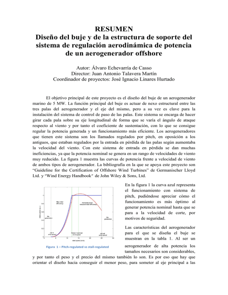
RESUMEN Diseño del buje y de la estructura de soporte del sistema de regulación aerodinámica de potencia de un aerogenerador offshore Autor: Álvaro Echevarría de Casso Director: Juan Antonio Talavera Martín Coordinador de proyectos: José Ignacio Linares Hurtado El objetivo principal de este proyecto es el diseño del buje de un aerogenerador marino de 5 MW. La función principal del buje es actuar de nexo estructural entre las tres palas del aerogenerador y el eje del mismo, pero a su vez es clave para la instalación del sistema de control de paso de las palas. Este sistema se encarga de hacer girar cada pala sobre su eje longitudinal de forma que se varía el ángulo de ataque respecto al viento y por tanto el coeficiente de sustentación, con lo que se consigue regular la potencia generada y un funcionamiento más eficiente. Los aerogeneradores que tienen este sistema son los llamados regulados por pitch, en oposición a los antiguos, que estaban regulados por la entrada en pérdida de las palas según aumentaba la velocidad del viento. Con este sistema de entrada en pérdida se dan muchas ineficiencias, ya que la potencia nominal se genera en un rango de velocidades de viento muy reducido. La figura 1 muestra las curvas de potencia frente a velocidad de viento de ambos tipos de aerogenerador. La bibliografía en la que se apoya este proyecto son “Guideline for the Certification of Offshore Wind Turbines” de Germanischer Lloyd Ltd. y “Wind Energy Handbook” de John Wiley & Sons, Ltd. En la figura 1 la curva azul representa el funcionamiento con sistema de pitch, pudiéndose apreciar cómo el funcionamiento es más óptimo al generar potencia nominal hasta que se para a la velocidad de corte, por motivos de seguridad. Las características del aerogenerador para el que se diseña el buje se muestran en la tabla 1. Al ser un aerogenerador de alta potencia los tamaños necesarios son considerables, y por tanto el peso y el precio del mismo también lo son. Es por eso que hay que orientar el diseño hacia conseguir el menor peso, para someter al eje principal a las Figura 1 – Pitch-regulated vs stall-regulated condiciones estáticas y de fatiga menos severas posibles y así alargar la vida útil del aerogenerador. Potencia nominal Profundidad de la cimentación marina Altura sobre el nivel del mar Longitud de las palas Velocidad nominal Vida útil Tabla 1 - Características generales del aerogenerador 5MW 50 m 100 m 30 m 12 rpm 25 años Para el inicio del diseño del buje se concibe este como la unión de tres bridas de conexión a pala y una al eje en un punto central. Por tanto se enfocó el inicio de los estudios estudiando cómo reaccionan dos bridas genéricas a esfuerzos en su cabeza de pernos. Se compararon dos diseños, la brida con paredes a 90 grados y la brida a 45 grados, realizando sobre ellos análisis de elementos finitos con el software CATIA V5R17, también usado para el modelado en 3D de todos los componentes. El objetivo es buscar una relación entre los espesores vertical y horizontal que optimice la distribución de esfuerzos en la estructura y extrapolarla a la estructura completa del buje. La brida que mejor respondió a los ensayos fue la brida recta, en la que sí se encontró un punto óptimo de relación de espesores. Tratando de trasladar los resultados de los estudios de las bridas al buje se inició el diseño de este, con una configuración recta, también con CATIA V5R17. Sin embargo, la conexión entre las bridas es muy brusca al ser estas rectas y en esas esquinas los esfuerzos que se obtenían por elementos finitos eran muy elevados, por lo que se ideó un segundo diseño en el que esa unión entre las bridas de conexión a las palas fuera menos brusca. Así se ideó el segundo diseño, de bridas con paredes a 60 grados, y se estudió por elementos finitos para comparar ambos diseños. Las figuras 2 y 3 muestran análisis por elementos finitos de ambas estructuras. Los esfuerzos utilizados son los proporcionados por el estudio del comportamiento aerodinámico del aerogenerador, realizado al mismo tiempo que este proyecto por un compañero del equipo que desarrolló el aerogenerador como proyecto conjunto. La estructura que mostró tensiones más bajas para las mismas configuraciones de espesores fue en todos los ensayos la de las bridas a 60 grados, por la menor brusquedad de las uniones, así que se continuó con este diseño. Figura 2 – Buje con bridas rectas Figura 3- Buje con bridas a 60 grados El sistema de control de paso se basa en un actuador eléctrico que engrana con la corona interna de un rodamiento de doble bola cuya parte fija está unida al buje, estando las palas unidas a la parte interna móvil de forma que pueden girar libremente respecto al buje. El rodamiento y el actuador de pitch vienen especificados por proyecto, por lo que habrá que diseñar el soporte que permita la instalación del sistema de forma que los dos elementos engranen perfectamente y aguante los esfuerzos que se derivarán del funcionamiento y los ciclos de cambio de gravedad. Al igual que con los dos tipos de buje, se idearon varias posibilidades para este soporte valorando las ventajas de cada uno y eligiendo en consecuencia. Debido al elevado número de ciclos, lo que manda para el diseño es el estudio a fatiga. El inconveniente de esto es que los análisis de fatiga son muy concretos para cada tipo de estructura, y es difícil encontrar datos sobre esto por lo que hay que generar una curva S/N de diseño (Incremento de tensión frente a número de ciclos). La normativa GL da las pautas para generar esta curva y que el análisis que se lleve a cabo sea aceptable según sus estándares de seguridad y diseño, que son los que se siguen en este proyecto. El material que se utiliza es fundición de grafito esferoidal, por sus óptimas características de absorción de vibraciones y comportamiento a fatiga, además de la necesidad de un material con alta fluidez para que la fundición se lleve a cabo de forma correcta y la calidad del buje sea la adecuada. Para el estudio a fatiga se utilizan las distintas situaciones de esfuerzos que se dan en un ciclo y que son proporcionadas por el estudio aerodinámico del proyecto ya mencionado antes. En un ciclo de funcionamiento normal se producen máximos y mínimos de tensión, y esa fluctuación mantenida en el tiempo es la que provoca el fallo por fatiga. Una vez determinada la curva de diseño se obtiene el incremento de tensión que la estructura puede soportar durante los ciclos estimados de funcionamiento de la turbina, y se revisa el diseño del buje para asegurar que cumple los requisitos. Como se esperaba, las severas condiciones hacen que el estudio por fatiga sea el predominante a la hora de diseñar, y hubo que modificar el peso del buje considerablemente para obtener espesores capaces de aguantarlas, siempre dentro de resultados de peso satisfactorios según la técnica actual. Figura 4 – Conjunto buje-sistema de control de paso de las palas ABSTRACT Design of the hub and the support structure for the aerodynamic power regulation system of an offshore wind turbine Author: Álvaro Echevarría de Casso Director: Juan Antonio Talavera Martín Project coordinator: José Ignacio Linares Hurtado The main goal of this Project is the design of the hub of an offshore 5 MW wind turbine. The hub functions as the structural link between the three blades and the main shaft, while it also provides support for the pitch control system. Such system makes the blades twist around their longitudinal axis, so the front angle of the blades is changed, and so is the lift coefficient, as the wind speed increases. This way, the turbine Figura 5 – Pitch-regulated vs stall-regulated generates its rated power for a wide range of wind speed, meaning a more efficient performance. Before this system was implemented, wind turbines were stall-regulated, which means that the blades were designed to stall as the wind speed rose, provoking a great deal of inefficiency, because the rated power is generated only in a very small range of wind speeds. The figure 1 shows the power curves as a function of the wind speed of both kinds of wind turbines. In the figure 1, the blue graph shows the performance of a pitch-controlled wind turbine. Comparing it to the red graph (stall- regulated), its greater efficiency can be appreciated, as it generates the rated power from the reference velocity to the cut wind speed. The main features of the wind turbine for which the hub is designed are shown in the table 1. Being a high power wind turbine, the sizes of the components are considerably large. Hence, the weight and stresses are large too. For it to be a profitable investment, the wind turbine must have a long life span, so the design must be oriented to achieving a light structure so the main shaft is subjected to as benign static and fatigue conditions as possible. Rated power Sea depth Hub height (over the sea level) Blade length Reference speed Life span Tabla 2 – Main features of the wind turbine 5MW 50 m 100 m 30 m 12 rpm 25 años To start the design of the hub, it is conceived as the union of three blade connection flanges and one shaft connection flange, stacked together in a center point. Therefore, they were studied separately, by designing two generic flanges: one with the walls in a 90 degree angle and another one in 45 degrees. These were designed and subjected to finite element analysis with the software CATIA V5R17. The goal is to find an optimum relationship between the vertical and the horizontal profile, so the stress distribution is the least severe for the structure, and afterwards to extrapolate the results to the entire hub structure. The flange which responded better was the one with 90 degree configuration, in which the Von Mises stresses were lower and an optimum relationship between thicknesses was found. Based on the results of the study of the flanges, a first hub was designed with 90 degree flanges. It was subjected to the aerodynamic forces obtained by a team mate, in charge of studying the aerodynamic behavior of the turbine. It was supposed to respond well to this forces but the abrupt connection between flanges provoked stress concentration on the corners. In order to solve this abrupt connection, another design was come up with, one with 60 degrees angle walls, so the connection between flanges is as smooth as possible. It turned out to respond better to the same forces than the 90 degree configuration, so it was chosen as the definitive configuration. Figures 2 and 3 show both hub configurations subjected to finite element analysis. Figure 6 – 90 degree flanges Figure 7- 60 degree flanges The pitch control system is based on an electric actuator driving a internal gear attached to a double row slewing ring. The blades are attached to the mobile part of the slewing ring while the fixed part is attached to the hub. Both the slewing ring and the actuator are given in the Project, so their compatibility must be assessed and a support that makes sure the function correctly must be designed. Following the same method as in the design of the hub, several models of this support were designed and compared. Due to the large number of cycles the wind turbine performs, the most severe conditions of a wind turbine are the fatigue conditions. This enters the difficulty of performing a fatigue analysis, which is a very specific study, characteristic of each structure and configuration. Thus, a S/N design curve must be generated (Stress range vs number of cycles). Germanischer and Lloyd’s “Guideline for the Certification of Offshore Wind Turbines” provides a guide to generate the curve following its safety and design standards, which are the ones that have been followed througout the whole project. The material used for the hub is ductile cast iron, an excellent material in terms of fatigue and vibrations, as well as for the casting process. The fatigue analysis is performed with the extreme Von Mises stresses in a cycle provided by the aerodynamic study already mentioned. That variation between the maximum and minimum value of the stress, prolonged through the years is what causes the fatigue failure. Once the curve is defined and the number of cycles is estimated, the hub and the support are reviewed to ensure the meet the requirements. As expected, thicknesses had to be increased to endure the fatigue conditions, so the weight of the structure had to be increased. Nevertheless, the final weight of the hub is satisfactory for the actual state of the art. Figure 4 shows a view of the hub and pitch control system set. Figure 8 – Hub + pitch control system set
