CARACTERISTICAS MAS IMPORTANTES:
Anuncio
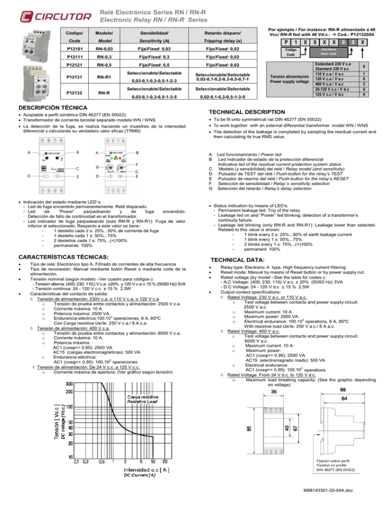
Relé Electrónico Series RN / RN-R Electronic Relay RN / RN-R Series Código/ Modelo/ Sensibilidad/ Retardo disparo/ Code Model Sensitivity (A) Tripping delay (s) P12101 RN-0,03 Fija/Fixed: 0,03 Fijo/Fixed: 0,02 P12111 RN-0,3 Fija/Fixed: 0,3 Fijo/Fixed: 0,02 P12121 RN-0,5 Fija/Fixed: 0,5 Fijo/Fixed: 0,02 Seleccionable/Selectable 0,03-0,1-0,3-0,5-1-2-3 Seleccionable/Selectable 0,02-0,1-0,2-0,3-0,5-0,7-1 Seleccionable/Selectable Seleccionable/Selectable 0,03-0,1-0,3-0,5-1-3-5 0,02-0,1-0,3-0,5-1-3-5 P12131 RN-R1 P12132 RN-R DESCRIPCIÓN TÉCNICA • Acoplable a perfil simétrico DIN 46277 (EN 50022) • Transformador de corriente toroidal separado modelo WN / WNS • La detección de la fuga, se realiza haciendo un muestreo de la intensidad diferencial y calculando su verdadero valor eficaz (TRMS) Por ejemplo / For instance: RN-R alimentado a 48 Vcc/ RN-R fed with 48 Vd.c.: Æ Cod.: P12132004 P 1 X X X X 0 0 X Cód.interno Intern. code Código Code Tensión alimentación Power supply voltage Estándard 230 V c.a Standard 230 V a.c 110 V c.a / V a.c 120 V c.a / V a.c 400 V c.a / V a.c 24-120 V c.c / V d.c 125 V c.c / V d.c 0 1 8 3 4 9 TECHNICAL DESCRIPTION • To be fit onto symmetrical rail DIN 46277 (EN 50022) • To work together with an external differential transformer model WN / WNS • The detection of the leakage is completed by sampling the residual current and then calculating its true RMS value. A B Led funcionamiento / Power led Led indicador de estado de la protección diferencial Indicative led of the residual current protection system status C Modelo (y sensibilidad) del relé / Relay model (and sensitivity) D Pulsador de TEST del relé / Push-button for the relay’s TEST E Pulsador de rearme del relé / Push-button for the relay’s RESET F Selección de sensibilidad / Relay´s sensitivity selection G Selección del retardo / Relay’s delay selection • Indicación del estado mediante LED´s: - Led de fuga encendido permanentemente: Relé disparado. - Led de “Power” parpadeando y de fuga encendido: Detección de fallo de continuidad en el transformador. - Led indicador de fuga parpadeando (solo RN-R y RN-R1): Fuga de valor inferior al seleccionado. Respecto a este valor se tiene: 1 destello cada 2 s: 25%...50% de corriente de fuga 1 destello cada 1 s: 50%...75% 2 destellos cada 1 s: 75%...(<)100% permanente: 100% CARACTERÍSTICAS TÉCNICAS: • • • • Tipo de relé: Electrónico tipo A. Filtrado de corrientes de alta frecuencia Tipo de reconexión: Manual mediante botón Reset o mediante corte de la alimentación. Tensión nominal (según modelo –Ver cuadro para códigos-): - Tensión alterna: (400; 230; 110;) V c.a. ±20% y 120 V c.a ± 15 % (50/60 Hz) 3VA - Tensión continua: 24 - 120 V c.c ± 15 % 2.5W Características del contacto de salida: ◊ Tensión de alimentación: 230V c.a. o 110 V c.a. o 120 V c.a o Tensión de prueba entre contactos y alimentación: 2500 V c.a. o Corriente máxima: 10 A. o Potencia máxima: 2500 VA. 3 o Endurancia eléctrica:100.10 operaciones, 6 A, 85ºC Con Carga resistiva Ue/Ie: 250 V c.a./ 8 A c.a. ◊ Tensión de alimentación: 400 V c.a. o Tensión de prueba entre contactos y alimentación: 6000 V c.a. o Corriente máxima: 10 A. o Potencia máxima: AC1 (cosφ<= 0,95): 2500 VA AC15 (cargas electromagnéticas): 500 VA o Endurancia eléctrica: 3 AC1 (cosφ<= 0,95): 100.10 operaciones ◊ Tensión de alimentación: De 24 V c.c. a 125 V c.c. o Corriente máxima de apertura: (Ver gráfico según tensión) • Status indication by means of LED’s: - Permanent leakage led: Trip of the relay. - Leakage led on and “Power” led blinking: detection of a transformer’s continuity failure. - Leakage led blinking (only RN-R and RN-R1): Leakage lower than selected. Related to this value is shown: 1 blink every 2 s: 25%...50% of earth leakage current 1 blink every 1 s: 50%...75% 2 blinks every 1 s: 75%...(<)100% permanent: 100% TECHNICAL DATA: • • • • Relay type: Electronic A type. High frequency current filtering Reset mode: Manual by means of Reset button or by power supply cut. Rated voltage (by model –See the table for codes-): - A.C Voltage: (400; 230; 110) V a.c. ± 20% (50/60 Hz) 3VA - D.C Voltage: 24 - 120 V d.c ± 15 % 2.5W Output contact specifications: ◊ Rated Voltage: 230 V a.c. or 110 V a.c. o Test voltage between contacts and power supply circuit: 2500 V a.c. o Maximum current: 10 A o Maximum power: 2500 VA. 3 o Electrical endurance: 100.10 operations, 6 A, 85ºC With resistive load Ue/Ie: 250 V a.c./ 8 A a.c. ◊ Rated Voltage: 400 V a.c. o Test voltage between contacts and power supply circuit: 6000 V a.c. o Maximum current: 10 A. o Maximum power: AC1 (cosφ<= 0,95): 2500 VA AC15 (electromagnetic loads): 500 VA o Electrical endurance: 3 AC1 (cosφ<= 0,95): 100.10 operations ◊ Rated Voltage: From 24 V d.c. to 120 V d.c. o Maximum load breaking capacity: (See the graphic depending on voltage) 5 6 7 8 1 2 3 4 Fijacion sobre perfil Fixation on profile DIN 46277 (EN 50022) M98143301-20-04A.doc Relé Electrónico Series RN / RN-R Electronic Relay RN / RN-R Series ESQUEMAS DE CONEXIÓN / CONNECTION DIAGRAM RN / RN-R + WN / WNS Sólo relés A.C / Only A.C relays Sólo relés A.C / Only A.C relays Sólo relés A.C / Only A.C relays Sólo relés A.C / Only A.C relays Sólo relés C.C / Only D.C relays Sólo relés C.C / Only D.C relays Vial Sant Jordi s/n 08232 Viladecavalls (Barcelona) SPAIN Tel: (+34) 93.745.29.00 Fax: (+34) 93.745.29.14 M98143301-20-04A.doc
