Utilitech 0362839 INSERT.indd
Anuncio
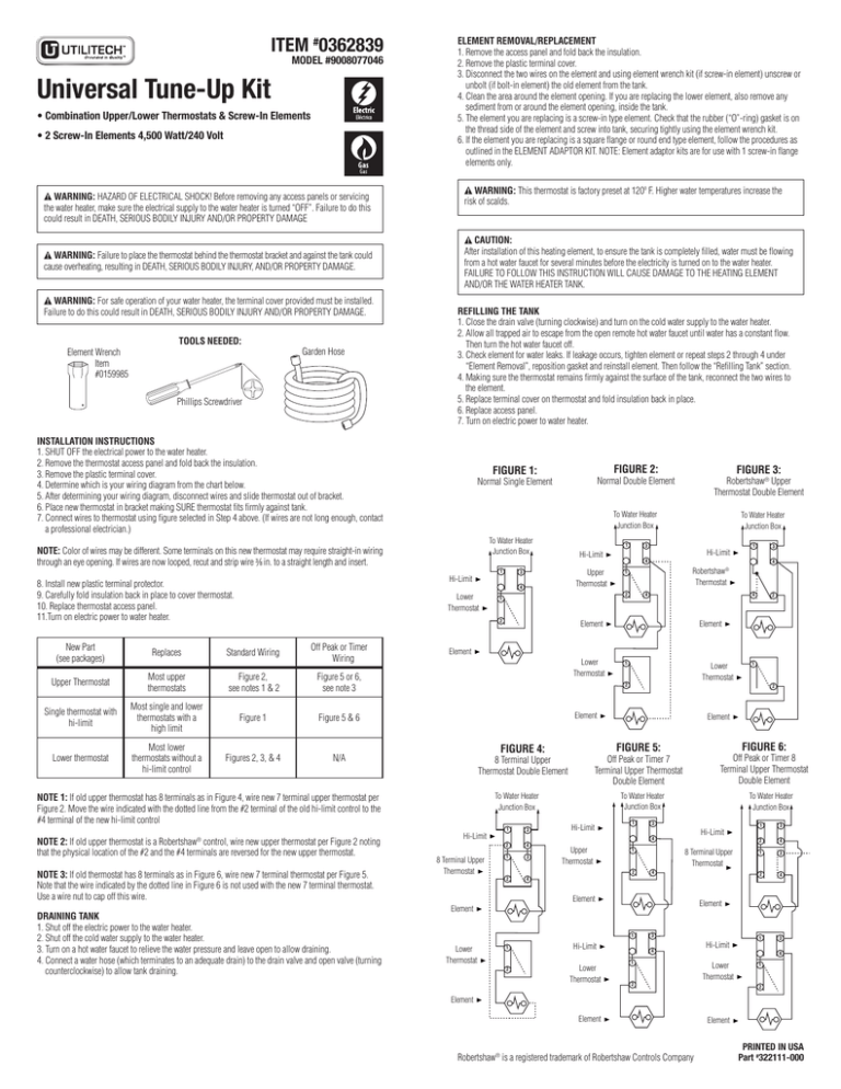
ITEM #0362839 MODEL #9008077046 Universal Tune-Up Kit • Combination Upper/Lower Thermostats & Screw-In Elements • 2 Screw-In Elements 4,500 Watt/240 Volt WARNING: HAZARD OF ELECTRICAL SHOCK! Before removing any access panels or servicing the water heater, make sure the electrical supply to the water heater is turned “OFF”. Failure to do this could result in DEATH, SERIOUS BODILY INJURY AND/OR PROPERTY DAMAGE WARNING: Failure to place the thermostat behind the thermostat bracket and against the tank could cause overheating, resulting in DEATH, SERIOUS BODILY INJURY, AND/OR PROPERTY DAMAGE. WARNING: For safe operation of your water heater, the terminal cover provided must be installed. Failure to do this could result in DEATH, SERIOUS BODILY INJURY AND/OR PROPERTY DAMAGE. Element Wrench Item #0159985 TOOLS NEEDED: Garden Hose Phillips Screwdriver ELEMENT REMOVAL/REPLACEMENT 1. Remove the access panel and fold back the insulation. 2. Remove the plastic terminal cover. 3. Disconnect the two wires on the element and using element wrench kit (if screw-in element) unscrew or unbolt (if bolt-in element) the old element from the tank. 4. Clean the area around the element opening. If you are replacing the lower element, also remove any sediment from or around the element opening, inside the tank. 5. The element you are replacing is a screw-in type element. Check that the rubber (“O”-ring) gasket is on the thread side of the element and screw into tank, securing tightly using the element wrench kit. 6. If the element you are replacing is a square flange or round end type element, follow the procedures as outlined in the ELEMENT ADAPTOR KIT. NOTE: Element adaptor kits are for use with 1 screw-in flange elements only. WARNING: This thermostat is factory preset at 120º F. Higher water temperatures increase the risk of scalds. CAUTION: After installation of this heating element, to ensure the tank is completely filled, water must be flowing from a hot water faucet for several minutes before the electricity is turned on to the water heater. FAILURE TO FOLLOW THIS INSTRUCTION WILL CAUSE DAMAGE TO THE HEATING ELEMENT AND/OR THE WATER HEATER TANK. REFILLING THE TANK 1. Close the drain valve (turning clockwise) and turn on the cold water supply to the water heater. 2. Allow all trapped air to escape from the open remote hot water faucet until water has a constant flow. Then turn the hot water faucet off. 3. Check element for water leaks. If leakage occurs, tighten element or repeat steps 2 through 4 under “Element Removal”, reposition gasket and reinstall element. Then follow the “Refilling Tank” section. 4. Making sure the thermostat remains firmly against the surface of the tank, reconnect the two wires to the element. 5. Replace terminal cover on thermostat and fold insulation back in place. 6. Replace access panel. 7. Turn on electric power to water heater. INSTALLATION INSTRUCTIONS 1.SHUT OFF the electrical power to the water heater. 2.Remove the thermostat access panel and fold back the insulation. 3.Remove the plastic terminal cover. 4.Determine which is your wiring diagram from the chart below. 5.After determining your wiring diagram, disconnect wires and slide thermostat out of bracket. 6.Place new thermostat in bracket making SURE thermostat fits firmly against tank. 7.Connect wires to thermostat using figure selected in Step 4 above. (If wires are not long enough, contact a professional electrician.) To Water Heater Junction Box 1 Hi-Limit 1 Upper Thermostat 3 Standard Wiring Off Peak or Timer Wiring Upper Thermostat Most upper thermostats Figure 2, see notes 1 & 2 Figure 5 or 6, see note 3 Single thermostat with hi-limit Most single and lower thermostats with a high limit Figure 1 Figure 5 & 6 Lower thermostat Most lower thermostats without a hi-limit control Figures 2, 3, & 4 N/A NOTE 3: If old thermostat has 8 terminals as in Figure 6, wire new 7 terminal thermostat per Figure 5. Note that the wire indicated by the dotted line in Figure 6 is not used with the new 7 terminal thermostat. Use a wire nut to cap off this wire. DRAINING TANK 1. Shut off the electric power to the water heater. 2. Shut off the cold water supply to the water heater. 3. Turn on a hot water faucet to relieve the water pressure and leave open to allow draining. 4. Connect a water hose (which terminates to an adequate drain) to the drain valve and open valve (turning counterclockwise) to allow tank draining. Hi-Limit 1 3 4 Robertshaw® Thermostat 1 4 4 Element 2 Element Element Lower Thermostat 1 Lower Thermostat 2 8 Terminal Upper Thermostat 1 3 To Water Heater Junction Box Hi-Limit 1 To Water Heater Junction Box 3 Hi-Limit 4 2 4 1 3 2 4 Upper Thermostat 1 2 8 Terminal Upper Thermostat 4 Element Element 1 2 Hi-Limit Lower Thermostat 1 3 2 4 1 3 2 4 Element 1 Lower Thermostat FIGURE 6: Off Peak or Timer 8 Terminal Upper Thermostat Double Element Off Peak or Timer 7 Terminal Upper Thermostat Double Element To Water Heater Junction Box Hi-Limit Element FIGURE 5: FIGURE 4: 8 Terminal Upper Thermostat Double Element 1 2 Element NOTE 1: If old upper thermostat has 8 terminals as in Figure 4, wire new 7 terminal upper thermostat per Figure 2. Move the wire indicated with the dotted line from the #2 terminal of the old hi-limit control to the #4 terminal of the new hi-limit control NOTE 2: If old upper thermostat is a Robertshaw® control, wire new upper thermostat per Figure 2 noting that the physical location of the #2 and the #4 terminals are reversed for the new upper thermostat. To Water Heater Junction Box 4 2 1 2 Replaces Robertshaw® Upper Thermostat Double Element 3 Hi-Limit 4 Lower Thermostat New Part (see packages) FIGURE 3: Normal Double Element To Water Heater Junction Box NOTE: Color of wires may be different. Some terminals on this new thermostat may require straight-in wiring through an eye opening. If wires are now looped, recut and strip wire 3/8 in. to a straight length and insert. 8.Install new plastic terminal protector. 9.Carefully fold insulation back in place to cover thermostat. 10. Replace thermostat access panel. 11.Turn on electric power to water heater. FIGURE 2: FIGURE 1: Normal Single Element 3 4 1 2 Hi-Limit 1 3 4 Lower Thermostat 1 2 Element Element Robertshaw® is a registered trademark of Robertshaw Controls Company Element PRINTED IN USA Part #322111-000 ARTÍCULO #0362839 MODELO #9008077046 Kit de afinamiento universal • Combinación de termostatos superior/inferior y elementos enroscables • Elementos enroscables de 4.500 vatios/240 voltios ADVERTENCIA: ¡PELIGRO DE DESCARGA ELÉCTRICA! Antes de retirar cualquier panel de acceso o de realizar servicio al calentador de agua, asegúrese de que se haya apagado el suministro eléctrico al calentador de agua. No hacerlo podría provocar LA MUERTE, GRAVES LESIONES CORPORALES Y/O DAÑO A LA PROPIEDAD ADVERTENCIA: No colocar el termostato detrás de la abrazadera del termostato y contra el tanque podría causar un sobrecalentamiento que provocaría LA MUERTE, graves lesiones personales Y/o daños A la propiedad. ADVERTENCIA: Para una operación segura del calentador de agua, se debe instalar la cubierta de terminales proporcionada. No hacerlo podría provocar LA MUERTE, GRAVES LESIONES CORPORALES Y/O DAÑO A LA PROPIEDAD. Llave para elemento #0159985 HERRAMIENTAS NECESARIAS: Manguera para jardín Destornillador Phillips INSTRUCCIONES DE INSTALACIÓN 1.DESCONECTE la alimentación eléctrica al calentador de agua. 2.Retire el panel de acceso al termostato y doble el aislamiento hacia atrás. 3.Retire la cubierta plástica de los terminales. 4.Determine cuál es su diagrama de cableado con la tabla que aparece a continuación. 5. Después de determinar el diagrama de cableado, desconecte los cales y deslice el termostato hacia afuera de la abrazadera. 6. Coloque el termostato nuevo en la abrazadera asegurándose de que éste calce firmemente contra el tanque. 7. Conecte los cables al termostato con la figura seleccionada en el paso 4 anterior. (Si los cables no son lo suficientemente largos, póngase en contacto con un electricista profesional). NOTA: El color de los cables puede ser distinto. Algunos terminales de este termostato nuevo pueden requerir un cableado recto a través de un orificio. Si los cables están en forma de anillo, vuelva a cortarlos y pele el cable 9,53 mm hasta un largo recto, luego insértelos. EXTRACCIÓN/REEMPLAZO DEL ELEMENTO 1. Retire el panel de acceso y doble el aislamiento hacia atrás. 2. Retire la cubierta plástica de los terminales. 3. Desconecte los dos cables del elemento enroscable y, con el kit de llaves para elementos, desatornille el elemento antiguo del tanque. 4. Limpie el área alrededor de la abertura del elemento. Si desea reemplazar el elemento inferior, también elimine todos los sedimentos de la abertura del elemento, dentro del tanque. 5. El elemento que desea reemplazar es un elemento de tipo enroscable. Verifique que la empaquetadura de goma (junta tórica) esté en el lado roscado del elemento y atorníllela al tanque, asegurándola firmemente con el kit de llaves para elementos. 6. Si el elemento que desea reemplazar es de tipo con brida cuadrada o de extremo redondo, siga los procedimientos como se describen en el KIT DE ADAPTADORES DE ELEMENTOS. NOTA: Los kits de adaptadores de elementos se deben usar sólo con elementos de brida enroscable de 1”. ADVERTENCIA: Este termostato está preajustado en fábrica a 48,9 grados C. Las temperaturas de agua más altas aumentan el riesgo de quemaduras. PRECAUCIÓN: Después de la instalación de este elemento de calentador, para asegurarse de que el tanque esté completamente lleno, el agua debe fluir desde un grifo de agua caliente por varios minutos antes de que se encienda la electricidad en el calentador de agua. EL INCUMPLIMIENTO DE ESTA INSTRUCCIÓN CAUSARÁ DAÑOS AL ELEMENTO DEL CALENTADOR Y/O AL TANQUE DEL CALENTADOR DE AGUA. RELLENADO DEL TANQUE 1. Cierre la válvula de drenaje (girando en dirección de las manecillas del reloj) y abra el suministro de agua fría del calentador de agua. 2. Permita que el aire atrapado se purgue del grifo de agua caliente remoto abierto hasta que el agua tenga un flujo constante. Luego cierre el grifo de agua caliente. 3. Verifique que el elemento no tenga fugas de agua. Si ocurren fugas, apriete el elemento o repita los pasos 2 a 4, bajo “Retiro del elemento”, vuelva a ubicar la empaquetadura y reinstale el elemento. Luego, siga la sección “Rellenado del tanque”. 4. Asegurándose de que el termostato permanezca firme contra la superficie del tanque, vuelva a conectar los dos cables al elemento. 5. Vuelva a colocar la cubierta de los terminales en el termostato y doble el aislamiento nuevamente a su ubicación. 6. Vuelva a colocar el panel de acceso. 7. Conecte la alimentación eléctrica al calentador de agua. Pieza nueva (consulte los empaques) Reemplaza Cableados estándar Cableado de bajo consumo o de temporizador Termostato superior La mayoría de los termostatos superiores Figura 2: Consulte las notas 1 y 2 Figura 5 o 6: Consulte la nota 3 Termostato simple con límite alto La mayoría de los termostatos simples e inferiores con límite alto Termostato inferior La mayoría de los termostatos inferiores sin control de límite alto Figura 1 Figuras 2, 3, y 4 Figura 5 y 6 To Water Heater Junction Box 1 Límite Alto Termostato Inferior Termostato Superior Elemento Doble Robertshaw® 3 Límite Alto 1 3 4 4 Termostato Superior Robertshaw® 1 2 1 To Water Heater Junction Box 4 4 Elemento 2 Elemento Elemento Termostato Inferior 1 Termostato Inferior 2 FIGURA 4: 1 2 Elemento Elemento FIGURA 5: FIGURA 6: Termostato Superior De 8 Terminales Bajo Consumo O Temporizador Termostato Superior De 7 Terminales Bajo Consumo O Temporizador Termostato Superior De 8 Terminales To Water Heater Junction Box To Water Heater Junction Box To Water Heater Junction Box Límite Alto Termostato Superior De 8 Terminales NOTA 2: Si el termostato superior antiguo es un control Robert Shaw®, cablee el termostato superior nuevo según la Figura 2, teniendo en cuenta que la ubicación física de los terminales #2 y #4 están al revés en el termostato superior nuevo. Elemento NOTA 3: Si el termostato antiguo tiene 8 terminales como en la Figura 6, cablee el nuevo termostato de 7 terminales según la Figura 5. Tenga en cuenta que el cable indicado con la línea punteada de la Figura 6 no se usa con el termostato de 7 terminales nuevo. Use un empalme plástico para tapar este cable. Termostato Inferior TANQUE DE DRENAJE 1. Desconecte la alimentación eléctrica del calentador de agua. 2. Corte el suministro de agua fría del calentador de agua. 3. Abra un grifo de agua caliente remoto para aliviar la presión del agua y déjelo abierto para permitir que se drene. 4. Conecte una manguera de agua (que termine en un drenaje adecuado) a la válvula de drenaje y abra la válvula (girando en dirección contraria a las manecillas del reloj) para permitir que el tanque se drene. 1 Límite Alto Termostato Superior 3 4 N/D NOTA 1: Si el termostato superior antiguo tiene 8 terminales como en la Figura 4, cablee el nuevo termostato superior de 7 terminales según la Figura 2. Mueva el cable indicado sin la línea punteada desde el terminal #2 del control de límite alto antiguo hasta el terminal #4 del control de límite alto nuevo FIGURA 3: Elemento Doble A La Caja De Unión Del Calentador De Agua 2 8. Instale el protector plástico de terminales. 9. Doble cuidadosamente el aislamiento nuevamente a su ubicación para cubrir el termostato. 10. Vuelva a colocar el panel de acceso al termostato. 11. Conecte la alimentación eléctrica al calentador de agua. FIGURA 2: FIGURA 1: Elemento Simple 1 3 Límite Alto 1 3 Límite Alto 4 2 4 1 3 2 4 Termostato Superior Termostato Superior De 8 Terminales 1 2 4 Elemento 2 Límite Alto Termostato Inferiort 3 4 1 3 2 4 Elemento 1 1 1 2 3 4 1 2 Límite Alto 1 3 4 Termostato Inferior 1 2 Elemento Elemento Robertshaw® es una marca registrada de Robertshaw Controls Company Elemento ADJETIVO EN EN EE.UU. Pieza #322111-000
