Descargar manual
Anuncio

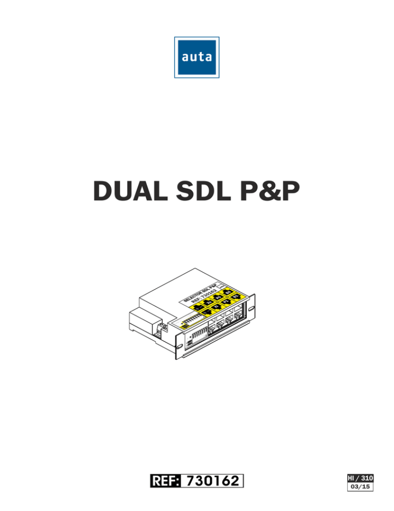
DUAL SDL P&P REF: 730162 HI / 310 03/15 DUAL SDL P&P DESCRIPTION - DESCRIPCIÓN El SDL (Selector Digital de Líneas) permite comunicar desde varios accesos comunes exteriores con uno de los edificios interiores, con el fin de no afectar al resto de edificios, que pueden mantener su comunicación de forma simultánea e independiente. Cada uno de los edificios interiores, puede direccionar un máximo de 254 viviendas y disponer hasta de 15 accesos independientes. Por tanto, mediante el SDL podemos comunicar desde los accesos exteriores hasta con 254 chalets o viviendas adosadas, con 254 edificios de 254 apartamentos cada uno, o una combinación de ambos. CARACTERISTICAS El DUAL SDL implementa dos SDL con conectividad CAT5 según la Norma T568B. Sus dimensiones (1U x 2U x 3U) y diseño mecánico permiten la instalación en rack normalizado, fijado a la pared o en carril DIN (opcional). Dispone de: - Una entrada RJ45 de bus X, procedente de otro DUAL SDL o una placa de calle exterior. - Una salida RJ45 de bus X, para conectar con otro DUAL SDL. - Dos entradas RJ45 de placa de calle interior (una por cada SDL simple). - Dos salidas RJ45 para bajante de edificio (una por cada SDL simple). - Entrada de alimentación local de 24Vdc. - Dos salidas RJ45 de alimentación de 24 Vdc (para las placas interiores). - Led indicador. - Switch y jumpers de configuración. The SDL (Digital Lines Selector) allows communication from several common entrances to one of the inner buildings, in order to not affect other buildings. Those can keep their communication simultaneously and independently. Each of the inner buildings, can address up to 254 homes and have up to 15 separate entrances. Therefore, using the SDL we can communicate from the external access to 254 townhouses and chalets, 254 buildings with 254 apartments each, or a combination of both. FEATURES The DUAL SDL implements two SDL with CAT5 connectivity according to the T568B standard. Dimensions (1U x 2U x 3U) and mechanical design allows installation in standard rack, fixed to the wall or DIN rail (optional). Consists of: - One RJ45 bus X input, from another DUAL SDL or external street panel. - One RJ45 bus X output to connect to other DUAL SDL. - Two RJ45 inputs for inner entrance panel (one per each single SDL). - Two RJ45 outputs for building riser (one per each single SDL). - Input for local power (24 Vdc). - Two RJ45 power (24 Vdc) outputs (for the inner panels). - Indicator led. - Configuration switch and jumpers. DIMENSIONS - DIMENSIONES 92 133 110.8 42 LED L0 L1 1 2 3 4 5 6 7 8 ON DUAL SDL P&P DESCRIPTION - DESCRIPCIÓN CHAPA DE SUJECCIÓN PARA: BRACKET FOR: - RACKS(3U x 1U) POWER SUPPLY ALIMENTACIÓN LED SELECTOR SDL P&P L0: ON/OFF L1: ON/OFF 0 1 CODIGO SDL SDL CODE Xo P0 B0 Xi P1 B1 LED L0 L1 JUMPERS PULL-UP 1 2 3 4 5 6 7 8 - PARED-WALL ON SWITCH CONFIGURACIÓN ALIMENTACION Bornas de alimentación para conectar una fuente de 24 Vdc, para alimentar al DUAL SDL y las placas conectadas a las salidas Power0 y Power1. JUMPERS PULL-UP Cuando no se instale placa interior en alguna de las partes del DUAL SDL (0 y 1), se deberá conectar su resistencia de Pull-Up mediante el jumper correspondiente. Izquierda ON. Derecha OFF LED Indica si alguno de los dos SDL incluidos en el DUAL SDL está activo. Verde=SDL 0 ; Rojo=SDL 1 SWITCH DE CONFIGURACION Define el código de llamada del SDL0. ATENCION: Para evitar códigos de llamada duplicados, el SWITCH1 debe estar siempre ARRIBA. POWER0 Y POWER1 Salidas para alimentar los módulos de control de las placas interiores de cada SDL. Xin Entrada de bus exterior. Xout Salida de bus exterior. P0 Y P1 Entradas de buses de placas interiores. B0 Y B1 Salidas de buses de bajantes interiores. POWER SUPPLY Terminals for connecting a 24 Vdc power supply, to power the DUAL SDL and the panels connected to Power0 y Power1 outputs. PULL-UP JUMPERS When there is not installed an inner panel at any of the parts of the DUAL SDL (0 and 1), it is required to connect its Pull-Up resistor with the corresponding jumper. LEFT ON. RIGHT OFF LED Indicates if any of the two embeded SDL in the DUAL SDL is active. Green=SDL 0 ; Red=SDL 1 CONFIGURATION SWITCH Defines the calling code of SDL0. WARNING: To avoid duplicated calling codes, SWITCH1 must be allways UP. POWER0 and POWER1 Outputs to power the modules of control of the inner panels of each SDL. Xin External bus input. Xout External bus output. P0 AND P1 Inner panels busses inputs. B0 AND B1 Inner risers busses outputs. DUAL SDL P&P CONNECTIVITY - CONECTIVIDAD La conectividad de las entradas y salidas de señal (Xin, Xout, P0, P1, B0, B1) se realiza con conectores RJ-45 siguiendo la norma T568B, con la siguiente asignación de señales: The connectivity of the signal inputs and outputs (Xin, Xout, P0, P1, B0, B1) is performed with RJ-45 connectors following the T568B standard, with the following signal assignment: 1 2 3 4 5 6 7 8 Naranja/Blanco Naranja Verde/Blanco Azul Azul/Blanco Verde Marrón/Blanco Marrón Positivo (+24Vdc) Positivo (+24Vdc) Negativo Va Vb Negativo Altavoz Micrófono 1 2 3 4 5 6 7 8 Orange/White Orange Green/White Blue Blue/White Green Brown/White Brown Positive (+24Vdc) Positive (+24Vdc) Negative Va Vb Negative Speaker Microphone La conectividad de las salidas de alimentación (POWER0 y POWER1) también se realiza con conectores RJ-45 siguiendo la norma T568B, pero con la siguiente asignación de pines: The connectivity of the power outputs (POWER0 and POWER1) are also performed with RJ-45 connectors following the T568B standard, but with the following pin assignment: 1 2 3 4 5 6 7 8 Naranja/Blanco Naranja Verde/Blanco Azul Azul/Blanco Verde Marrón/Blanco Marrón Positivo (+24Vdc) Positivo (+24Vdc) Negativo Negativo Negativo Negativo Positivo (+24Vdc) Positivo (+24Vdc) 1 2 3 4 5 6 7 8 Orange/White Orange Green/White lue Blue/White Green Brown/White Brown Positive (+24Vdc) Positive (+24Vdc) Negative Negative Negative Negative Positive (+24Vdc) Positive (+24Vdc) 1 MUY IMPORTANTE Despues de montar los conectores RJ-45, verificar cada cable utilizando el “RJ-45 TESTER KIT” (REF: 730157) VERY IMPORTANT After assembling the RJ-45 connectores, check each cable using the “RJ-45 TESTER KIT” (REF: 730157) 1 2 3 4 5 6 7 8 DUAL SDL P&P ESQUEMA - SCHEMA SALIDA BUS EXTERIOR EXTERNAL BUS OUTPUT ALIMENTACIÓN POWER SUPPLY CAT 5 (T568B) SOLO CODIGOS PARES ONLY PAIR CODES 2 SELECTOR SDL P&P ALV-2.5A L0: ON/OFF L1: ON/OFF 0 1 CODIGO SDL SDL CODE Xo P0 B0 Xi P1 B1 LED 230 Vac L0 L1 1 2 3 4 5 6 7 8 ON 2 ENTRADA BUS EXTERIOR EXTERNAL BUS INPUT CAT 5 (T568B) CAT 5 (T568B) CAT 5 (T568B) BUS DE BAJANTE INTERIOR INNER RISER BUS CAT 5 (T568B) PLACA INTERIOR INNER PANEL POL. IND. EL OLIVERAL - CALLE C , NAVES 9-10 46394 RIBARROJA DEL TURIA (VALENCIA) TFNO. +34 96 164 30 20 - FAX. +34 96 166 52 86 E-MAIL: [email protected] HTTP://WWW.AUTA.ES

