wireless wall receiver bt-wr02 rf
Anuncio
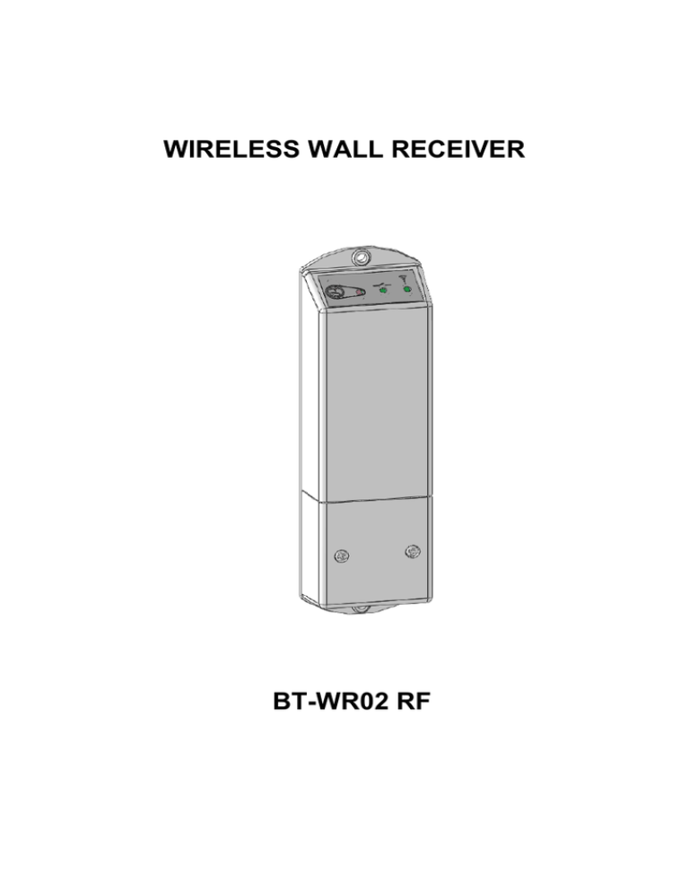
WIRELESS WALL RECEIVER BT-WR02 RF 1 2 USER GUIDE BT-WR02 RF Wall Receiver GB 4-5 GUIDE D’UTILISATION BT-WR02 RF Récepteur mural FR 6-7 BEDIENUNGSANLEITUNG Wandempfänger BT-WR02 RF D 8-9 GUIA DE USUARIO Receptor mural BT-WR02 RF ES 10-11 BRUKSANVISNING BT-WR02 RF-väggmottagare SE 12-13 Installation sheet 14-16 3 GB BT-WR02 RF Wall Receiver 1. Presentation The BT-WR02 RF receiver is a Wall mounting receiver, specially designed to control electrical floor heating regulation in combination or not with a wireless thermostat BT-DP02 RF. This couple (Thermostat Receiver) can also be managed by a Central to have full control of your heating installation from one point. A A (RF configuration button ) / Short press 3sec press 6sec press B C B (Green/Red) C (red) D (green) / / / / / / / green green green orange orange blinking green green orange red / / / green / / / Green flash Green Green blinking / Green flash / Permanently Green blinking 15sec press 2. / D Power ON Instantaneous RF transmission Thermostat or Central RF init. Slave receiver RF init. Reset of the receiver Heating demand RF reception Pilot wire information RF Alarm Technical characteristics Environment. (Temperatures) Operating : shipping et storage : Power supply Electrical protection Pilot wire Input (French market) Output Maximum Load Radio Frequency & RF Receiving distance CE Directives Your product has been designed in conformity with the European Directives. 0°C - 40°C -10°C to +50°C 230Vac 50Hz Class II - IP20 6 orders Pilot Wire by phase (L) Relay 10Amps 250VAC Up to 10A - 250Vac 50Hz (2 wires L,N) 868MHz < 10mW (Bidirectional communication) Range of approximately 100m in open space. Range of approximately 30m in residential environment. R&TTE 1999/5/EC LVD 2006/95/EC EMC 2004/108/EC RoHS 2011/65/EU 4 3. Installation and RF Initialisation rules Install and plug the receiver into the following guidelines to guaranty an optimal reception: The receiver must be put at a minimum distance of 50cm of all others electrical or wireless materials like GSM, Wi-Fi router. Before wiring work related to the receiver must be carried out only when de-energized Connect your receiver to the power supply. Following your installation an order of pairing must be respected for a correct RF initialisation. Installation 1: Receiver + RF thermostat 1. The receiver must be put in RF init mode by 5sec pressing on the RF Button. 2. Then the RF LED should be Green fixed indicating that the Receiver is now in radio configuration mode waiting for a thermostat configuration address. 3. Please refer to the thermostat leaflet for enter the thermostat in “RF Init” mode. 4. The receiver RF LED must be switched OFF and the thermostat should exit the RF init mode to indicate correct paring between both elements. Installation 2: Receiver + RF Thermostat + RF Central 1. Make the “Installation 1” rules for pairing with the thermostat. 2. The receiver must be put one time more in RF init mode by 5sec pressing on the RF Button. 3. Then the RF LED should be Green fixed indicating that the Receiver is now in radio configuration mode waiting for a thermostat configuration address. 4. Please refer to the Central leaflet for more explanation about the pairing mode “RF Init”. 5. The receiver RF LED must be switched OFF and the Central will show a message to indicate correct paring between both elements. Installation 3: Receiver + RF Thermostat + RF Central + Slave receiver(s) 1. Make the “Installation 2” rules for pairing with the thermostat and the Central. 2. The Master receiver (receiver paired with the thermostat & Central) must be put in Receiver RF init mode by 10sec pressing on the RF Button. 3. Then the RF LED should be Green/Red fixed indicating that the Receiver is now in radio configuration mode waiting for a thermostat configuration address. 4. Put now the Slave receiver in RF init mode by 5sec pressing on the RF button. 5. The Master and Slave receiver RF LED must be switched OFF to indicate correct paring between both elements. 6. You can link up to 3 Slave receivers on a Master receiver, for this repeat the step 2 to 5 for each slave. Note: - In case of installation with Pilot Wire, all receiver linked together (Master + slave) must be connected to the same Pilot wire zone. Installation 4: Receiver + Central 1. The receiver must be put in RF init mode by 5sec pressing on the RF Button. 2. Then the RF LED should be Green fixed indicating that the Receiver is now in radio configuration mode waiting for a Central configuration address. 3. Please refer to the Central leaflet for more explanation about the pairing mode “RF Init”. 4. The receiver RF LED must be switched OFF and the Central will show a message to indicate correct paring between both elements. Remarks: The BT-WR02 RF receiver can be linked with a BT-PR02 RF or BT-FR02 RF receivers as slaves unit. In case of loss RF communication (RF Alarm), the receiver will follow 20% cycle of heating to prevent the installation against frost. (The receiver will stay in OFF mode if it was in OFF before loss of RF communication). The LEDs are turned off from 8pm to 8am; a short press on the RFkey reactive the LEDs for a short time 5 BT-WR02 RF Récepteur mural FR 1. Presentation Le récepteur BT-WR02 RF est un récepteur mural spécialement conçu pour contrôler la régulation de système de chauffage électrique (Chauffage par le sol ou radiateur en combinaison ou non avec un thermostat BT-DP02 RF) Ce couple (thermostat récepteur) pourra être géré par une centrale pour avoir le contrôle total de votre installation de chauffage d’un même endroit. A A (Bouton de configuration RF) / Appui court B C D B (Rouge/vert) C (Rouge) D (Vert) Vert Vert / / Alimenté Transmission RF instantanée Appui de 3 sec Vert / Appui de 6 sec / / Vert clignotant réinitialisation du récepteur. (effacement des codes) / orange orange blinking Vert / / Vert clignotant rapide Vert Rouge Demande de chauffe / Vert / / orange / / Vert / / Vert clignotant rapide / Permanently Vert blinking Appui de 15 sec 2. initialisation RF du thermostat ou de la centrale. initialisation RF du récepteur esclave Réception RF Signal sur le Fil pilote Alarme RF Caractéristiques techniques Environnement. (Températures) Fonctionnement: Transport et stockage : Alimentation Protection électrique Entrée fil pilote (marché français) Sortie Charge maximale Radio Fréquence & Distance de réception Directives CE Votre produit a été conçu en conformité avec les directives européennes : 0°C - 40°C -10°C à +50°C 230Vac 50Hz Classe II - IP20 Fil pilote 6 ordres par phase (L) Relais 10Amps 250VAC Jusqu’à 10A - 250Vac 50Hz (2 fils L,N) 868MHz < 10mW (communication bidirectionnelle) Environ 100m en milieu ouvert Environ 30m in environnement résidentiel R&TTE 1999/5/EC Basse Tension 2006/95/EC CEM 2004/108/EC RoHS 2011/65/EU 6 3. Installation et initialisation RF Installez et branchez le récepteur suivant les instructions ci-dessous pour garantir une réception optimale : Le récepteur doit être placé à une distance minimale de 50 cm de tout appareil électrique ou matériel sans fil comme les GSM, routeur Wi-Fi Les travaux de câblage liés au récepteur doivent uniquement être faits hors tension Branchez votre récepteur Suivant votre installation, un ordre d’appairage doit être respecté pour avoir une initialisation RF correcte. Installation 1: récepteur + thermostat RF 1. Le récepteur doit être en mode “RF init” en appuyant pendant 5 secondes sur le bouton RF. 2. La LED RF s’allume en vert indiquant que le récepteur est désormais en mode de configuration RF en attente d’une adresse de configuration d’un thermostat. 3. Se référer à la notice du thermostat pour le mettre en mode « RF Init » 4. La LED du récepteur doit s’éteindre et le thermostat doit quitter le mode RF Init pour indiquer que l’appairage s’est correctement déroulé. Installation 2: récepteur + thermostat RF + Centrale RF 1. Suivre les instructions de « l’installation 1 » pour l’appairage avec le thermostat 2. Le récepteur doit être placé une nouvelle fois en mode « RF Init » en appuyant 5 secondes sur le bouton RF 3. La LED RF s’allume en vert indiquant que le récepteur est désormais en mode de configuration RF en attente d’une adresse de configuration d’un thermostat. 4. Se référer à la notice de la centrale pour plus d’explications sur le mode d’appairage « RF Init » 5. La LED du récepteur doit s’éteindre et la centrale affiche un message pour indiquer que l’appairage est correct entre les deux éléments Installation 3: récepteur + thermostat RF + Centrale RF + récepteur(s) esclaves 1. Suivre les instructions de « l’installation 2 » pour l’appairage avec le thermostat et la centrale 2. Le récepteur « maître » (récepteur appairé avec le thermostat et la centrale) doit être placé en mode Rf Init en appuyant 10 secondes sur le bouton RF 3. La LED RF doit être allumée en vert/rouge indiquant que le récepteur est en mode de configuration radio en attente d’une adresse de configuration d’un thermostat. 4. Maintenant mettre le récepteur esclave en mode RF Init en appuyant 5 secondes sur le bouton RF. 5. Les LED RF des récepteurs maître et esclave doivent alors s’éteindre pour indiquer que l’appairage est correct entre les deux éléments 6. Vous pouvez lier jusqu’à 3 récepteurs esclaves par récepteur maître. Pour cela, répétez les étapes 2 à 5 pour chaque esclave Note: - Dans le cas d’une installation avec fil pilote, tous les récepteurs liés ensemble (maître + esclave) doivent être connectés sur la même zone de fil pilote. Installation 4: Récepteur + Centrale 1. Le récepteur doit être place en mode “RF init” en appuyant pendant 5 secondes sur le bouton RF. 2. La LED RF s’allume en vert indiquant que le récepteur est désormais en mode de configuration RF en attente d’une adresse de configuration de la centrale. 3. Se référer à la notice de la centrale pour plus d’explications sur le mode d’appairage « RF Init » 4. La LED du récepteur doit s’éteindre et la centrale affiche un message pour indiquer que l’appairage est correct entre les deux éléments Remarques: Le récepteur BT-WR02 RF peut être lié à des récepteurs BT-DP02 RF ou BT-FR02 RF en tant qu’unité esclave. En cas de perte de communication RF (alarme RF), le récepteur suivra un cycle de 20% de chauffe pour protéger votre installation contre le gel. (le récepteur restera en mode OFF s’il était en mode OFF avant la perte de communication RF) Les LEDs sont éteintes de 20h à 8h ; un appui court sur la touche « RF » réactive les leds pendant un court instant 7 D BT-WR02 RF Wandempfänger 1. Beschreibung BT-WR02 RF drahtloser Empfänger für Montage auf die Installationsdose KU 68, zur Regelung der elektrischen Heizung und Fußbodenheizung in Kombination mit dem drahtlosen Thermostat Typ BT-DP02 RF oder direkt mit der Zentraleinheit bestimmt. Thermostat + Empfänger - es kann von der Zentraleinheit gesteuert werden, wodurch komplette Bedienung des Heizsystems aus einer Stelle gesichert ist. A A(RF Konfigurationstaste) / Kurze Betätigung Betätigung für 3 Sekunden Betätigung für 6 Sekunden Betätigung für 15 Sekunden / B (Grün/Rot) Grün Grün C (Rot) / / Grün / Orange / Grün Orange Blinkt / Grün Blinkt / schnell blinkt grün / Blinkt (regemäßig) Grün Rot / Grün / / Orange / / Grün / 2. B D (Grün) / / schnell blinkt grün C D Angetrieben sofortige RF-Übertragung Paarung des Thermostates/der Zentraleinheit Paarung des abhängigen Empfängers Zurücksetzen des Empfängers Heizung eingeschaltet RF Empfang Information des Pilotleiters RF Alarm Technische Charakteristik Betriebstemperatur: Transport und Lagerung: Speisung: Elektrischer Schutz: Eingang für Pilotleiter (französischer Markt): Ausgang: Höchstbelastung: Radiofrequenz & Abstand für RF-Empfang: 0°C - 40°C von -10°C bis +50°C 230 Vac 50Hz Klasse II – IP 20 Pilotleiter - 6 Befehle (Phase (L) ) Relais 10A 250 VAC Bis 10A – 250Vac 50Hz (2 Leiter L, N) 868 MHz < 10mW (bidirektionale Kommunikation) Reichweite von ca. 100m in freiem Raum. Reichweite von ca. 30m in bewohnten Orten R&TTE 1999/5/EC LVD 2006/95/EC EMC 2004/108/EC RoHS 2011/65/EU CE-Richtlinien Ihr Produkt wurde in Übereinstimmung mit den EURichtlinien konzipiert. 8 3. Regel für Installierung und Initialisierung der Radiofrequenz Zwecks optimalen Empfangs ist der Empfänger nach den folgenden Anweisungen zu installieren und anzuschließen. Der Empfänger ist immer im Abstand von mindestens 50 cm von anderen elektrischen und drahtlosen Einrichtungen, z.B. GSM, Wi-Fi Router zu installieren. Vor Beginn der Elektroinstallationsarbeiten am Empfänger ist der Kraftstromkreis (Speisekreis) des Empfängers zu trennen – er muss ohne Spannung sein. Den Empfänger zur Spannungsquelle anschließen. Wegen richtiger Initialisierung der Radiofrequenz ist es nach der Installation nötig, das folgende Paarungsvorgehen gemäß dem Einrichtungstyp einzuhalten. Kombination 1: 1. 2. 3. 4. Mit Betätigung der Taste RF für 5 Sekunden den Empfänger in das Regime RF init schalten. Die RF LED leuchtet grün – der Empfänger befindet sich im Regime Konfiguration der Radiokommunikation und wartet auf Konfigurationsbefehl des Thermostates. Nach den Bedienungsanweisungen des Thermostates vorgehen – Regime des Thermostats „RF Init“. Ausschaltung der RF LED des Empfängers und Austritt des Thermostats aus dem Regime RF signalisiert richtige Paarung von beiden Elementen. Kombination 2: 1. 2. 3. 4. 5. 2. 3. 4. 5. 6. Empfänger + RF Thermostat + RF Zentraleinheit Die im Teil „Kombination 1“ angeführten Anweisungen zur Paarung mit dem Thermostat durchführen. Mit Betätigung der Taste RF für 5 Sekunden den Empfänger in das Regime RF init schalten. Die RF LED leuchtet grün – der Empfänger befindet sich im Regime Konfiguration der Radiokommunikation und wartet auf Konfigurationsbefehl der Zentraleinheit. Nach den Bedienungsanweisungen der Zentraleinheit vorgehen – Regime der Paarung „RF Init“. Die RF LED des Empfängers SCHALTET SICH AUS und die Zentraleinheit zeigt die Meldung an, dass beide Elemente richtig gepaart wurden. Kombination 3: 1. Empfänger – RF Thermostat Empfänger + RF Thermostat +RF Zentraleinheit + abhängiger Empfänger/abhängige Empfänger Die im Teil „Kombination 2“ angeführten Anweisungen zur Paarung mit dem Thermostat und der Zentraleinheit durchführen. Mit Betätigung der Taste RF für 5 Sekunden den Hauptempfänger (den mit dem Thermostat und der Zentraleinheit gepaarten Empfänger) in das Regime des Empfängers RF init schalten. Die RF LED leuchtet grün/rot – der Empfänger befindet sich im Regime der Konfiguration der Radiokommunikation und wartet auf Konfigurationsbefehl des abhängigen Empfängers. Mit Betätigung der Taste RF für 5 Sekunden den abhängigen Empfänger in das Regime RF init schalten. Die RF LED des Hauptempfängers und des abhängigen Empfängers SCHALTET SICH AUS, was richtige Paarung von beiden Elementen signalisiert. An den Hauptempfänger können bis 3 abhängige Empfänger angeschlossen werden, für jeden abhängigen Empfänger sind die Schritte 2 bis 5 zu wiederholen. Bemerkung Bei Einrichtungen mit Pilotleiter müssen alle Empfänger, die miteinander verbunden sind (Hauptempfänger + abhängige Empfänger), zu derselben Zone des Pilotleiters angeschlossen sein. Kombination 4: 1. 2. 3. 4. Empfänger + Zentraleinheit Mit Betätigung der Taste RF für 5 Sekunden den Empfänger in das Regime RF init schalten. Die RF LED leuchtet grün – der Empfänger befindet sich im Regime der Radiokonfiguration und wartet auf Konfigurationsbefehl der Zentraleinheit Nach den Bedienungsanweisungen der Zentraleinheit vorgehen – Regime der Paarung „RF Init“. Die RF LED des Empfängers SCHALTET SICH AUS und die Zentraleinheit zeigt die Meldung an, dass beide Einheiten richtig gepaart sind. Bemerkung: Der Empfänger BT-WR02 RF kann mit den Empfängern BT-DP02 RF oder BT-FR02 RF als abhängigen Einheiten gepaart werden. Beim Verlust der RF Kommunikation (RF Alarm) erhält der Empfänger 20% des Heizzyklus um Einfrieren der Einrichtung zu verhindern. Der Empfänger bleibt im Regime AUSGESCHALTET, falls er vom Thermostat oder von der Zentraleinheit in das Regime AUSGESCHALTET noch vor dem Verlust der RF Kommunikation gebracht wurde. LEDs sind aus von 20h bis 8h, ein kurzer Druck auf die Taste "RF" reaktiviert LEDs für ein kurze Zeit 9 BT-WR02 RF Receptor mural ES 1. Descripción BT-WR02 RF receptor sin hilos para el montaje en la caja de instalación KU 68, destinado a la regulación de la calefacción eléctrica y a la calefacción de suelo en combinación con el termóstato sin hilos tipo BT-DP02 RF o directamente con la unidad central. Termóstato + receptor - puede controlarse por la unidad central, asegurando así un control completo del sistema calefactor de un solo lugar. A A (Tecla de configuración RF) / Presionar corto B (rojo/verde) C (rojo) verde verde / / Presionar 3 seg verde / Presionar 6 seg / / naranja naranja parpadeante verde rojo / verde / / naranja / / verde / Presionar 15 seg 2. / B C D D (verde) / / Verde parpadea verde Verde parpadeo / Verde parpadea / Verde parpadeo (regularmente) powered transmisión inmediata RF emparejamiento del termóstato / unidad central emparejamiento del receptor dependiente Reajuste del receptor calefacción encendida Recepción de RF informaciones del conductor piloto alarma RF Característica técnica Temperatura de marcha: Transporte y almacenamiento: Alimentación: Protección eléctrica: Entrada para el conductor piloto (mercado francés): Salida: Carga máxima: Frecuencia de radio & Distancia para la recepción de RF: Directrices de CE Su producto ha sido diseñado de acuerdo con las directivas europeas. 0°C - 40°C -10°C hasta +50°C 230 Vac 50Hz Clase II – IP 20 conductor piloto - 6 órdenes (fase (L) ) Relé 10A 250 VAC De hasta 10A – 250Vac 50Hz (2 conductores L, N) 868 MHz < 10mW (comunicación en ambos sentidos) Alcance de unos 100 m en espacios abiertos. Alcance de unos 30 m en lugares habitados. R&TTE 1999/5/EC LVD 2006/95/EC EMC 2004/108/EC RoHS 2011/65/EU 10 3. Reglas para la instalación e iniciación de RF Instale el receptor según las siguientes instrucciones para asegurar una recepción óptima: Es necesario que el receptor esté colocado a una distancia de 50 cm como mínimo de otros dispositivos eléctricos y sin hilos, como por ejemplo GSM, Wi-Fi router. Antes de empezar los trabajos de electroinstalación relacionados con el receptor es necesario comprobar que el circuito de potencia (de alimentación) no está bajo tensión - que está desconectado. Conecte el receptor a la fuente de tensión. Para la iniciación correcta de RF es necesario respetar después de la instalación el siguiente procedimiento de emparejamiento según el tipo de combinación del dispositivo: Combinación 1: 1. 2. 3. 4. Combinación 2: 1. 2. 3. 4. 5. 2. 3. 4. 5. 6. - 3. 4. Receptor + Termóstato RF + Unidad central RF + receptor/receptores dependiente/s Realice las instrucciones para el emparejamiento con el termóstato y con la unidad central mencionadas en el párrafo "Combinación 2". Ponga el receptor principal (receptor emparejado con el termóstato y con la unidad central) en el régimen del receptor RF init manteniendo presionado el botón RF durante 10 segundos. La luz de RF LED es verde/roja - el receptor se encuentra en el régimen de configuración de la comunicación de radio esperando la orden de configuración del receptor dependiente. Ponga el receptor dependiente en el régimen RF init manteniendo presionado el botón RF durante 5 segundos. El RF LED del receptor principal y del dependiente SE APAGA, lo que significa el emparejamiento correcto de los dos elementos. Es posible conectar hasta 3 receptores dependientes en el receptor principal; hay que repetir los pasos 2 hasta 5 para cada receptor dependiente. Nota: los receptores correspondientes (el principal + los dependientes) dispongan de un sensor de suelo conectado. En el caso del dispositivo con conductor piloto deben quedar conectados a la misma zona del conductor piloto todos los receptores interconectados (el principal + los dependientes). Combinación 4: 1. 2. Receptor + termóstato RF + unidad central RF Realice las instrucciones para el emparejamiento con el termóstato mencionadas en el párrafo "Combinación 1". Ponga el receptor en el régimen RF init manteniendo presionado el botón RF durante 5 segundos. La luz de RF LED es verde - el receptor se encuentra en el régimen de configuración de la comunicación de radio esperando la orden de configuración de la unidad central. Continúe siguiendo las instrucciones de uso de la unidad central - régimen del emparejamiento „RF Init“. El RF LED del receptor SE APAGA y en la unidad central aparece la información sobre el emparejamiento correcto de los dos elementos. Combinación 3: 1. Receptor + termóstato RF Ponga el receptor en el régimen RF init manteniendo presionado el botón RF durante 5 segundos. La luz de RF LED es verde - el receptor se encuentra en el régimen de configuración de la comunicación de radio esperando la orden de configuración del termóstato. Continúe siguiendo las instrucciones de uso del termóstato - régimen del termóstato „RF Init“. Si los dos elementos están emparejados de una manera correcta, se apaga el RF LED receptor y el termóstato sale del régimen RF init. Receptor + unidad central Ponga el receptor en el régimen RF init manteniendo presionado el botón RF durante 5 segundos. La luz de RF LED es verde - el receptor se encuentra en el régimen de configuración de la comunicación de radio esperando la orden de configuración de la unidad central. Conginúe siguiendo las instrucciones de uso de la unidad central – régimen de emparejamiento „RF Init“. El RF LED del receptor SE APAGA y en la unidad central aparece la información sobre el emparejamiento correcto de las dos unidades. Nota: El receptor BT-WR02 RF se puede emparejar con los receptores BT-DP02 RF o BT-FR02 RF como unidades dependientes. En el caso de que se pierda la comunicación RF (RF Alarm) el receptor seguirá manteniendo el 20 % del ciclo calefactor para evitar el congelamiento del dispositivo. El receptor se quedará en el régimen APAGADO en el caso de que el termóstato, la unidad de control lo haya puesto en el régimen APAGADO antes de la pérdida de la comunicación RF. LED están apagados de 20h a 8h, una pulsación corta en el botón "RF" reactivos leds durante un corto tiempo 11 SE BT-WR02 RF-väggmottagare 1. Presentation Mottagare BT-WR02 RF är en väggmonterad mottagare, specialkonstruerad för att styra reglering av golvvärme, ev. i kombination med en trådlös termostat av BTDP02 RF-modell. Denna kopplingsanordning (termostatmottagare) kan även styras av en centralhet så att du får full kontroll över din värmeanläggning från ett och samma ställe. A A (RF-konfiguration) / Kort tryckning: B (Grön/röd) grön grön C (Röd) / / grön / / / orange Orange blinkande grönt rött / grönt / / orange / / grönt / Tryck 3 sek: Tryck 6 sek: Tryck 15 sek: / 2. Miljö (Temperaturer) Drift: Transport och förvaring: Strömförsörjning Elektriska skydd Ineffekt för pilottråd(franska marknaden) Maxbelastning, effekt Radiofrekvens & avstånd för RF-mottagning CE Directiv Denna produkt är designad i överenstämmelse med följande Europeiska direktiv B C D D (Grön) / / Snabbt grönt blinkande Grön Grönt blinkande / Snabbt grönt blinkande / Permanent grönt blinkande Tryck på strömbrytaren (ON). Omedelbar R-överföring Parning termostat eller centralenhet. RF-parning slavenhet. Återställning av mottagare Värmebehov RF-mottagning Pilottrådsinformation. RF-alarm Tekniska egenskaper - 0 40°C -10°C till +50°C 230 VAC 50 Hz Klass II - IP20 Pilottråd 6 kommandon (fas) Relä 10 AMP 250 VAC – Upp till 10 A 250 VAC 50Hz (2 ledare L,N) 868 MHz < 10 mW (dubbelriktad kommunikation) Räckvidd på ca 100 m på öppen yta. Räckvidd på ca 30 m i bostadsmiljö. R&TTE 1999/5/EC LVD 2006/95/EC EMC 2004/108/EC RoHS 2011/65/EU 12 3. Installation och regler för RF-initiering Installera och anslut mottagare i enlighet med följande guide - Mottagaren måste vara placerad på ett minimiavstånd om 50 cm från all annan elektrisk eller trådlös utrustning som GSM och Wi-Fi-router - Kabelarbete med anknytning till mottagaren får endast utföras när strömmen har brutits - Anslut mottagaren till strömkällan Efter installationen måste en parningsordning följas för en korrekt RF-initiering. Kombination 1: Mottagare + RF-termostat 1. Ställ in mottagaren till RF init-läge genom att trycka 5 sekunder på RF-knappen. 2. Då ska RF-LED-lampan lysa med ett fast grönt sken för att indikera att mottagaren nu är i radiokonfigurationsläge och väntar på en konfigurationsadress från termostaten. 3. Se bruksanvisningen för termostaten för att ställa in den till "RF Init"-läge. 4. Mottagarens RF-LED-lampa ska inte lysa och termostaten bör avsluta RF init-läget för att indikera en korrekt parning mellan båda komponenterna. Kombination 2: Mottagare + RF-termostat + RF-centralenhet 1. Följ anvisningarna i "Kombination 1" ovan för att para mottagaren med termostaten. 2. Mottagaren måste än en gång ställas in till RF init-läge genom att du trycker 5 sekunder på RF-knappen. 3. Då ska RF-LED-lampan lysa med ett fast grönt sken för att indikera att mottagaren nu är i radiokonfigurationsläge och väntar på en konfigurationsadress från termostaten. 4. Se bruksanvisningen för centralenheten för mer information om parningsläget "RF Init". 5. Mottagarens RF-LED-lampa ska inte lysa och på centralenheten visas ett meddelande som anger att en korrekt parning har skett mellan de båda komponenterna. Kombination 3: Mottagare + RF-termostat + RF-centralenhet + slavmottagare 1. Följ anvisningarna i "Kombination 2" ovan för att para mottagaren med termostaten och centralenheten. 2. Mastermottagaren (mottagare parad med termostat och centralenhet) måste ställas in till läget RF-init genom att du trycker 10 sekunder på RF-knappen. 3. Då ska RF-LED-lampan lysa med ett fast grönt/rött sken för att indikera att mottagaren nu är i radiokonfigurationsläge och väntar på en konfigurationsadress från termostaten. 4. Ställ nu in slavmottagaren till RF init-läge genom att trycka 5 sekunder på RF-knappen. 5. Master- och slavmottagarens RF-indikatorlampor ska vara släckta för att indikera en korrekt parning mellan de båda komponenterna. 6. Du kan ansluta upp till tre slavmottagare till en mastermottagare. För att göra det upprepar du steg 2–5 för varje slavmottagare. Obs! - Vid installation med pilottråd måste alla tilldelade mottagare (master- och slavenheter) vara anslutna till samma pilottrådszon. Kombination 4: Mottagare + centralenhet 1. Ställ in mottagaren till RF init-läge genom att trycka 5 sekunder på RF-knappen. 2. Då ska RF-LED-lampan lysa med ett fast grönt sken för att indikera att mottagaren nu är i radiokonfigurationsläge och väntar på en konfigurationsadress från centralenheten. 3. Se bruksanvisningen för centralenheten för mer information om parningsläget "RF Init". 4. Mottagarens RF-LED-lampa ska inte lysa och på centralenheten visas ett meddelande som anger att en korrekt parning har skett mellan de båda komponenterna. Kommentarer: BT-WR02 RF-mottagaren kan paras med en BT-PR02 RF- eller BT-FR02 RF-mottagare som slavenhet. Om RF-kommunikationen försvinner (RF-alarm), drivs mottagaren på 20 % av värmecykeln för att skydda installationen från frostskador. (Mottagaren förblir i avstängt läge (OFF) om den var i detta innan RFkommunikationen försvann.) LED-lamporna är avstängda från 8:00 till 20:00, genom att trycka kort på RF-knappen återaktiverar du LEDlamporna en kort stund 13 1 3 170mm 161mm 2 28mm 50mm 14 5 4 Example of combination for Heater Slave Unit (up to 3) NC 230Vac L (Red) N (Blue) L (Red) N (Blue) 15 GB You can drive directly up to 3600W (16A) with your receiver BT-WR02 RF, Mounting instruction: For security reason and easy mounting we recommend to connect only one radiator to each receiver, in case of you can use other receivers linked as slave units. If your installation uses the pilot wire, don’t forget to active the Pilot Wire function on the parameter menu of BT-DP02 RF thermostat. F Vous pouvez piloter une puissance de 3600W (16A) directement avec les récepteurs BT-WR02 RF. Instruction de montage: Pour des raisons de sécurité et de facilité de câblage, nous préconisons de ne connecter qu‘un seul radiateur sur chaque BT-WR02 RF, dans le cas contraire vous pourrez utiliser un autre récepteur appairé en tant que slave Si votre installation utilise le Fil Pilote, n’oubliez pas d’activer la fonction Fil Pilote depuis le menu paramètre de votre thermostat BT-DP02 RF. D An den Empfänger BT-WR02 RF können max. 3600 W (16A) direkt angeschlossen werden. Installationsanweisung: Aus Sicherheitsgründen und wegen einfacher Installation wird es empfohlen, nur ein Heizkörper an einen Empfänger anzuschließen, eventuell können andere als abhängige Einheiten angeschlossene Empfänger verwendet werden. Falls die Steuerung mittels Pilotleiters verwendet wird, ist die Funktion des Pilotleiters im Parametermenü des Thermostates BT-DP02 RF zu aktivieren. ES Se pueden conectar 3600W (16A) como máximo al receptor BT-WR02 RF. Instrucciones de instalación: Por motivos de seguridad y por motivos de una instalación fácil recomendamos conectar solamente un calefactor para cada receptor; se pueden utilizar también otros receptores conectados como unidades dependientes. En el caso de que usted utilice el control por conductor piloto, no olvide activar la función de conductor piloto en el menú de parámetros del termóstato BT-DP02 RF. SE Till BT-WR02 RF-mottagaren kan max 230000 W (10 A) direktanslutas. Monteringsanvisning: Av säkerhetsskäl och för enkel montering, rekommenderar vi att du endast ansluter en radiator till varje mottagare. Eventuellt kan andra mottagare tilldelas som slavenheter. Om installationen använder pilottråd, glöm inte att aktivera pilottrådsfunktionen på BT-DP02 RF-termostatens parametermeny. PPLIMW15021Ac 16

