Ejemplo de selección Selection example
Anuncio
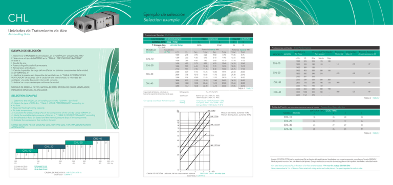
Ejemplo de selección Selection example CHL Unidades de Tratamiento de Aire Air Handling Units Prestaciones Baterías Coil Performance CAPACIDAD PERFORMANCE FRIO COOLING 5 BATERIA TIPO COIL TYPE Air inlet temp T. Entrada Aire MODELO MODEL EJEMPLO DE SELECCIÓN 1. Determinar el MODELO de climatizador, en el “GRÁFICO 1 CAUDAL DE AIRE” 2. Seleccionar el tipo de BATERÍAS en la “TABLA 1 PRESTACIONES BATERÍAS” en base a: • Caudal de aire. • Potencia frigorífica/calorífica necesaria. • Temperatura entrada aire. 3. Calcular la pérdida de carga del aire (Pa) de los distintos componentes de la unidad, en el “GRÁFICO 2”. 4.- Verificar la presión est. disponible del ventilador en la “TABLA 2 PRESTACIONES VENTILADOR” de acuerdo con el caudal de aire seleccionado, la velocidad del ventilador y la caída de presión interna del conjunto. 5.- Indicar los componentes que conforman la unidad. CHL-10 CHL-20 CHL-30 CHL-40 MÓDULO DE MEZCLA, FILTRO, BATERíA DE FRÍO, BATERÍA DE CALOR, VENTILADOR, PlENUM DE IMPULSIÓN, SILENCIADOR. CALOR HEATING 2 5 6 25/55 ������������������������������������������������������������� 27/62 15 15 °C / %HR Caudal Aire Air Flow m3/h. I/s. Sen. Potencia Capacity KW Total Sen. Total Potencia Capacity KW Total Total 1000 278 3.95 6.20 4.50 8.70 11.85 8.75 1200 333 4.35 6.90 5.10 9.70 12.55 10.05 1400 389 4.60 7.40 5.40 10.30 13.70 11.25 1450 403 5.75 8.95 6.70 12.60 16.70 12.65 1800 500 6.45 10.30 7.70 14.50 18.85 15.10 2150 597 7.05 11.35 8.30 15.80 20.25 17.25 2300 639 9.10 14.25 10.40 19.95 26.50 20.05 2800 778 10.10 16.05 11.70 22.55 29.30 23.45 3300 916 10.80 17.45 12.70 24.20 31.10 26.50 3000 833 11.90 18.55 13.60 26.05 34.55 26.20 3600 1000 13.00 20.60 15.10 29.00 37.65 4200 1167 13.30 22.20 16.10 30.80 41.05 30.20 33.70 TABLA 1 TABLE 1 Capacidad de Baterías, calculada en Refrigeración T.e. 7°C T.s.12°C base a las siguientes temperaturas de agua. Calefacción Batería tipo 2 T.e. 75°C T.s. 65°C Batería tipo 5 T.e. 45°C T.s. 40°C SELECTION EXAMPLE 1.-Determine the MODEL of air handling unit in the “GRAPH 1 (air flow)“. 2.- Select the type of COILS in “ Table 1, COILS PERFORMANCE “according to: • Air flow. • Required heating/cooling capacity. • Air inlet temperature. 3.- Calculate the pressure drop (Pa) of the components of the unit by using “GRAPH 2”. 4.- Verify the available static pressure of the fan in ” TABLE 2 FAN PERFORMANCE” according to the selected air flow, fan speed and the internal pressure drop of the components. 5.- Indicate the components that conform the unit. Coil capacity according to the following water Cooling Heating Prestaciones ventilador MODELO MODEL Fan Performance Caudal aire Air Flow Velocidad Ventilador Potencia Intensidad Fan speed Motor W m3/h. I/S. Alta Media Baja 1000 278 210 170 100 1200 333 180 110 - 1400 389 120 - - 1450 403 350 280 160 CHL-10 CHL-20 1800 500 340 210 2150 597 310 - 2300 639 250 220 200 CHL-30 2800 778 230 190 170 3300 916 190 160 - 3000 833 320 280 190 CHL-40 3600 1000 300 230 - 4200 1167 270 - - Max. A Presión Sonora Acustic pressure dB 147 2,3 47 420 4,4 47 500 5,5 48 500 5,5 49 TABLA 2 TABLE 2 Temperatures. Inlet T.7°C Outlet T.12°C Coil type 2 . Inlet T. 75°C Outlet T. 65°C Coil type 5 Inlet T. 45°C Outlet T. 40 ºC Caída de Presión Lado agua, de los componentes internos de la unidad Pressure Drop Water side, Kpa Módulo de mezcla, aumentar 15 Pa Plenum de impulsión, aumentar 20 Pa MIXING SECTION, FILTER, COOLING COIL, HEATING COIL, FAN, IMPULSION PLENUM, ATTENUATOR. MODEL MODELO BATERíA TIPO COIL TYPE 5 6 2 5 CHL-10 18 26 20 28 CHL-20 24 29 17 26 CHL-30 23 27 27 28 CHL-40 28 26 24 29 TABLA 3 TABLE 3 CHL-40 CHL-30 CHL-20 CHL-10 1 2 1000 278 (1) V. paso aire 1,8 m/s (2) V. paso aire 2,2 m/s (3) V. paso aire 2,6 m/s 1 2 1 1 2 2 3 3 3 3 1500 417 2000 555 2500 694 3000 835 4000 875 Presión ESTÁTICA TOTAL de los ventiladores (Pa), en función del caudal de aire. Ventiladores con motor incorporado, monofásicos. Tensión 220/240 V�. Nivel de presión sonora a 3mt. de distancia del aparato. Ensayos realizados con sección de mezcla y plenum de impulsión. Ventilador a velocidad media 4500 m3/h. 1250 l/sg Fan total static pressure (Pa), in function of air flow and fan speed. 1 �������������������������������������� Ph motor fan. Voltage 220/240V 50Hz Noise pressure level at 3 m. of distance. Tests carried with mixing section and outlet plenum. Fan speed regulated at medium value. (1) Air speed 1,8 m/s. (2) Air speed 2,2 m/s. (3) Air speed 2,6 m/s. CAUDAL DE AIRE m3/h l/s AIR FLOW m3/h l/s GRÁFICO 1 GRAPH 1 CAIDA DE PRESIÓN Lado aire, de los componentes internos PRESSURE DROP Air ���������� side, Kpa ��� GRÁFICO 2 GRAPH 2 DIMENSIONES DIMENSIONS Gaudí, 26 08120 La Llagosta (Barcelona) Tel. 93 544 38 30 Fax 93 544 38 31 Dimensiones Dimensions Modelos Models A B C D E F G H I K ØL ØM ØN COMPUERTAS Peso DAMPERS Weight CHL-10 370 750 700 240 250 400 300 340 710 250 150 3/4” 3/4” 300 x 200 58 CHL-20 430 950 800 275 310 400 300 380 910 320 200 3/4” 1 “ 400 x 300 89 CHL-30 480 1.200 800 305 345 500 300 440 1.160 427 250 1 “ 1/4” 400 x 400 111 CHL-40 580 1.200 900 350 405 500 300 540 1.160 397 250 1 “ 1/4” 500 x 400 143 www.servoclima.com [email protected] Dimensiones orientativas SERVO/CLIMA se reserva el derecho de modificar sin previo aviso las características y medidas de estos modelos CHL Climatizador Horizontal Unidades para el Tratamiento de Aire Air Handling Units Dimensiones orientativas. SERVO / CLIMA se reserva el derecho de modificar sin previo aviso las características y medidas de estos modelos. Indicative dimensions: SERVO/CLlMA reserves the right to modify without previous warning the characteristics and measures of these models. • Envolvente de chapa galvanizada y lacada, 1,2 mm de espesor. • Aislamiento térmico y acústico de gran capacidad de absorción a base de caucho (LA) de alta densidad y espuma de poliuretano tipo Ipacel. (Ver informe de ensayos) • Ventilador con motor incorporado de TRES VELOCIDADES equilibrados estática y dinámicamente. • Baterías construidas con tubos de cobre 3/8” y aletas de aluminio • Filtros con marco metálico y manta filtrante de fibra de vidrio, eficacia EU-3 • Registros de fácil acceso para inspección y mantenimiento, situados en los laterales de la unidad. La forma constructiva, permite el acceso al ventilador por la parte inferior de la unidad • Módulo de mezcla y plenum de impulsión opcional. • Bajo demanda se pueden construir de forma VERTICAL TECHNICAL CARACTERISTICS • Housing made of galvanized / prelaquered plate. Thickness 1,2mm. • High effectiveness thermal and acoustic insulation made of polyester foam. • THREE SPEED direct drived fan. Balanced static and dinamically. • Coils are 3/8“copper tube/aluminium plate fin construction . • Filters constructed with metallic frame and fiber glass. Efficiency EU-3 • Easy acces for inspection and maintenance in one side of the unit. The fan is accessible from the bottom of the unit. • Mixing module and outlet plenum on request. • VERTICAL construction is possible on request. CHL 05 Julio 2007 CARACTERÍSTICAS TÉCNICAS E O5
