notas modo de apresentaç®o
Anuncio
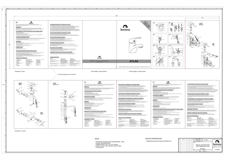
20 19 17 18 15 16 14 13 10 11 12 9 5 6 7 8 2 3 4 1 N G EN M 5 Thank you for choosing Sanitana products. It is our objective that this fitting always provides full satisfaction. Sanitana fittings are subject to meticulous quality controls during the entire manufacturing process, providing customers with a quality product that meets their day-to-day requirements. WARRANTY Sanitana guarantees the correct operation of this fitting for 5 YEARS, from the purchase date, against any manufacturing defects, visible or not, as long as the assembly, use and service, are in accordance with the handling and use instructions. Any defective fitting must be sent, postage paid, to Sanitana for examination, together with the purchase proof to validate the process. The warranty does not cover labour charges, call-out fees or indemnification. THE WARRANTY IS NOT APPLICABLE IN THE FOLLOWING CASES - Incorrect installation and/or servicing; - Accidents or incorrect handling; - Damage caused by low water quality (sand, limescale, etc.); - Normal wear of parts and consumables (seals, valves); - The use of abrasive or corrosive products on the fitting surface (solvents, strippers and acids, including whitening toothpastes); - Damage to the surface coating caused by removal of an installed fitting. L CLEANING RECOMMENDATIONS R YE A A N A R S WASHBASIN AND BIDET FITTINGS INSTALLATION FIG. 3 - Mount the threaded pins (13) and flexibles water supply tubs (15) on the fitting body (7), tightening them with a number 19 open end wrench. Mount the o-ring (10) on fittings body, resting it in the fastening fixture (bathroom vanity or washbasin). FIG. 4 - Mount the seal (11) and clamping collar (12) on the threaded pin (13), securing the entire assembly with the fastening nuts (14). FIG. 5 - To assemble the drain, insert the upper section of the valve (23) and respective seal (22) into the washbasin or vanity fixture. Position the lower part of the valve (20) underneath the washbasin or vanity fixture, ensuring that the lower seal (21) is correctly centred. Tighten the valve by screwing together the entire assembly to fix the body in position. FIG. 6 - Insert the rod (16) into the respective fixture on the fitting body, connecting it, further, with it's extension (17). Then, insert the white "sphere" - which will act as a ball joint - of the horizontal rod (19) into the valve body (20). Connect also the vertical extension to the horizontal part trought the supplied screw you'll find mounted together with the small metal plate (18), as illustrated in the figure. After mounting the rod and valve, perform the operational adjustment by the existing screw (18). The two supply tubes (15) may now be connected to the respective water intakes and the water supply may be turned on so that the fitting can be tested. Fig. 1 TI 5 W A Fig. 2 FRIA A N QUENTE CALIENTE HOT O S R R Lavabo Washbasin COLD A N TY BATHTUB AND SHOWER FITTINGS INSTALLATION Step 1: Attach the "S" connections (33) horizontally to the supply piping at a 150mm distance (Fig. 7); Step 2: Insert / screw on the two face cover fixtures (32) on the "S" connections; Step 3: Connect the fitting body (7) to the "S" connections ensuring that sealing washer (31) is inserted into place on both connections; Step 4: Connect the flexible showerhead supply tube (27) to the fitting body (7), mounting, if necessary, the showerhead holder on the wall. Fig. 3 Fig. 4 Fig. 5 Fig. 6 Fig. 7 Fig. 8 HOW TO USE THE BATHTUB SHUNT - Clean only with specific products for chrome-plated surfaces (without acids and solvents) using a soft cloth. The fitting may also be cleaned using lightly soaped water and damp cloth, then rinsing the fitting thoroughly with clean water and drying it with a soft cloth or towel; - To prevent limescale stains, clean the tap after each use; - The maintenance of the perlator (aerator) must be performed with a liquid limescale-removing product (Fig. 8). PRESSURE - Maximum working pressure: 16 bar; - Recommended working pressure: 5 bar; If working pressure is above the recommended value, a pressure reducer should be installed; - Minimum working pressure: 0.5 bar (0.8 bar for bathtub mixer); - Caudal at 3 bar: 8 litres/minute; - Caudal of washbasin, bidet and kicthen sink mixers at 3 bar: 12 litres/minute; - Caudal of bathtub and shower mixers at 3 bar: 20 litres/minute. J A TEMPERATURE - Turn on the tap and pull the shunt knob (25) upwards: the flow of water is diverted to the showerhead; - Turn off the tap: the shunt knob should return to its original position; - If everything functions as described in the abovementioned steps, the shunt is operating correctly; - Bear in mind that the minimum working pressure of the shunt is 0.8 bar; - If the shunt is not working correctly, unscrew and remove the shunt body (25), checking the condition of the seals; - Carefully clean the seals and, if necessary, coat them with a thin layer or lubricant. Remount the shunt. KITCHEN FITTING INSTALLATION Step 1: Insert the fitting with the o-ring (10) correctly mounted into the orifice where it is to be installed and pass the flexible connecting tubes (15) through the same orifice; Step 2: Mount the seal (11) and clamping collar (12) on the threaded pin (13), securing the entire assembly, with the supplied nuts (14), in the final fitting position; Step 3: Connect the two supply tubes (15) to the respective water intakes and turn the water supply on so that the fitting can be tested. Bidet REPLACING THE CARTRIDGE - Remove the fitting's lever (1) and the temperature symbol (3) and loosen the fastening screw (2) located under this symbol; - Unscrew the face cover fixture (4) and ring nut (5) and extract the cartridge (6); - To mount the cartridge, follow this procedure in the reverse order, ensuring that the internal surfaces of the fitting body are cleaned well and that the ring nut (5) is correctly tightened. PLEASE READ BEFORE STARTING INSTALLATION - The water supply must be turned off and the water contained in the pipes must also be expelled (Fig. 1); - Connecting supply tubes: hot water must be connected to the left-hand side of the fitting and cold water to the right-hand side (Fig. 1); - Do not twist or bend the supply tubes during assembly (Fig. 2); - Before testing the fitting, it is essential that the perlator/aerator is removed from the fitting and water is allowed to exit the fitting so that any impurities that could cause its blockage are expelled; - It is recommended installing filters between water supply piping and sanitary fittings; - If there is a large difference in pressure between the hot and cold water systems, the harmonisation of these pressures is advisable; - Adjust the rod of the automatic valve (washbasin and bidet fitting), using the existing adjustment mechanism (18), so that it operates correctly (Fig. 6). CLEANING OR REPLACING THE PERLATOR / AERATOR - Unscrew the perlator / aerator body (9) and clean the filters and seals inside it, removing any impurities that may exist; - To assemble, follow this precedure in the reverse order, taking care to mount the filters and seals in the correct order. TROUBLESHOOTING I TECHNICAL INFORMATION 14 - Elongated fastening nut 15 - Connecting supply tubes 16 - Rod 17 - Rod (vertical) extension 18 - Metal clamping plate + fixing screw 19 - Rod (horizontal component) 20 - Drain valve (lower body) 21 - Lower drain seal 22 - Upper drain seal 23 - Drain valve (upper body) 24 - Drain cap 25 - Shunt body 26 - Sealing washer POSSIBLE CAUSES PROBLEM 27 - Flexible shower head supply tube 28 - Fastening nut 29 - Sealing washer 30 - Male threaded nut 31 - Sealing washer 32 - Face cover fixture 33 - "S" connection 34 - Fitting upper body 35 - Seals 36 - Fitting lower body 37 - Seal 38 - Fitting body base SOLUTIONS Notable decrease in flow - Insufficient pressure - Perlator / Areator obstructed - Perlator / Areator deteriorated - Check system upstream - Clean Perlator / Areator - Replace Perlator / Areator Water leak from under the handle or under the hood - Cartridge not well tightened - Base seal or o-rings deteriorated - Water hammering on system - Tighten ring nut - Check condition of seals (clean or replace them) - Replace cartridge - Check system Malfunction of shunt or leakage - Shunt seal deteriorated - Disassemble and lean the sealed parts or replace the shunt completely Water leak from "S" connections caps - Cap seals deteriorated - Close caps or replace seals 150 mm ATLAS 3781-909 Anadia (Portugal) - T.:+351 231 519 500 - F.:+351 231 511 024 - e-mail: [email protected] www.sanitana.com 1h GT136085 1 - Lever body 2 - Lever fastening screw 3 - Temperature symbol 4 - Cartridge cover 5 - Ring nut 6 - Cartridge 7 - Fitting body 8 - Coupling ball-and-socket joint 9 - Perlator / Aerator 10 - O-ring 11 - Seal 12 - Clamping collar 13 - Threaded pin Instrucciones de montaje y utilization Assembly instructions and usage H G PT Banheira E Cozinha Cocina Kitchen Faucet Bathtub a ofrecerle un producto de calidad que responda a sus necesidades diarias. GARANTIA conjunto con los tornillos de ajuste (14); conjunto com os parafusos de aperto (14); A Sanitana garante o bom funcionamento desta torneira durante 5 ANOS, a partir da sua data de compra, contra qualquer defeito de fabrico, F - Accidentes o manejo incorrecto; - Acidentes ou manuseamento incorrecto; CONSEJOS DE LIMPIEZA CONSELHOS DE LIMPEZA de ducha en la pared. FUNCIONAMENTO DO INVERSOR NA TORNEIRA DE BANHEIRA secar a torneira com um pano ou flanela macios; - Se, ao efectuar estes passos, tudo se processar como descrito, o inversor funciona correctamente; - Si al afectuar estos pasos, todo el proceso se desarrolla tal y como se describe, el inversor funciona correctamente; - Na eventualidade de mau funcionamento, desenroscar e retirar o corpo do inversor (25), verificando, de seguida, o estado das juntas. Voltar retirar el cuerpo del inversor (25), comprobando inmediatamente el estado de las juntas existentes. Volver a colocar el inversor E TEMPERATURA - Caudal misturadoras Banheira e Duche a 3 bar: 20 litros/minuto. (14) existentes para ello, todo el conjunto en el lugar donde debe instalarse el grifo; 3er. Paso: Conectar los tubos flexibles (15) a las respectivas salidas de agua y abrir el suministro de agua para poder probar el grifo. para testar a torneira. TEMPERATURA CAMBIO DEL CARTUCHO D da torneira e apertar bem a porca anular (5). Duche Ducha Shower LIMPIEZA O CAMBIO DEL PERLATOR / AIREADOR - Desenroscar el cuerpo del perlator/aireador (9). Limpiar los filtros y divisor existentes en su interior para eliminar enventuales - Desenroscar o corpo do perlator/arejador (9); Limpar os filtros e vedantes existentes no seu interior para eliminar eventuais impurezas; - Para montagem, repetir este processo pela ordem inversa, tendo o cuidado em montar os filtros e vedantes na forma correcta. eventuais impurezas que possam entupir o sistema; 1 - Cuerpo del manecilla PROBLEMA 14 - Porca alongada de aperto - Perlator/arejador em mau estado 16 - Vareta 4 - Tapa - vistas do cartucho 5 - Porca anular 6 - Cartucho 7 - Corpo da torneira C 9 - Perlator/arejador 10 - O-ring 11 - Junta 30 - Porca interior 19 - Vareta (parte horizontal) 32 - Espelho tapa-vistas 25 - Corpo do inversor 34 - Corpo superior da torneira 35 - Juntas 36 - Corpo inferior da torneira 37 - Junta 38 - Base do corpo da torneira - Cartucho mal apertado Mau funcionamento do - Limpar o perlator/arejador - Substituir o perlator/arejador - Apertar a porca anular - Verificar o estado das juntas, limpando ou substituindo-as por novas - Substituir o cartucho - Verificar o sistema - Junta do inversor deteriorada - Desmontar e limpar as partes seladas ou substituir, por completo, o inversor - Juntas da porca deterioradas - Apertar a porca ou substituir as juntas 14 - Tuerca alargada de ajuste 15 - Tubos flexibles 4 - Tapa vista del cartucho 5 - Tuerca anular 6 - Cartucho 7 - Cuerpo del grifo POSIBLES CAUSAS importante de caudal - Perlator/aireador osbtruido - Perlator/aireador en mal estado - Revisar las instalaciones - Limpiar perlator/aireador - Cambiar perlator/aireador SOLUCIONES Perdida de agua por debajo de la caperuza - Juntas en mal estado - Revisar el estado de las juntas (limpielas 30 - Tuerca interior 32 - Embellecedor 10 - Anillo 11 - Junta 13 - Guia de rosca PROBLEMA 27 - Tubo flexible de ducha 25 - Cuerpo del inversor 34 - Cuerpo superior del grifo 35 - Juntas 36 - Cuerpo inferior del grifo 37 - Junta 38 - Base del cuerpo del grifo - Apretar la tuerca anular - Cambiar el cartucho por uno nuevo - Revisar el sistema Mal funcionamiento del inversor o perdida de agua - Junta del inversor deteriorada - Desmontar y limpiar las partes selladas o reemplazar el inversor Perdida de agua por la - Juntas de la tuerca deterioradas - Apretar la tuerca o reemplazar las juntas B NOTAS * TIPO LETRA: HELVETIC LIGHT (MECANORMA) - ARIAL A * TAMANHO PAPEL: 891 x 210 mm. (DIN A5) * CORES: NEGRO, GRIS OSCURO E GRIS CLARO. * COTAS EM mm. PARA TORNEIRAS ATLAS (Sanitana)

