Overbridge Shelf Assembly Etagère à arceau Conjunto
Anuncio
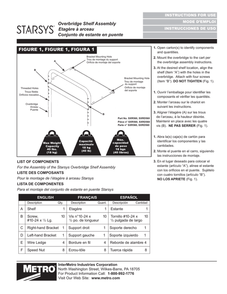
INSTRUCTIONS FOR USE MODE D’EMPLOI Overbridge Shelf Assembly Etagère à arceau Conjunto de estante en puente INSTRUCCIONES DE USO 1. Open carton(s) to identify components and quantities. FIGURE 1, FIGURE 1, FIGURA 1 Bracket Mounting Hole Trou de montage du support Orificio de montaje del soporte A 2. Mount the overbridge to the cart per the overbridge assembly instructions. B Bracket Mounting Hole Trou de montage du support Orificio de montaje del soporte Threaded Holes Trous filetés Orificios roscados 3. At the desired shelf location, align the shelf (Item “A”) with the holes in the overbridge. Attach with four screws (Item “B”). DO NOT TIGHTEN (Fig. 1). 1. 2. Monter l’arceau sur le chariot en suivant les instructions. Overbridge Arceau Puente B Part No. SXR560, SXRD560 Pièce n° SXR560, SXRD560 Parte n° SXR560, SXRD560 Max Weight Capacity 40 lbs. (18 kg) 1. Abra la(s) caja(s) de cartón para cantidades. Máx. capacidad de peso 18 kgs (40 libras) Capacité maximale 18 kg (40 lb) 2. Monte el puente en el carro, siguiendo las instrucciones de montaje. 3. En el lugar deseado para colocar el estante (artículo “A”), alinee el estante con cuatro tornillos (artículo “B”). NO LOS APRIETE (Fig. 1). LIST OF COMPONENTS For the Assembly of the Starsys Overbridge Shelf Assembly LISTE DES COMPOSANTS Pour le montage de l’étagère à arceau Starsys LISTA DE COMPONENTES Para el montaje del conjunto de estante en puente Starsys ENGLISH Description A Shelf B Screw, #10-24 x 1/2 Lg. FRANÇAIS Qty. 1 10 Description ESPAÑOL Quant. Etagère 1 Vis n°10-24 x /2 po. de longueur 10 1 3. Aligner l’étagère (A) sur les trous de l’arceau, à la hauteur désirée. Maintenir en place avec les quatre vis (B). NE PAS SERRER (Fig. 1). Descripción Cantidad Estante 1 Tornillo #10-24 x 10 /2 pulgada de largo 1 C Right-hand Bracket 1 Support droit 1 Soporte derecho 1 D Left-hand Bracket 1 Support gauche 1 Soporte izquierdo 1 E Wire Ledge 4 Bordure en fil 4 Reborde de alambre 4 F Speed Nut 8 Ecrou-tôle 8 Tuerca rápida InterMetro Industries Corporation North Washington Street, Wilkes-Barre, PA 18705 For Product Information Call: 1-800-992-1776 Visit Our Web Site: www.metro.com 8 Overbridge Shelf Assembly Etagère à arceau Conjunto de estante en puente FIGURE 2, FIGURE 2, FIGURA 2 D B B A C B FIGURE 3, FIGURE 3, FIGURA 3 B D B B E A B B C F F * Save this document for future application, load rating and/or safety reference. charge et/ou la référence de sécurité. * Conserve este documento en caso de que lo necesite en aplicaciones futuras, ! 4. Align front holes in brackets (Items “C” & “D”) with shelf. Secure with screws (Item “B”). DO NOT TIGHTEN (Fig. 2). 5. On one side, remove the two screws (Item “B”) holding the shelf in place, swing bracket in against the overbridge, aligning the holes in the bracket & shelf with the overbridge holes. Re-install the screws. Repeat for the opposite bracket. 6. Install four other screws (Item “B”) through shelf into brackets. TIGHTEN ALL SCREWS (Fig. 3). 7. If wire ledges are needed, drop the ledge(s) (Item “E”) into the holes in the shelf (Item “A”). Secure from the shelf underside by threading the speed nuts (Item “F”) onto the ends of the ledge(s)(Fig.3). 8. To remove wire ledges, simply unthread the nuts and lift off. 4. Aligner les trous avant des supports (C et D) sur l’étagère. Maintenir en place avec les vis (B). NE PAS SERRER (Fig. 2). 5. Enlever les deux vis (B) d’un côté, tout en maintenant l’étagère en place, faire pivoter le support contre l’arceau, aligner les trous du support et de l’étagère sur les trous de l’arceau. Remettre les vis en place. Répéter avec le support opposé. 6. Installer quatre autres vis (B) pour maintenir l’étagère sur le support. SERRER TOUTES LES VIS (Fig. 3). 7." $ (E) dans les trous de l’étagère (A). Du dessous de l’étagère, visser les écrous-tôle (F) sur les extrémi tés des bordures (Fig. 3). 8.% $" les écrous et de soulever les bordures. 4. ' (artículos “C” y “D”) con el estante. Sujételos con tornillos (artículo “B”). NO LOS APRIETE (Fig. 2). 5. En un lado, saque los dos tornillos (artículo “B”) que sujetan el estante en su lugar, haga oscilar el soporte hacia dentro contra el puente, alineando puente.Instale de nuevo los tornillos. Repita el procedimiento con el soporte opuesto. 6. Instale otros cuatro tornillos (artículo “B”) a través del estante, introduciéndolos en los soportes. APRIETE TODOS LOS TORNILLOS (Fig. 3). 7. Si fueran necesarios los rebordes de alambre, +69;<= doeel estante (artículo “A”). Sujételos desde la parte de debajo del estante, enroscando las tuer cas rápidas (artículo “F”) sobre los extremos de los estantes (Fig. 3). 8. Para retirar los rebordes de alambre, simplemente desenrosque las tuercas y levántelos. InterMetro Industries Corporation North Washington Street, Wilkes-Barre, PA 18705 For Product Information Call: 1-800-992-1776 Visit Our Web Site: www.metro.com L01-301 Rev A 01/2014
