89447 Instructions
Anuncio
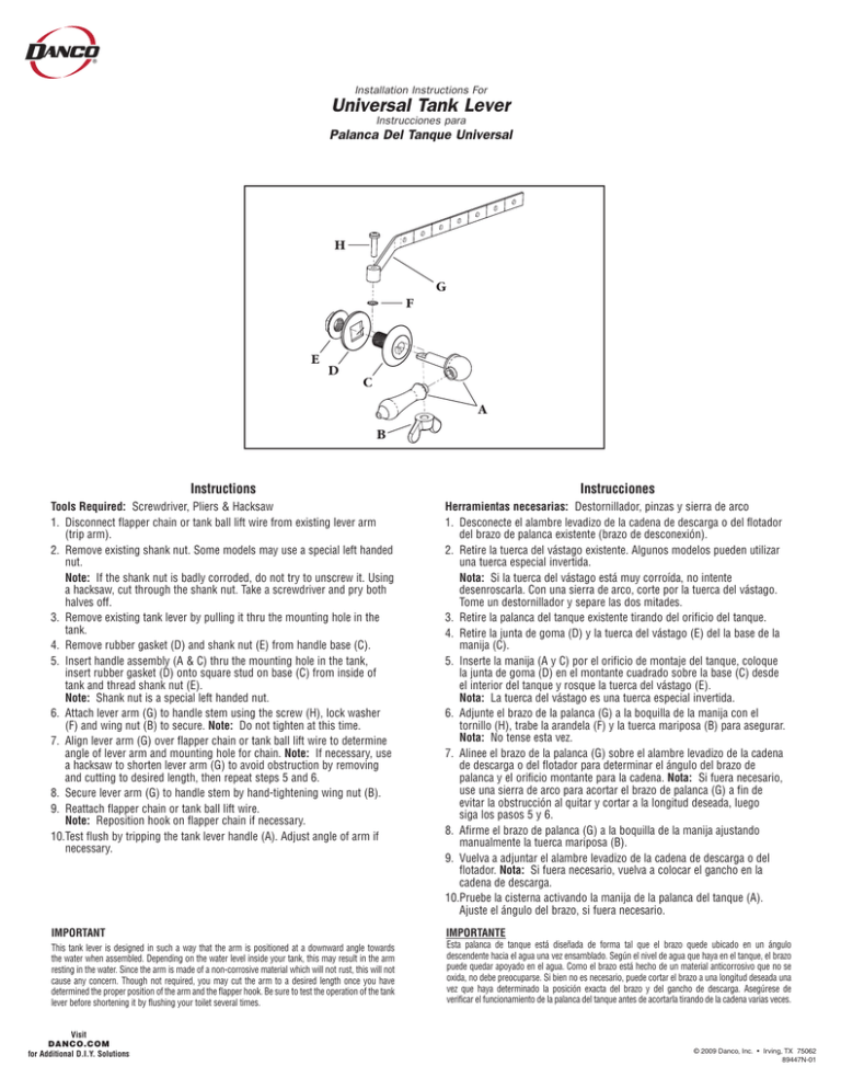
Installation Instructions For Universal Tank Lever Instrucciones para Palanca Del Tanque Universal H G F E D C A B Instructions Instrucciones Tools Required: Screwdriver, Pliers & Hacksaw 1. Disconnect flapper chain or tank ball lift wire from existing lever arm (trip arm). 2. Remove existing shank nut. Some models may use a special left handed nut. Note: If the shank nut is badly corroded, do not try to unscrew it. Using a hacksaw, cut through the shank nut. Take a screwdriver and pry both halves off. 3. Remove existing tank lever by pulling it thru the mounting hole in the tank. 4. Remove rubber gasket (D) and shank nut (E) from handle base (C). 5. Insert handle assembly (A & C) thru the mounting hole in the tank, insert rubber gasket (D) onto square stud on base (C) from inside of tank and thread shank nut (E). Note: Shank nut is a special left handed nut. 6. Attach lever arm (G) to handle stem using the screw (H), lock washer (F) and wing nut (B) to secure. Note: Do not tighten at this time. 7. Align lever arm (G) over flapper chain or tank ball lift wire to determine angle of lever arm and mounting hole for chain. Note: If necessary, use a hacksaw to shorten lever arm (G) to avoid obstruction by removing and cutting to desired length, then repeat steps 5 and 6. 8. Secure lever arm (G) to handle stem by hand-tightening wing nut (B). 9. Reattach flapper chain or tank ball lift wire. Note: Reposition hook on flapper chain if necessary. 10.Test flush by tripping the tank lever handle (A). Adjust angle of arm if necessary. Herramientas necesarias: Destornillador, pinzas y sierra de arco 1. Desconecte el alambre levadizo de la cadena de descarga o del flotador del brazo de palanca existente (brazo de desconexión). 2. Retire la tuerca del vástago existente. Algunos modelos pueden utilizar una tuerca especial invertida. Nota: Si la tuerca del vástago está muy corroída, no intente desenroscarla. Con una sierra de arco, corte por la tuerca del vástago. Tome un destornillador y separe las dos mitades. 3. Retire la palanca del tanque existente tirando del orificio del tanque. 4. Retire la junta de goma (D) y la tuerca del vástago (E) del la base de la manija (C). 5. Inserte la manija (A y C) por el orificio de montaje del tanque, coloque la junta de goma (D) en el montante cuadrado sobre la base (C) desde el interior del tanque y rosque la tuerca del vástago (E). Nota: La tuerca del vástago es una tuerca especial invertida. 6. Adjunte el brazo de la palanca (G) a la boquilla de la manija con el tornillo (H), trabe la arandela (F) y la tuerca mariposa (B) para asegurar. Nota: No tense esta vez. 7. Alinee el brazo de la palanca (G) sobre el alambre levadizo de la cadena de descarga o del flotador para determinar el ángulo del brazo de palanca y el orificio montante para la cadena. Nota: Si fuera necesario, use una sierra de arco para acortar el brazo de palanca (G) a fin de evitar la obstrucción al quitar y cortar a la longitud deseada, luego siga los pasos 5 y 6. 8. Afirme el brazo de palanca (G) a la boquilla de la manija ajustando manualmente la tuerca mariposa (B). 9. Vuelva a adjuntar el alambre levadizo de la cadena de descarga o del flotador. Nota: Si fuera necesario, vuelva a colocar el gancho en la cadena de descarga. 10.Pruebe la cisterna activando la manija de la palanca del tanque (A). Ajuste el ángulo del brazo, si fuera necesario. IMPORTANT IMPORTANTE This tank lever is designed in such a way that the arm is positioned at a downward angle towards the water when assembled. Depending on the water level inside your tank, this may result in the arm resting in the water. Since the arm is made of a non-corrosive material which will not rust, this will not cause any concern. Though not required, you may cut the arm to a desired length once you have determined the proper position of the arm and the flapper hook. Be sure to test the operation of the tank lever before shortening it by flushing your toilet several times. Esta palanca de tanque está diseñada de forma tal que el brazo quede ubicado en un ángulo descendente hacia el agua una vez ensamblado. Según el nivel de agua que haya en el tanque, el brazo puede quedar apoyado en el agua. Como el brazo está hecho de un material anticorrosivo que no se oxida, no debe preocuparse. Si bien no es necesario, puede cortar el brazo a una longitud deseada una vez que haya determinado la posición exacta del brazo y del gancho de descarga. Asegúrese de verificar el funcionamiento de la palanca del tanque antes de acortarla tirando de la cadena varias veces. Visit DANCO.COM for Additional D.I.Y. Solutions © 2009 Danco, Inc. • Irving, TX 75062 89447N-01
