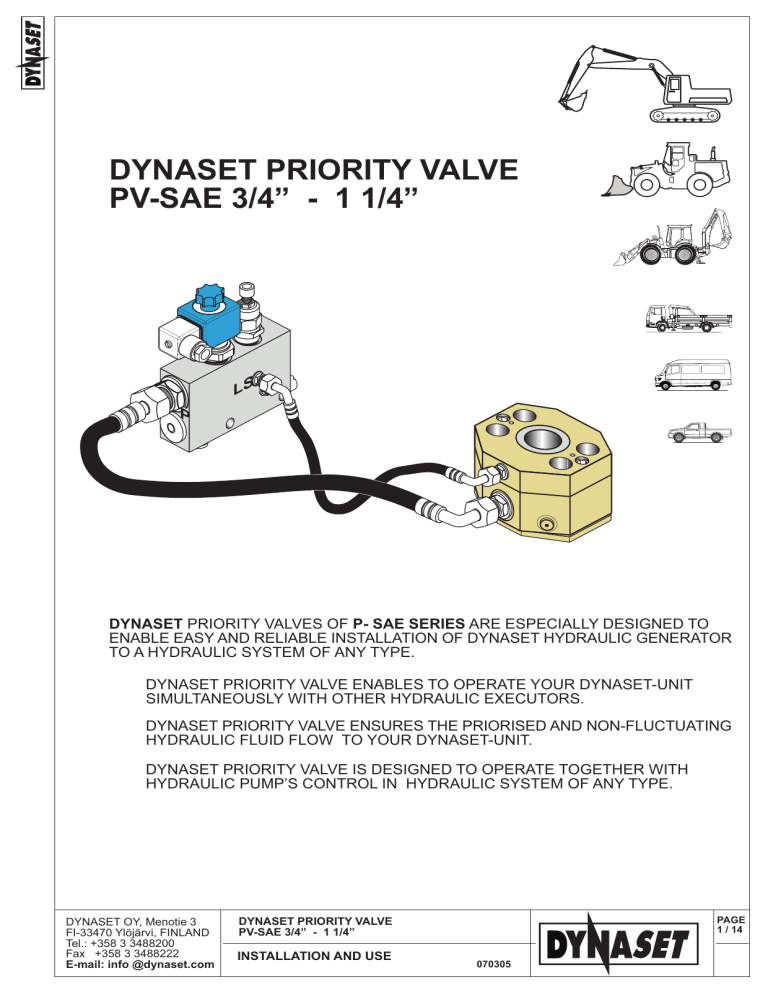
DYNASET PRIORITY VALVE PV-SAE 3/4 - 1 1/4 LS P DYNASET PRIORITY VALVES OF P- SAE SERIES ARE ESPECIALLY DESIGNED TO ENABLE EASY AND RELIABLE INSTALLATION OF DYNASET HYDRAULIC GENERATOR TO A HYDRAULIC SYSTEM OF ANY TYPE. DYNASET PRIORITY VALVE ENABLES TO OPERATE YOUR DYNASET-UNIT SIMULTANEOUSLY WITH OTHER HYDRAULIC EXECUTORS. DYNASET PRIORITY VALVE ENSURES THE PRIORISED AND NON-FLUCTUATING HYDRAULIC FLUID FLOW TO YOUR DYNASET-UNIT. DYNASET PRIORITY VALVE IS DESIGNED TO OPERATE TOGETHER WITH HYDRAULIC PUMPS CONTROL IN HYDRAULIC SYSTEM OF ANY TYPE. DYNASET OY, Menotie 3 FI-33470 Ylöjärvi, FINLAND Tel.: +358 3 3488200 Fax +358 3 3488222 E-mail: info @dynaset.com PAGE 1 / 14 DYNASET PRIORITY VALVE PV-SAE 3/4 - 1 1/4 INSTALLATION AND USE 070305 DYNASET PV-SAE priority valve includes following components: 1. Sandwich-mounted PRESSURE COMPENSATOR (PC-SAE) with SAE-flange specification; Pressure compensator includes one seal flange (1.20) as standard. 2. LS-VALVE 2.2 Solenoid valve 12/24V; 2.3 Flow limiting valve. 2.4 Pressure relief valve. 3. AN OPTIONAL height adjustment kit. 5-6. HYDRAULIC HOSES. CONSTRUCTION I VALVE MODEL PC-SAE size LSV model p max bar Q CF, max * l/min PV-SAE 3/4-40-xx lpm-12/24 V PV-SAE 3/4-60-xx lpm-12/24 V PV-SAE 1-40-xx lpm-12/24 V PV-SAE 1-60-xx lpm - 12/24 V PV-SAE 1 1/4-40-xx lpm -12/24 V PV-SAE 1 1/4 -60-xxx lpm -12/24 V 3/4 3/4 1 1 1 1/4 1 1/4 LSV 40 LSV 60 LSV 40 LSV 60 LSV 40 LSV 60 350 350 350 350 350 350 35 55 35 55 35 55 * CF-rate is adjusted at factory to the value specified by a customer 2.2 2.4 T LS 1 Q2 CF 2.3 P 2 6 1.20 5 PV-SAE valve B LS LS P P CF 3 CF - BSP 3/4 T - BSP 1/2 A Q1 T DYNASET OY, Menotie 3 FI-33470 Ylöjärvi, FINLAND Tel.: +358 3 3488200 Fax +358 3 3488222 E-mail: info @dynaset.com PAGE 2 / 14 DYNASET PRIORITY VALVE PV-SAE 3/4 - 1 1/4 INSTALLATION AND USE 070305 CONSTRUCTION II VALVE MODEL PC-SAE size LSV model P max bar Q CF, max * l/min PV-SAE 3/4-95-xxx lpm-12/24 V 3/4 LSV 95 350 85 PV-SAE 1-95-xxx lpm - 12/24 V 1 LSV 95 350 85 PV-SAE1 1/4 -95-xxx lpm-12/24 V 1 1/4 LSV 95 350 85 * CF-rate is adjusted at factory to the value specified by a customer 2.2 Q2 1 CF 2.4 6 T 2.3 5 1.20 CF - BSP 3/4 T - BSP 3/4 PV-SAE valve B LS LS P P CF 3 A T Q1 DYNASET OY, Menotie 3 FI-33470 Ylöjärvi, FINLAND Tel.: +358 3 3488200 Fax +358 3 3488222 E-mail: info @dynaset.com PAGE 3 / 14 DYNASET PRIORITY VALVE PV-SAE 3/4 - 1 1/4 INSTALLATION AND USE 070305 CONSTRUCTION III VALVE MODEL PC-SAE size LSV model P max bar Q CF, max * l/min PV-SAE 3/4-150-xxx lpm-12/24 V 3/4 LSV 150 350 140 PV-SAE 1-150-xxx lpm - 12/24 V 1 LSV 150 350 140 PV-SAE 1 1/4 -150-xxx lpm -12/24V 1 1/4 LSV 150 350 140 * CF-rate is adjusted at factory to the value specified by a customer 2.2 Q2 CF 6 1 2.3 T 2.4 2.3 1.20 5 CF - BSP 3/4 T - BSP 3/4 PV-SAE valve B LS LS P P 3 CF Q1 A T DYNASET OY, Menotie 3 FI-33470 Ylöjärvi, FINLAND Tel.: +358 3 3488200 Fax +358 3 3488222 E-mail: info @dynaset.com PAGE 4 / 14 DYNASET PRIORITY VALVE PV-SAE 3/4 - 1 1/4 INSTALLATION AND USE 070305 INSTALLATION 1. OPEN CENTRE HYDRAULIC SYSTEM WITH VARIABLE DISPLACEMENT PUMP AUTOMATIC ROTATION SPEED CONTROL VALVE T P S M PV-SAE priority valve is designed for the installation to a main pressure line (ref. to pages 5 - 7). Pre-adjusted, independent from other functions and priorised hydraulic flow for DYNASET-unit comes from the solenoid valve. PV-SAE valve G B LS LS P P HG HMG HWG CF A T 6 T 1 LS 5 CF P HG 2 CF 6 LS 1 T 5 2 DYNASET OY, Menotie 3 FI-33470 Ylöjärvi, FINLAND Tel.: +358 3 3488200 Fax +358 3 3488222 E-mail: info @dynaset.com P PAGE 5 / 14 DYNASET PRIORITY VALVE PV-SAE 3/4 - 1 1/4 INSTALLATION AND USE HG 070305 INSTALLATION 2. HYDRAULIC SYSTEM WITH CONSTANT DISPLACEMENT PUMP AUTOMATIC ROTATION SPEED CONTROL VALVE T P S M PV-SAE valve B LS LS P P G CF HG HMG HWG A T 6 T 1 LS 5 CF P HG 2 CF 6 LS 1 T 5 2 DYNASET OY, Menotie 3 FI-33470 Ylöjärvi, FINLAND Tel.: +358 3 3488200 Fax +358 3 3488222 E-mail: info @dynaset.com HG P PAGE 6 / 14 DYNASET PRIORITY VALVE PV-SAE 3/4 - 1 1/4 INSTALLATION AND USE 070305 INSTALLATION OPTIONS FOR AN INSTALLATION OF PRESSURE COMPENSATOR TO THE OPEN CENTRE HYDRAULIC SYSTEMS 1 L P 1 L DYNASET OY, Menotie 3 FI-33470 Ylöjärvi, FINLAND Tel.: +358 3 3488200 Fax +358 3 3488222 E-mail: info @dynaset.com PAGE 7 / 14 DYNASET PRIORITY VALVE PV-SAE 3/4 - 1 1/4 INSTALLATION AND USE 070305 INSTALLATION 3. CLOSED CENTRE HYDRAULIC SYSTEM WITH VARIABLE DISPLACEMENT PUMP AUTOMATIC ROTATION SPEED CONTROL VALVE T P S M G LS HG HMG HWG CF P T LS valve It is recommended to install DYNASET hydraulic generator to a closed centre hydraulic system of an excavator (see diagram above) without pressure compensator, using only a LS-valve of required capacity. Installed to a closed centre hydraulic system of a modern excavator, pressure compensator may cause certain deceleration of machines movements and functions when the priorised flow to the generator is on - pls. consult DYNASETs experts ! For all other carriers with closed centre hydraulics (fire trucks etc.) an installation of DYNASET hydraulic generator can be made using a complete PV SAE valve . 6 T 1 LS 5 CF P 2 DYNASET OY, Menotie 3 FI-33470 Ylöjärvi, FINLAND Tel.: +358 3 3488200 Fax +358 3 3488222 E-mail: info @dynaset.com PAGE 8 / 14 DYNASET PRIORITY VALVE PV-SAE 3/4 - 1 1/4 INSTALLATION AND USE HG 070305 OPERATION When an excavators engine is on without any executor being used, a hydraulic pump levels to the idle mode, producing the flow conditioned by the hydraulic system of a machine. Q2 LS 12/24 VDC T LS P P CF Q1 DYNASET hydraulic generator is started by activating a solenoid valve of LS-valve, when hydraulic fluid flows in circuit Q1 - P - P - CF through pressure compensator and LS-valve. Flow limiting valve permits only the pre-adjusted throughflow when an excessive fluid goes to the main pressure line (Q1-Q2). Pressure compensator changes its throughput capacity being controlled by LS-signal. Hydraulic pump adjusts its output capacity in accordance with the mentioned LS-signal as well as with the LS-signal of the machines hydraulic system. Pressure relief valve of LS-valve protects the hydraulic generator against damaging by directing the hydraulic fluid to the tank (T) if pressure rises over the limit. When any other hydraulic operating unit (cylinder, motor, PTO etc.) is being actuated, PC-SAE, having ensured demanded and PRIORISED hydraulic flow to the DYNASET unit (CF), opens main supply line directing requested hydraulic flow for the corresponding function. Operation of a pressure compensator is controlled by a LS-signal according to a current capacity request. If controlled flow (CF) for DYNASET-unit is not requested, solenoid valve closes corresponding circuit and all the hydraulic flow is at systems disposal. Q2 LS CONTROL V O LTA G E T = 0 l/min LS Q1 P P CF = 0 l/min When the compressive force of hydraulic flow in main supply line exceeds the spring force of PC SAE, the incorporated valve of pressure compensator closes tightly excluding leakage flow. DYNASET OY, Menotie 3 FI-33470 Ylöjärvi, FINLAND Tel.: +358 3 3488200 Fax +358 3 3488222 E-mail: info @dynaset.com PAGE 9 / 14 DYNASET PRIORITY VALVE PV-SAE 3/4 - 1 1/4 INSTALLATION AND USE 070305 PRESSURE COMPENSATOR DYNASET PC-SAE Q2 L A W H LS B P MP S PC-SAE 1 PC-SAE 1 1/4 A B mm mm 23 49 27,2 55,6 31,5 63,5 L W H mm mm mm 68 67,5 63 73 82 65 89 95 72 BSP 3/4 BSP 1/8 BSP 1/4 BSP 3/4 BSP 1/8 BSP 1/4 BSP 3/4 BSP 1/8 BSP 1/4 3 6 3 6 3 6 P (CF) LS MP Q1 PC-SAE 3/4 SE AD mm mm OPTIONS: 1 HEIGHT ADJUSTMENT KIT SEALING PLATE (SE); ADAPTER PLATE (AD). 2 BOLTS (4-8 pcs), metric or imperial. S A PC-SAE 3/4 PC-SAE 1 PC-SAE 1 1/4 OPENING PRESSURE BAR 13,5 14 17,5 MAX. PRESSURE BAR 350 350 350 MAX. FLOW Q1 - Q2 L/MIN 200 350 450 MAX. FLOW Q1 - P L/MIN 70 100 145 BAR BAR 2,9 3,0 2,8 3,0 3,0 3,5 SAE 3/4 SAE 1 SAE 1 1/4 PRESSURE DROP AT MAX. FLOW Q1 - Q2 completely open Q1 - P SAE - FLANGE 3000 - 6000 psi PRESSURE HOSE LENGTH SIZE mm 800 R 1/2 800 R 5/8 800 R 3/4 CONTROL HOSE LENGTH SIZE mm 1000 R 1/4 1000 R 1/4 1000 R 1/4 DYNASET OY, Menotie 3 FI-33470 Ylöjärvi, FINLAND Tel.: +358 3 3488200 Fax +358 3 3488222 E-mail: info @dynaset.com PAGE 10/ 14 DYNASET PRIORITY VALVE PV-SAE 3/4 - 1 1/4 INSTALLATION AND USE 070305 PRESSURE COMPENSATOR DYNASET PC-SAE A Detach the pressure line flange from the hydraulic pump. 1 2 B Gauge dimensions A and B on the pumps flange. 4. A EACH DYNASET PRESSURE COMPENSATOR COVERS TWO SAE-SPECIFICATIONS WITHIN ONE FLANGE SIZE. 3 B Make an installation of chosen PC-SAE between the pump and pressure line SAE-flange. Choose an appropriate PC SAE pressure compensator to meet specifications of your machine. A, mm B, mm 22,2 23,8 47,6 50,8 SAE 3000 psi SAE 6000 psi 23 49 PC-SAE 3/4 A, mm B, mm 26,2 27,8 52,4 57,2 SAE 3000 psi SAE 6000 psi 27,2 55,6 PC-SAE 1 A, mm B, mm 30,2 31,7 58,7 66,7 SAE 3000 psi SAE 6000 psi 31,5 63,5 PC-SAE 1 1/4 DYNASET OY, Menotie 3 FI-33470 Ylöjärvi, FINLAND Tel.: +358 3 3488200 Fax +358 3 3488222 E-mail: info @dynaset.com NOTE ! When fitting a pressure compensator is ESSENTIAL that the bolts are tightened to the recommended torque value and in the correct sequence. Neglecting this may cause the risk of either the bolts working loose resulting in oil leakage (not tight enough), or damage to and possible shearing of the bolt (over tightened). The tightening is to be made in two steps according to the sequence sketched below. First tighten all bolts app. to 1/2 of rated torque and then carry out the tightening up to necessary. 1 4 Tightening torque values can be found from an engineering handbook according to the bolts size, 3 2 thread type and strength class. Find referential values on next page. PAGE 11/ 14 DYNASET PRIORITY VALVE PV-SAE 3/4 - 1 1/4 INSTALLATION AND USE 070305 STUD BOLTS FOR DYNASET PC-SAE L WHITWORTH THREAD METRIC THREAD TORQUE Nm SIZE L mm SIZE UNC/UNF TORQUE Nm LB/FT 45 M10 170 180 3/8 40 29,5 80 M12 170 7/16 75 55,5 110 M14 190 1/2 90 66,5 VALVE MODEL LSV PC SAE PV-SAE 3/4-40-xx lpm-12 V PV-SAE 3/4-40-xx lpm-24 V 9011514-12 9011514-24 LSV 40 LSV 40 07031366-12 07031366-24 3/4 3/4 9010393 9010393 PV-SAE 3/4-60-xx lpm-12 V PV-SAE 3/4-60-xx lpm-24 V 9011515-12 9011515-24 LSV 60 LSV 60 07031365-12 07031365-24 3/4 3/4 9010393 9010393 PV-SAE 1-40-xx lpm - 12 V PV-SAE 1-40-xx lpm - 24 V 9011516-12 9011516-24 LSV 40 LSV 40 07031366-12 07031366-24 1 1 9010406 9010406 PV-SAE 1-60-xx lpm - 12 V PV-SAE 1-60-xx lpm - 24 V 9011522-12 9011522-24 LSV 60 LSV 60 07031365-12 07031365-24 1 1 9010406 9010406 PV-SAE 1 1/4-40-xx lpm-12V PV-SAE 1 1/4-40-xx lpm-24V 9011523-12 9011523-24 LSV 40 LSV 40 07031366-12 07031366-24 1 1/4 9010409 1 1/4 9010409 PV-SAE 1 1/4-60-xx lpm-12V PV-SAE 1 1/4-60-xx lpm-24V 9011524-12 9011524-24 LSV 60 LSV 60 07031365-12 07031365-24 1 1/4 9010409 1 1/4 9010409 PV-SAE 3/4-95-xx lpm-12V PV-SAE 3/4-95-xx lpm-24V 9011526-12 9011526-24 LSV 95 LSV 95 07031364-12 07031364-24 3/4 3/4 9010393 9010393 PV-SAE 1-95-xx lpm - 12V PV-SAE 1-95-xx lpm - 24V 9011527-12 9011527-24 LSV 95 LSV 95 07031364-12 07031364-24 1 1 9010406 9010406 PV-SAE 1 1/4-95-xx lpm -12V 9011528-12 PV-SAE 1 1/4-95-xx lpm -24V 9011528-24 LSV 95 LSV 95 07031364-12 07031364-24 1 1/4 9010409 1 1/4 9010409 PV-SAE 3/4-150-xxx lpm-12V 9011529-12 PV-SAE 3/4-150-xxx lpm-24V 9011529-24 LSV 150 07031367-12 LSV 150 07031367-24 3/4 3/4 9010393 9010393 PV-SAE 1-150-xxx lpm-12V PV SAE 1-150-xxx lpm-24V 9011530-12 9011530-24 LSV 150 07031367-12 LSV 150 07031367-24 1 1 9010406 9010406 PV-SAE1 1/4-150-xxx lpm-12V 9011531-12 PV-SAE1 1/4-150-xxx lpm-24V 9011531-24 LSV 150 07031367-12 LSV 150 07031367-24 1 1/4 9010409 1 1/4 9010409 DYNASET OY, Menotie 3 FI-33470 Ylöjärvi, FINLAND Tel.: +358 3 3488200 Fax +358 3 3488222 E-mail: info @dynaset.com PAGE 12/14 DYNASET PRIORITY VALVE PV-SAE 3/4 - 1 1/4 INSTALLATION AND USE 070305 HOW TO ORDER: 1. 2. 3. PRESSURE COMPENSATOR is to be chosen according to the main pumps flange size. LS-VALVE is to be chosen according to the required oil flow (CF). NOTE ! Flow limiting valve is adjusted at factory to the requested value and can not be re-adjusted ! SOLENOID VALVEs COIL is to be chosen according to the on-board voltage of a vehicle (12 or 24 VDC). PV-SAE PRODUCT GROUP 1 40 xxx lpm 12 V PV-SAE PC-SAE SIZE 3/4 1 1 1/4 PRESSURE COMPENSATOR PC-SAE IS AVAILABLE SEPARATELY: PC-SAE INCORPORATED LS-VALVE NOMINAL SIZE, LPM 40 60 95 150 3/4 1 1 1/4 FACTORY ADJUSTMENT (LPM) CONTROL VOLTAGE (V DC) 12 V 24 V HYDRAULIC FLUIDS Wide range of standard hydraulic fluids can be used with the DYNASET hydraulic equipment. Depending on the operating temperature, following mineral hydraulic oils are recommended: ISO VG 32S for oils operation temperature up to 70 °C; ISO VG 46S for oils operation temperature up to 80 °C; ISO VG 68S for oils operation temperature up to 90 °C. Synthetic and bio-oils can be used as well if their viscosity characteristics and lubricating efficiency are corresponding to above mineral oils. Automatic transmission fluids and even engine oils can be used, provided that they are allowed to be used in hydraulic system of your carrier machine. To use special hydraulic fluids a with DYNASET equipment, please be kindly requested to contact nearest DYNASET representative for an advice. SAFETY PRECAUTIONS The pressure in hydraulic fluid circuit is considerably high. Thereat the technical condition of your equipment should be under constant scrutiny. Especially couplings, valves and hoses should be maintained tight and clean as well as kept under constant observation. Hydraulic leakages must be rectified immediately to avoid injuries caused by pressure and hot oil blowouts. Follow all your local safety instructions related to the high pressure hydraulics. Hydraulic system of a carrier machine should be maintained according to the service program. In order to exclude possible accidents, it is not allowed to clean or inspect PV SAE valve when hydraulic fluid circuit is pressurised. Prior to any cleaning, inspection and service hydraulic system of your carrier machine must be stopped and all hydraulic fluid circuits dissipated. Always wear appropriate clothing and safety equipment such as goggles, ear protection and safety shoes at all times when maintaining the PV SAE valve. Beware of machinery parts warmed by hot hydraulic oil. AN EXTERME CLEANLINESS MUST BE MAINTAINED WHEN CARRYING OUT ANY SERVICE DISSASSEMBLING OR REPAIR OF HRN-TOOL AND HYDRAULIC SYSTEM. THIS IS CRUCIAL TO ENSURE SAFE, RELIABLE AND LONG-LIFE OPERATION OF YOUR EQUIPMENT. Operators and maintenance personnel must always comply with local safety regulations and precautions in order to close out the possibility of damages and accidents. All installation and service of both hydraulic and electric equipment must be performed by qualified and experienced personnel only. DYNASET OY, Menotie 3 FI-33470 Ylöjärvi, FINLAND Tel.: +358 3 3488200 Fax +358 3 3488222 E-mail: info @dynaset.com PAGE 13/14 DYNASET PRIORITY VALVE PV-SAE 3/4 - 1 1/4 INSTALLATION AND USE 070305 MANUFACTURERS LIMITED WARRANTY 1. Warranty coverage All hydraulic accessories manufactured by DYNASET OY are subject to the terms and conditions of this limited warranty. Products are warranted to the original purchaser to be free from defects in materials or workmanship. Exclusions from warranty are explained in item 8. 2. Beginning of warranty period Warranty period begins from the delivery date of the product. Delivery is considered to be done on the date when installation has been accomplished or purchaser has taken the product in use. Product is considered as taken in use at the date when DYNASET OY has delivered the product to purchaser, unless separately agreed otherwise by written agreement. 3. 4. 5. Warranty period Warranty period is twelve (12) months based on maximum of 2000 hours usage during this time period. In cases where the system is provided complete with certain special components (e.g. drive unit), those components are considered as a subject to their manufacturers warranty. Warranty procedures Immediately upon identifying a problem which purchaser believes to be a failure subject to the products limited warranty, purchaser must contact primary to the seller of the product. Contact must be made as soon as possible, latest thirty (30) days after the problem was identified. Seller and/or manufacturer technical staff determines the nature of the problem primarily by phone or e-mail. Purchaser commits to give necessary information and to perform routine diagnostic procedures in order to determine the nature of the problem and necessary procedures. Warranty repairs If the product is found to be defective during the warranty period, DYNASET OY will, at its option, either repair the product, author it to be repaired at its authorized workshop or exchange the defective product. If the product must be repaired elsewhere than premises of DYNASET OY or authorized workshop, all costs excluded from this warranty (traveling and waiting hours, daily allowance, traveling expenses and uninstallation/reinstallation costs) will be charged from the purchaser. If the problem is not covered by this limited warranty, DYNASET OY has the right to charge purchaser of troubleshooting and repairing. DYNASET OY, Menotie 3 FI-33470 Ylöjärvi, FINLAND Tel.: +358 3 3488200 Fax +358 3 3488222 E-mail: info @dynaset.com 6. - Delivery terms of warranty repair If the product is found possible to be defective under this limited warranty and it needs to be repaired, DYNASET OY gives Warranty Return Number (WRN). Items being returned must be shipped, at the purchasers cost, adequately packed for shipment, to the DYNASET OY or to other location authored by DYNASET OY. Shipment documents must contain: Purchasers name and contact information Receipt of original purchase WRN code Problem description 7. Warranty of repaired product Warranty period of the product repaired under this limited warranty continues to the end of original warranty period. 8. Exclusions from warranty This warranty shall not apply to: a. Failures due to normal wear and tear, improper installation, misuse, abuse, negligence, purchaser selection of improper product to intended use, accident, improper filtration of hydraulic oil or intake water or lack of maintenance b. Cost of maintenance, adjustments, installation or startup c. Coating, hydraulic oil, quick couplings and interconnection hoses (internal or external to system assemblies) d. Products altered or modified in a manner not authorized by DYNASET OY in writing e. Products which have been repaired during warranty period by others than DYNASET OY or its authorized workshop f. Costs of any other damage or loss, whether direct, indirect, incidental, special or consequential, arising out of the use of, or the inability to use, the product g. Telephone or other communications expense h. Product that is used in exceptional conditions, considered to cause excessive wear and tear i. Faults caused by nature phenomenons like flood, thunder, etc. © DYNASET OY, all rights reserved PAGE 14/14 DYNASET PRIORITY VALVE PV-SAE 3/4 - 1 1/4 INSTALLATION AND USE 070305
