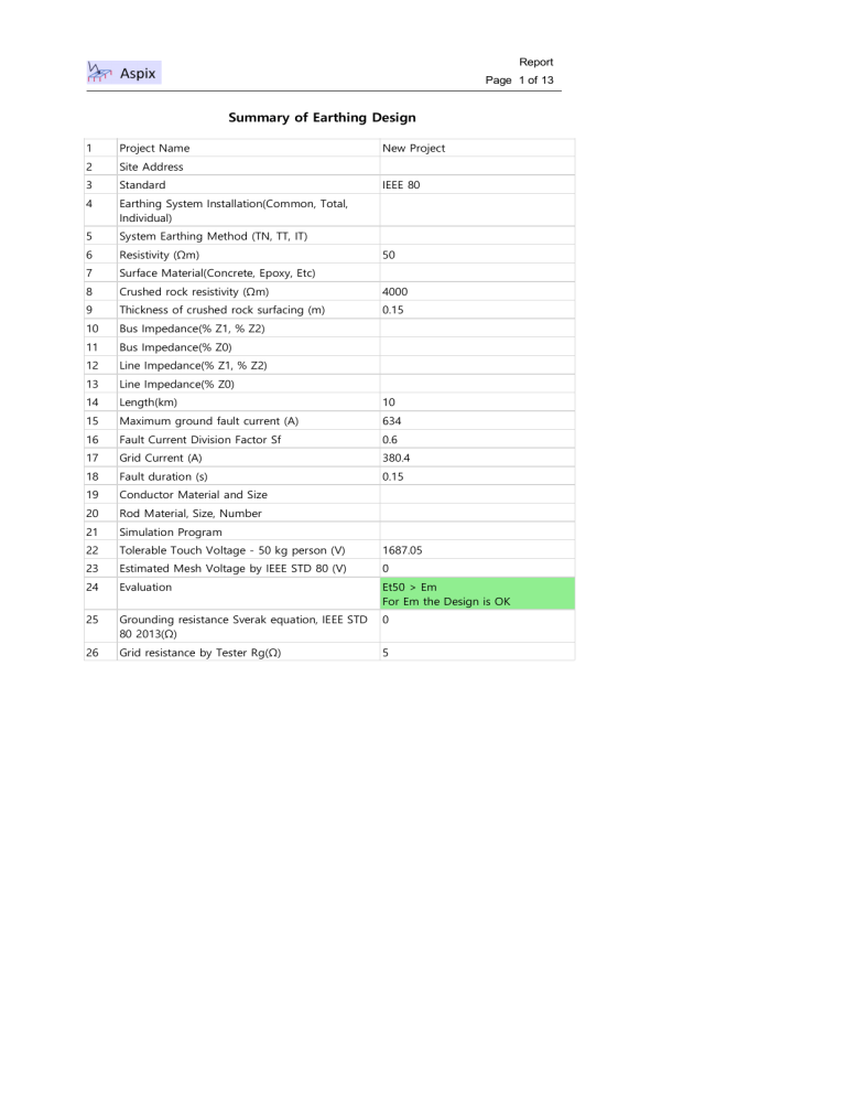
Report Page 1 of 13 Summary of Earthing Design 1 Project Name 2 Site Address New Project 3 Standard 4 Earthing System Installation(Common, Total, Individual) 5 System Earthing Method (TN, TT, IT) 6 Resistivity (Ωm) 7 Surface Material(Concrete, Epoxy, Etc) 8 Crushed rock resistivity (Ωm) 4000 9 Thickness of crushed rock surfacing (m) 0.15 10 Bus Impedance(% Z1, % Z2) 11 Bus Impedance(% Z0) 12 Line Impedance(% Z1, % Z2) 13 Line Impedance(% Z0) 14 Length(km) 10 15 Maximum ground fault current (A) 634 16 Fault Current Division Factor Sf 0.6 17 Grid Current (A) 380.4 18 Fault duration (s) 0.15 19 Conductor Material and Size 20 Rod Material, Size, Number 21 Simulation Program 22 Tolerable Touch Voltage - 50 kg person (V) 1687.05 23 Estimated Mesh Voltage by IEEE STD 80 (V) 0 24 Evaluation Et50 > Em For Em the Design is OK 25 Grounding resistance Sverak equation, IEEE STD 80 2013(Ω) 0 26 Grid resistance by Tester Rg(Ω) 5 IEEE 80 50 Report Page 2 of 13 Simplified Analysis Results No Symbol 1 - Earthing System Installation(Common, Total, Individual) 2 - System Earthing Method (TN, TT, IT) 3 - Conductor Material and Size 4 - Rod Material, Size, Number 5 If Maximum ground fault current (A) 6 IG Grid Current (A) 0 7 Sf Fault Current Division Factor Sf 0 8 Cp System Expanding factor 1.0 9 ρ Resistivity (Ωm) 50 10 ρs Crushed rock resistivity (Ωm) 4000 11 hs Thickness of crushed rock surfacing (m) 0.15 12 tf Fault duration (s) 0.15 13 h Depth of ground grid conductors (m) 0.6 14 n Geometric factor 15 d Diameter grid conductors (m) 16 D Spacing between parallel conductors (m) 5 17 LR Total length of ground rods(m) 0 18 Lx Maximum length of grid conductors in x direction (m) 0 19 Ly Maximum length of grid conductors in y direction (m) 0 20 Ta Ambient Temperature (°C) 32 21 Tm Fusing temperature Tm (°C) 0 22 Rg Grounding resistance Sverak equation, IEEE STD 80 2013(Ω) 0 23 EPR GPR Sverak resistance, IEEE STD 80 2013(V) 0 24 Em Estimated Mesh Voltage by IEEE STD 80 (V) 0 25 Es Estimated Step Voltage by IEEE STD 80 (V) 0 26 Et70 Tolerable Touch Voltage - 70 kg person (V) 2283.34 27 Et50 Tolerable Touch Voltage - 50 kg person (V) 1687.05 28 Properties Value 634 0 0.01 Evaluation Et50 > Em For Em the Design is OK 29 Es70 Tolerable Step Voltage - 70 kg person (V) 7917.23 30 Es50 Tolerable Step Voltage - 50 kg person (V) 5849.67 31 Evaluation Es50 > Es For Es the Design is OK Report Page 3 of 13 Grid Report Page 4 of 13 Grid 3D Report Page 5 of 13 Touch Voltage (V) Report Page 6 of 13 Step Voltage (V) Report Page 7 of 13 Touch Voltage 2D (V) Report Page 8 of 13 Step Voltage 2D (V) Resistivity (Ωm) Properties Value No Symbol 1 ROMAX Maximum resistivity (Ωm) 0 2 ROMIN Minimum resistivity (Ωm) 0 3 ROAVG Average of resistivity (Ωm) 0 4 ROSTDEV Standard deviation of resistivity (Ωm) 0 5 ROSTDEVP Standard deviation of resistivity (%) 0 6 RO70 Resistivity with 70% probability of not being exceeded (Ωm) 0 7 (ROMAX +ROMIN)/2 Average of resistivity between maximum and minimum values (Ωm) 0 8 RO1 Upper layer resistivity (Ωm) 0 9 RO2 Lower layer resistivity (Ωm) 0 10 h Upper layer thickness (m) 0 Report Page 9 of 13 Conductors Name X1(m) Y1(m) X2(m) Y2(m) h(m) R(m) A(mm²) 1 0.00 0.00 5.00 0.00 0.75 0.004635 67.4 New Conductor 0.00 2.50 5.00 2.50 0.75 0.0049 70 New Conductor 0.00 5.00 5.00 5.00 0.75 0.0049 70 New Conductor 0.00 0.00 0.00 5.00 0.75 0.0049 70 New Conductor 2.50 0.00 2.50 5.00 0.75 0.0049 70 New Conductor 2.50 0.00 2.50 5.00 0.75 0.0049 70 New Conductor 5.00 0.00 5.00 5.00 0.75 0.0049 70 Rods Name X(m) Y(m) L(m) h(m) R(m) D(mm) New Rod 0.00 0.00 2.4 0.75 0.007 14 New Rod 5.00 0.00 2.4 0.75 0.007 14 New Rod 0.00 5.00 2.4 0.75 0.007 14 New Rod 5.00 5.00 2.4 0.75 0.007 14 Conductor Selection Description Material conductivity (% IACS) αr factor at 20 °C (1/°C) K0 at 0 °C(0°C) Fusing temperature Tm (°C) Copper, annealed soft-drawn 100 0.00393 234 0 Report Page 10 of 13 Resistivity at 20 °C ρr (μΩ cm) 1.72 Thermal capacity TCAP [J/(cm3 °C)] 3.42 RMS Current (kA) 2.5 Ambient Temperature (°C) 32 Duration of Current (s) 0.5 Mínimal Cross Section (mm²) 0 Conductor Size Selection (mm²) 0 Report Page 11 of 13 Grid Profiles Touch Voltage Profiles Report Page 12 of 13 Step Voltage Profiles Results No Symbol Properties 1 IF Maximum ground fault current (A) 2 IG Grid Current (A) 3 β Remote Current Contribution (%) 60 4 ρ Resistivity (Ωm) 50 5 ρs Crushed rock resistivity (Ωm) 6 hs Thickness of crushed rock surfacing (m) 0.15 Value 634 380.4 4000 7 Cs Surface layer derating factor 0.772 8 tf Fault duration (s) 0.15 9 f System Frequency (Hz) 10 Sf Fault Current Division Factor Sf 60 0.6 1000 11 Zt Body Impedance (Ω) 12 Lc Total length of the conductor (m) 35 13 NR Total number of rods 4 14 Rg Grounding grid resistance (Ω) 3.404 Ground Potenctial Rise GPR (V) 1294.94 15 EPR Report Page 13 of 13 16 Et70 Tolerable Touch Voltage - 70 kg person (V) 2283.34 17 Et50 Tolerable Touch Voltage - 50 kg person (V) 1687.05 18 Em Mesh Voltage (V) 374.23 19 Evaluation Et50 > Em For Em the Design is OK 20 Es70 Tolerable Step Voltage - 70 kg person (V) 7917.23 21 Es50 Tolerable Step Voltage - 50 kg person (V) 5849.67 22 Es Step Voltage (V) 190.69 23 Evaluation Es50 > Es For Es the Design is OK Remarks