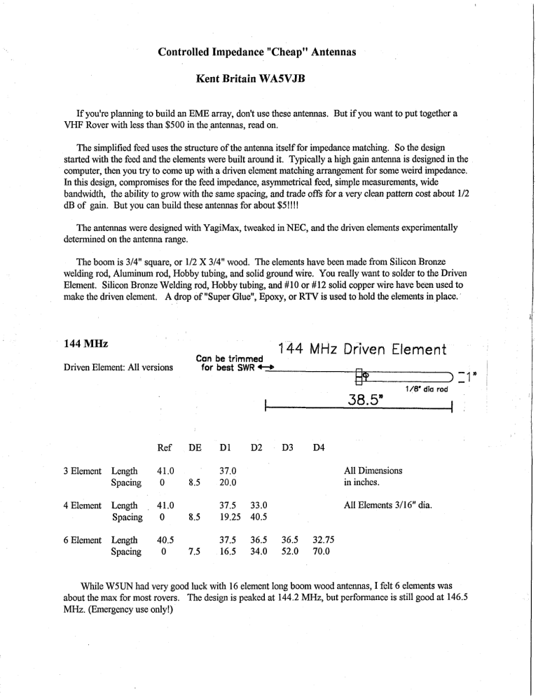
Controlled Impedance "Cheap"Antennas Kent Britain WASVJB If you're planning to build an EME array, don't use these antennas. But if you want to put together a VHF Rover with less than $500 in the .antennas, read on. The simplified feed uses the structure of the antenna itself for impedance matching. So the design started with the feed and the elements were built around it. Typically a high gain antenna is designed in the computer, then you try to come up with a driven element matching arrangement for some weird impedance. In this design, compromises for the feed impedance, asymmetrical feed, simple measurements, wide bandwidth, the ability to grow with the same spacing, and trade offs for a very clean pattern cost about 112 dB of gain. But you can build these antennas for about $5 !!!! The antennas were designed with YagiMax, tweaked in NEC, and the driven elements experimentally determined on the antenna range. The boom is 314" square, or 112 X 314" wood. The elements have been made from Silicon Bronze welding rod, Aluminum rod, Hobby tubing, and solid ground wire. You really want to solder to the Driven Element. Silicon Bronze Welding rod, Hobby tubing, and #10 or #12 solid copper wire have been used to make the driven element. A drop of "Super Glue", Epoxy, or RTV is used to hold the elements in place. 144 MHz Driven Element: All versions Can be trimmed for best SWR +B 144 MHz Driven Element dl I - 118' dia rod 11" Ref 3 Element Length Spacing 4 Element Length Spacing 6 Element Length Spacing , 41.0 0 All Dimensions in inches. 41.0 0 All Elements 3/16" dia. 40.5 0 While W5UN had very good luck with 16 element long boom wood antennas, I felt 6 elements was about the max for most rovers. The design is peaked at 144.2 MHz, but performance is still good at 146.5 MHz. (Emergency use only!) I 222 MHz This antenna is peaked at 222.1 MHz, but performance has barely changed at 223.5 MHz. Mine has the mounting holes drilled so I can mount it Horiz or Vert. Driven Element for all Versions: 222 MHz Driven Element nI:1 /8' dia rod I Ref ' 24.5" i I DE 3 Element Length Spacing 26.0 4 Element Length Spacing 26.25 0 5.0 6 Element Length Spacing 26.25 0 5.0 0 23.75 5.5 13.5 All Dimensions in Inches All Elements 3/16" dia 432 MHz At this band the antenna is getting very practical and easy to build. Elements are 118" diameter Driven Element for all versions: 432 MHz Driven Element Ref 6 Element Length Spacing 13.5 8 Element Length Spacing 13.5 11 Element Length Spacing 13.5 12.5 12.0 12.0 11.0 2.5 5.5 11.25 17.5 24.0 All dimensions in inches 9021903 MHz This was the first antenna I built using the antenna to control the driven element impedance. The 2 112 ft length has proven practical so I haven't build any other versions. 902 MHz Dirven Element Driven Element: I.5' #10 Copper Wire Ref Length Spacing 6.2 0 DE Dl D2 B3 D4 D5 D6 D7 D8 2.4 5.6 3.9 5.5 5.8 5.5 9.0 5.4 12.4 5.3 17.4 5.2 22.4 5.1 27.6 5.1 33.0 All dimensions in inches, elements 118" dia. 1296 MHz This antenna is the veteran of several "Grid Peditionst' and has measured 13.5 dBi on the CSVHFS antenna range. Dimensions must be followed with great care. The driven element is small enough to allow .I41 simi-rigid to be used instead of RG-58. I used 118" Silicon Bronze welding rod for the elements, but any 118" dia material can be used. 1 2 9 6 MHz Driven Element -! Driven Element 141 Semi Rigid Length Position 0 Ref DE Dl D2 D3 D4 D5 D6 D7 D8 4.3 1.7 3.9 4.0 3.8 6.3 3.75 8.7 3.75 12.2 3.65 15.6 3.6 19.3 3.6 23.0 3.5 2.8 All Dimensions in inches Note: I had been corresponding with KA9LNV about this design. Ed showed up with a copy of my antenna at the 1994 Central States VHF Society antenna contest. Ed won the 1296 MHz category, beating me by .2 dB with my own design! 435 MHz AMSAT I appreciate the help and motivation from KA9LNV for these antennas. N5EM even built an array of 16, 11 element versions of these antennas for Field Day. A high Front to Back ratio was a major design consideration of all versions. The computer predicts 30 dB FIB for the 6 element, and over 40 dB for the others. Using 314" square wood for the boom makes it easy to build two antennas on the same boom cross polarized. Offset the two antennas 6 112" and feed in pha'se for Circular Polarization. Or just use one for portable operations. AMSAT 435 MHz Driven Element 9 .5' Driven Element Ref Spacing 0 all versions , . I s DE 2.5 All Dimensions in inches. 6 Element length 13.4 12.4 12.0 12.0 11.0 8 Element length 13.4 12.4 12.0 12.0 12.0 12.0 11.1 10 Element length 13.4 12.4 12.0 12.0 12.0 12.0 11.75 11.75 11 Element length 13.4 12.4 12.0 12.0 12.0 12.0 11.75 11.1 11.75 11.75 11.1 NEC predicts 11.2 dBi for the 6 element, 12.6 dBi for the 8 element, and 13.5 for the 10 element, and 13.8 dBi for the 11 element. 450 MHz Yea, Yea, I understand, it's FM, but sometimes a newcomer needs a cheap antenna to get into a repeater or give you a simplex QSO during a contest. Radio Shack 118" dia Aluminum ground wire Catalog # 15035 was used in the prototype for all the elements except the Driven element. Other 118" dia material could be used. 450 MHz Driven Element Driven Element Ref Length Position 0 13.0 2.5 DE 5.5 Dl D2 12.1 11.0 11.75 11.75 10.75 All dimensions in 18.0 28.5 inches. D3 D4 75 Ohm Versions 421.25 MHz ATV 42 1 MHz Vestigial SideBand Video is popular in North Texas for receiving the FM video input repeaters. These antennas are made of 421 MHz use and the driven element is designed for 75 Ohms. So RG-59, or an 'F:,adapter to RG-6 can be directly connected to a-cable TV converterICable Ready TV on channel 57. 1 421 MHz 75 Ohm A N #I B Capper Wire / Driven Element:! I I I I I 6.25" I 6.25" 1IT I Ref 'DE Dl D2 Spacing 0 all versions 3.0 6.5 12.25 17.75 24.5 6 element length 14.0 12.5 12.25 12.25 11.0 9 element length 14.0 12.5 11 element length 14.0 12.5 D3 D4 D5 D6 D7 D8 ID9 30.5 36.0 43.0 50.25 57.25 12.25 12.25 12.0 12.0 11.25 12.25 12.25 12.0 12.0 12.0 11.75 11.75 11.5 Sliding a quarter wave sleeve along the coax had little effect, so there's not much RF on the outside of the coax. I've had a Polyurethane varnished 902 MHz version in the air for two years now with little deterioration. The life of the antenna is determined by what you coat it with. These antennas have been carefully designed to have the highest dB's/Dollar ratio of anythmg around. I recently saw a 20 Meter antenna with the dimensions specified in 1/10,000 thousands of an inch!! That guy needs to get real! A 1 degree change in temperature would change the lengths more than that! I kept dimensions to tenths of an inch to make these antennas easier to build. Finally a bit of history on the design of these antenna. In 1993 at Oklahoma City Central States VHF Society Arnie C02KK spoke on the difficulties building VHF antennas in non-industrialized nations. Sure, just run down to the store and pick up some Delrin Insulators and .I4 1 Teflon Coax??? Arnie's tales were the motivation to use advanced technology to come up with something simple. Stack of Prototypes: 1144 through 1296 MHz Driven Element Detail Solder the Coa Drive
