www.motorparts.it
Anuncio
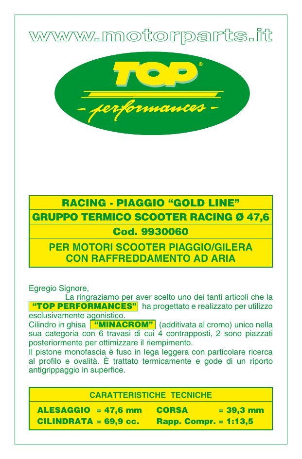
www.motorparts.it RACING - PIAGGIO “GOLD LINE” GRUPPO TERMICO SCOOTER RACING Ø 47,6 Cod. 9930060 PER MOTORI SCOOTER PIAGGIO/GILERA CON RAFFREDDAMENTO AD ARIA Egregio Signore, La ringraziamo per aver scelto uno dei tanti articoli che la “TOP PERFORMANCES” ha progettato e realizzato per utilizzo esclusivamente agonistico. Cilindro in ghisa “MlNACROM” (additivata al cromo) unico nella sua categoria con 6 travasi di cui 4 contrapposti, 2 sono piazzati posteriormente per ottimizzare il riempimento. Il pistone monofascia è fuso in lega leggera con particolare ricerca al profilo e ovalità. È trattato termicamente e gode di un riporto antigrippaggio in superfice. CARATTERISTICHE TECNICHE ALESAGGIO = 47,6 mm CILINDRATA= 69,9 cc. CORSA = 39,3 mm Rapp. Compr.= 1:13,5 IL KIT È COMPOSTO DA: 1) 1 2) 1 3) 4) 5) 6) 7) 8) 1 1 2 1 1 1 Cilindro Ø 47,6 mm in ghisa speciale “MINACROM” (addittivata al cromo) Pistone Ø 47,6 mm ad alto tenore di silicio con riporto antigrippaggio Segmento Ø 47,6 con riporto di cromo Spinotto pistone Ø 12 x 40 mm biconico Fermi spinotto pistone Testa Ø 47,6 Guarnizione base cilindro Guarnizione OR Ø 51,50 x 1,78 Viton ISTRUZIONI AL MONTAGGIO OPERAZIONI PRELIMINARI – Lavare accuratamente il veicolo, ed in modo particolare la parte motore interessata all’intervento. – Smontare marmitta, candela e convogliatori aria. – Svitare i dadi fissaggio testa. Smontare con cautela testa, cilindro e pistone. – Verificare le condizioni dell’imbiellaggio. Qualora non fosse in buono stato ne consigliamo la sostituzione con uno nuovo. – Controllare con attenzione che all’interno del nuovo cilindro (1) non vi siano delle impurità. Smussare con un raschietto tutte le luci di travaso presenti sulla canna del cilindro. Lavarlo con solvente idoneo e soffiarlo accuratamente. – Lavare con solvente idoneo e soffiare tutte le parti del kit per eliminare eventuali residui di lavorazione. – Proteggere con uno straccio pulito l’imbocco del carter motore, onde evitare che, accidentalmente vi entri dello sporco. Procedere con molta cura alla pulizia del piano d’appoggio del cilindro sul carter. MONTAGGIO CILINDRO E PISTONE – Inserire la gabbia a rulli nel piede di biella dopo averla lubrificata abbondantemente con olio miscela 100% sintetico. – Montare sul pistone (2) uno dei due fermi spinotto (5), lubrificare la cava segmento e montarvi il segmento con molta cura. Attenzione, ove presente, montare il segmento con la scritta “TOP” (ALTO) verso il cielo del pistone. Verificare che il segmento entri interamente 2 nella propria sede esercitando una leggera pressione con le dita, a conferma di un corretto montaggio del segmento stesso. – Montare il pistone (2) avendo cura che la freccia incisa sulla sommità dello stesso sia rivolta verso la luce di scarico del cilindro. Inserire, dal lato in cui non avete ancora montato il fermo, lo spinotto (4) ben lubrificato. – Montare il secondo fermo spinotto (5) assicurandovi che entrambi i fermi siano perfettamente alloggiati nelle proprie sedi in assenza completa di gioco fra fermo e relativa sede. – Inserire la guarnizione di base cilindro (7). – Lubrificare la canna del cilindro (precedentemente lavato e soffiato). – Posizionare l’apertura del segmento in corrispondenza dell’apposito fermo, comprimere all’interno della cava il segmento ed inserire dolcemente il cilindro ben lubrificato fino a battuta sulla guarnizione base. – Per sincerarsi che il montaggio sia avvenuto correttamente, far compiere manualmente al motore due o tre giri completi (tenendo fermo il cilindro con la mano libera). Verificare che il pistone non abbia interferito con nessuna parte del carter motore. Nel caso si sia verificata interferenza, asportare dal carter il materiale in eccesso avendo cura di proteggere l’imbocco dall’ingresso di materiale asportato e rimontare pistone e cilindro come descritto in precedenza. MONTAGGIO TESTA – Montare l’O-Ring (8) nella relativa sede sul piano testa (6) ed inserirla sui prigionieri fino a battuta col cilindro. Controllate che l’OR sia rimasto in sede. – Serrare i dadi della testa in modo incrociato e graduale con una coppia di serraggio 12±1 Nm (circa 1.2±0.1 kgm). – Montare la cuffia sul cilindro, il convogliatore e la NUOVA candela (vedi sezione “consigli importanti”). VALVOLA LAMELLARE – Accertatevi che la valvola lamellare sia in perfette condizioni. In ogni ca so si consiglia di sostituirla con la valvola TOP PERFORMANCES (cod. 9906520) con petali in fibra di carbonio, per risolvere i problemi di affidabilità che le aumentate prestazioni del motore darebbero. POMPA OLIO – Verificare che la pompa olio funzioni correttamente, che i tubi siano in buono stato e che non vi siano perdite. 3 – Per i modelli con pompa olio a portata variabile, controllare la taratura secondo le indicazioni del manuale di uso e manutenzione del veicolo. – Completare il montaggio del veicolo. RODAGGIO La fase di rodaggio è molto importante perché consente a tutte le nuove parti di adattarsi fra loro gradualmente. Non rispettare tale fase può causare danni o deformazioni anomale che porterebbero ad una perdita di potenza o ad un facile grippaggio. Consigliamo, quindi, di non usare il veicolo al massimo delle prestazioni per i primi 300 km. CONSIGLI IMPORTANTI – Per ristabilire l’equilibrio termico è indispensabile montare una candela nuova tipo NGK BR9EG o altre di pari grado termico. – Per poter sfruttare al meglio la potenza di cui disponete ora, la TOP PERFORMANCES ha provveduto a realizzare una serie di altri articoli determinanti, che è possibile trovare sul catalogo o consultando il sito www.motorparts.it. PARTI DI RICAMBIO Pistone completo Ø 47,6 Pistone completo maggiorato Ø 48 Serie segmenti Ø 47,6 Serie segmenti maggiorati Ø 48 Testa Serie guarnizioni 4 9930060 9913690 9913691 9913700 9913701 9930080 9914290 GARANZIA La garanzia si limita alla sostituzione delle parti riconosciute difettose da Motorparts S.p.A.. Per nessun motivo si deve montare un prodotto di nostra fabbricazione su veicoli ove non è indicata la compatibilità. La garanzia non viene riconosciuta nei seguenti casi: a) modifica o manomissione del prodotto; b) montaggio o utilizzo non corretti; c) sostituzione di alcune parti del kit con altre non Top Performances; d) utilizzo in condizioni anomale del prodotto. Immagini, dati e indicazioni tecniche contenuti in questo manuale non sono impegnative. La Motorparts S.p.A. si riserva di apportare, per aggiornamenti o migliorie, qualsiasi tipo di variazione anche senza preavviso. CONSIGLI Per il miglior rendimento del motore, Vi consigliamo di usare lubrificanti di qualità. • Stoccare l’olio motore usato in un contenitore dotato di tappo di chiusura. Non miscelare l’olio usato con altre sostanze come fluidi antigelo o di trasmissione. • Tenere lontano dalla portata dei bambini e da fonti di calore. • Portare l’olio usato presso un centro di smaltimento: la maggior parte delle stazioni di servizio, officine di riparazione e lubrificazione rapida ritirano gratuitamente gli oli esausti. • Si consiglia l’utilizzo di guanti resistenti agli idrocarburi. Per ulteriori dettagli e altre informazioni potete consultare il nostro sito www.motorparts.it 5 www.motorparts.it RACING - PIAGGIO “GOLD LINE” SCOOTER RACING PISTON-CYLINDER ASSY Ø 47.6 Part no. 9930060 FOR PIAGGIO/GILERA SCOOTER ENGINES WITH AIR COOLING SYSTEMS Dear Customer, Thank you for choosing one of the various items that “TOP PERFORMANCES” has designed and manufactured for competitive purposes only. The cylinder is made from special “MlNACROM” cast iron (with chrome added to the alloy), unique in its class, with 6 scavenge ports, 4 of them opposing ones and 2 are posteriorly placed to maximise filling. The single ring piston is cast in light alloy with particular attention to profile and oval shape. It undergoes a heat treatment and has an antiscuff facing in the surface. SPECIFICATIONS BORE = 47.6 mm STROKE = 39.3 mm DISPLACEMENT = 69.9 cc. Ratio Compr.= 1:13.5 6 THE KIT CONSISTS OF: 1) 1 2) 1 3) 4) 5) 6) 7) 8) 1 1 2 1 1 1 Cylinder Ø 47.6 mm in “MINACROM” cast iron (with chrome added to the alloy) Piston Ø 47.6 mm with high silicon content and antiscuff facing Piston ring Ø 47.6 with chrome facing Biconical piston gudgeon pin Ø 12 x 40 mm Gudgeon pin circlips Head Ø 47.6 Cylinder base gasket Viton O-ring Ø 51.50 x 1.78 ASSEMBLY INSTRUCTIONS PRELIMINARY OPERATIONS – Carefully wash the vehicle, specially the engine part installation area. – Remove muffler, spark plug and air routers. – Loosen the head nuts. Carefully remove head, cylinder and piston. – Check connecting rods. If not in good conditions, we would recommend to replace it with new one. – Carefully check that inside the new cylinder (1) there is no foreign matter. With a scraper, bevel all transfer ports on the cylinder barrel. Wash it with suitable solvent and blow with air. – Wash with suitable solvent and blow all parts in the kit to eliminate any possible machining residues. – Use a clean rag to protect the crankcase opening so as to avoid foreign matter from accidentally entering. Carefully proceed to cleaning the mating surface of cylinder with crankcase. CYLINDER AND PISTON ASSEMBLY – Fit the roller cage in the con-rod small end after having abundantly lubricated it with fully synthetic mixer oil. – Fit one of the two gudgeon pin circlips (5) on the piston (2), lubricate the piston ring groove and carefully fit the piston ring. If present, be careful to fit the piston ring with the inscription “TOP” towards the piston crown. Check that the piston ring enters completely into its seat slightly pressing with the fingers to confirm a correct assembly. 7 – Fit the piston (2) ensuring that the arrow at the top points to the cylinder exhaust port. Fit the lubricated gudgeon pin (4) from the side with no circlip. – Fit the second gudgeon pin circlip (5) and check for both of them being correctly positioned in their seats, without any clearance between them and their seats. – Fit the cylinder base gasket (7). – Lubricate the cylinder barrel (already washed and blown with air). – Position the gudgeon pin circlip opening at the suitable retainer, push the gudgeon pin circlip inside the groove and carefully insert the lubricated cylinder fully home on the base gasket. – Manually turn the crankshaft two or three times (holding the cylinder with your free hand) to ensure engine is correctly assembled. Check that the piston does not interfere with any part of the engine crankcase. In case of interference, remove excess material from the crankcase while protecting the opening from removed material and refit piston and cylinder as previously described. HEAD ASSEMBLY – Fit the O-Ring (8) in its seat on the head surface (6) and insert it in the stud bolts until fully home on the cylinder. Check that the O-Ring is in its seat. – Tighten the head nuts in a cross pattern and in several steps to a torque of 12±1 Nm (approx.1.2±0.1 kgm). – Fit cover on the cylinder, the air conveyor, and the NEW spark plug (see section “Important notes”). REED VALVE – Make sure the reed valve is in perfect conditions. Anyway, it is recommended to replace it with the TOP PERFORMANCES valve (part no. 9906520) with carbon fibre flaps, to solve reliability problems that increased engine power may cause. OIL PUMP – Check the correct operation of the oil pump, that hoses are in good conditions and that there are no leaks. – For models with variable-displacement oil pumps, check calibration according to the indications in the vehicle use and maintenance handbook. – Complete the vehicle assembly. 8 RUNNING-IN Running-in is very important because it allows all the new parts to gradually settle. Failure to follow the rules set for the running-in period could cause damages or strange deformations that would lead to loss of power or likely seizure. We therefore recommend to avoid using the vehicle at its maximum power for the first 300 km. IMPORTANT NOTES – To restore heat rating, it is important to fit a new spark plug of the type NGK BR9EG or another one having the same heat rating. – To take advantage of the power available for you now, TOP PERFORMANCES has provided to make a number of other decisive articles, which can be found on the catalogue or visiting the web-page www.motorparts.it. SPARE PARTS Complete piston Ø 47.6 Oversized complete piston Ø 48 Set of piston rings Ø 47.6 Set of oversized piston rings Ø 48 Head Standard gaskets 9 9930060 9913690 9913691 9913700 9913701 9930080 9914290 WARRANTY Warranty is limited to the replacement of parts recognised as faulty by Motorparts S.p.A.. Our products should never be fitted to a vehicle for which compatibility is not indicated. Warranty does not cover: a) changes or tampering with the product; b) incorrect assembly or use; c) replacement of kit parts with parts not Top Performances; d) use of the product in non-standard conditions. Pictures, data and specifications given in this manual are not binding. Motorparts S.p.A. reserves the right to make changes for any reason whatsoever, be it for update or improvement, even without notice. TIPS To ensure the best engine performance, we recommend using highquality lubricants. • Store used engine oil in a vessel with sealing cap. Do not mix used oil with any other substance such as antifreeze or transmission fluids. • Keep away from children and any heat source. • Bring used oil to an authorised waste disposal company: most service stations, repair and quick-lubrication garages usually take in used oil for free. • We recommend using hydrocarbon-resistant gloves. For more information visit our website www.motorparts.it 10 www.motorparts.it RACING - PIAGGIO “GOLD LINE” ENSEMBLE THERMIQUE SCOOTER RACING Ø 47,6 Réf. 9930060 POUR MOTEURS SCOOTER PIAGGIO/GILERA AVEC SYSTÈME DE REFROIDISSEMENT À AIR Cher Client, Nous vous remercions d'avoir choisi l'un des nombreux articles que “TOP PERFORMANCES” a conçu et réalisé pour une utilisation exclusive en compétition. Cylindre en fonte “MlNACROM” (adjuvé avec du chrome) unique dans sa catégorie avec 6 transvasements dont 4 opposés, 2 sont placés à l'arrière pour optimiser le remplissage. Le piston mono-segment est fondu en alliage léger avec une attention particulière pour son aspect profilé et ovale. Il est traité thermiquement et est doté d'une couche antigrippage en surface. CARACTERISTIQUES TECHNIQUES ALÉSAGE = 47,6 mm CYLINDRÉE = 69,9 cc. COURSE = 39,3 mm Rapp. Compr.= 1:13,5 11 LE KIT SE COMPOSE DE : 1) 1 2) 1 3) 4) 5) 6) 7) 8) 1 1 2 1 1 1 Cylindre Ø 47,6 mm en fonte spéciale “MINACROM” (adjuvée avec du chrome) Piston Ø 47,6 mm à haute teneur en silicium avec couche antigrippage Segment Ø 47,6 revêtu au chrome Axe de piston Ø 12 x 40 mm biconique Jonc d'arrêt axe de piston Culasse Ø 47,6 Joint d'embase cylindre Joint OR Ø 51,50 x 1,78 Viton INSTRUCTIONS DE MONTAGE OPÉRATIONS PRÉLIMINAIRES – Nettoyer soigneusement le véhicule, et en particulier la partie moteur concernée par l’intervention. – Déposer le pot d’échappement, la bougie et les déflecteurs d’air. – Desserrer les écrous de fixation de la culasse. Déposer délicatement la culasse, le cylindre et le piston. – Vérifier l’état de l’embiellage. S’il n’est pas en bon état, il est conseillé de le remplacer. – Contrôler attentivement l’absence d’impuretés à l’intérieur du nouveau cylindre (1). Arrondir avec un racloir toutes les ouvertures de transvasement présentes sur le conduit du cylindre. Laver le cylindre avec un solvant approprié et le souffler soigneusement. – Laver avec un solvant approprié et souffler toutes les pièces du kit pour éliminer tout résidu d’usinage. – Protéger avec un chiffon propre l’entrée du carter moteur, pour éviter que des saletés y pénètrent accidentellement. Procéder au nettoyage minutieux du plan d’appui du cylindre au niveau du carter. MONTAGE CYLINDRE ET PISTON – Insérer la cage à rouleaux dans le pied de bielle après l’avoir lubrifiée abondamment avec un mélange d’huiles 100% synthétique. – Monter sur le piston (2) un des deux joncs de l’axe (5), lubrifier la gorge du segment et y poser le segment en faisant très attention. Attention : monter le segment avec l’inscription “TOP” (HAUT), là où elle est présente, en direction de la calotte du piston. Vérifier que le segment entre entièrement dans l’espace prévu à cet effet 12 en exerçant une légère pression avec les doigts, pour vérifier que le montage dudit segment a été correctement effectué. – Monter le piston (2) en veillant à ce que la flèche gravée sur la calotte soit tournée vers le côté échappement du cylindre. Introduire l’axe de piston (4) bien graissé du côté où on n’a pas encore monté le jonc d’arrêt. – Monter le second jonc de l’axe du piston (5) en s’assurant que les deux joncs sont parfaitement posés en absence complète de jeu entre jonc et siège. – Insérer le joint d’embase (7). – Graisser le corps du cylindre (préalablement lavé et soufflé). – Positionner l’ouverture du segment en correspondance du jonc correspondant, comprimer le segment à l’intérieur de la rainure et insérer doucement le cylindre dûment lubrifié en butée contre le joint d’embase. – Pour s’assurer du montage correct, réaliser manuellement deux ou trois tours complets du moteur (en immobilisant le cylindre d’une main laissée libre). Vérifier que le piston n’a pas interféré avec aucune partie du carter moteur. S’il y a eu une interférence, enlever du carter le matériau en excès en prenant soin de protéger l’ouverture pour éviter l’entrée des matériaux enlevés et remonter le piston et le cylindre comme décrit précédemment. MONTAGE CULASSE – Monter le joint torique (8) dans la zone correspondante au niveau du plan de la culasse (6) et l’insérer sur les goujons en butée contre le cylindre. Contrôler que le joint torique n’a pas bougé. – Serrer les écrous de la culasse suivant un parcours croisé et de manière progressive en y appliquant un couple de 12±1 Nm (environ 1.2±0.1 kgm). – Monter le soufflet sur le cylindre, le déflecteur d’air et la NOUVELLE bougie (voire section “Conseils Importants”). SOUPAPE À CLAPET – S’assurer que la soupape à clapet est en bon état. En tout cas, nous conseillons de la remplacer par la soupape TOP PERFORMANCES (réf. 9906520) avec des pétales en fibre de carbone, pour résoudre les problèmes de fiabilité que des performances plus importantes du moteur pourraient causer. POMPE HUILE – Vérifier que la pompe à huile fonctionne correctement, que les tuyaux sont en bon état et qu’il n’y a pas de fuites. 13 – Pour les modèles avec une pompe à huile à débit variable, contrôler le réglage en suivant les indications du manuel d’utilisation et d’entretien du véhicule. – Terminer le montage du véhicule. RODAGE La période de rodage est très importante car elle permet à toutes les pièces neuves de se mettre progressivement en place les unes par rapport aux autres. Le non-respect de cette période de rodage peut provoquer des dégâts ou des déformations anormales susceptibles d'entraîner une perte de puissance ou favoriser le grippage. Il est donc conseillé de ne pas conduire le véhicule au maximum de ses performances pendant les 300 premiers Km. CONSEILS IMPORTANTS – Pour rétablir l'équilibre thermique il est indispensable de monter une nouvelle bougie type NGK BR9EG ou d'autre type ayant le même degré thermique. – Pour pouvoir exploiter au mieux la puissance dont vous disposez maintenant, TOP PERFORMANCES a réalisé une série d'autres articles importants, disponibles sur le catalogue ou en consultant le site www.motorparts.it. PIÈCES DÉTACHÉES 9930060 9913690 9913691 9913700 9913701 9930080 9914290 Piston complet Ø 47,6 Piston complet majoré Ø 48 Jeu de segments Ø 47,6 Jeu de segments majorés Ø 48 Té Jeu de joints 14 GARANTIE La garantie est limitée au remplacement des pièces reconnues comme étant défectueuses par Motorparts S.p.A.. Il ne faut en aucun cas monter un produit de notre fabrication sur des véhicules où la compatibilité n’est pas indiquée. La garantie ne couvre pas : a) a modification ou l’altération du produit; b) le montage ou l’utilisation incorrect; c) le remplacement de pièces du kit par d’autres pièces qui ne sont pas Top Performances; d) l’utilisation du produit dans des conditions non standard. Les photos, les données et les indications techniques contenues dans ce manuel n’engagent à rien. Motorparts S.p.A. se réserve la faculté d’apporter, pour des mises à jour ou des améliorations, tout type de variation même sans préavis. CONSEILS Pour une performance optimale du moteur, nous Vous conseillons d’utiliser des lubrifiants de qualité. • Stocker l’huile moteur usagée dans un conteneur pourvu de bouchon de fermeture. Ne pas mélanger l’huile usagée avec d’autres fluides antigel ou de transmission. • Conserver hors de la portée des enfants et à l’écart des sources de chaleur. • Porter l’huile usagée auprès d’un centre préposé à l’évacuation : la plupart des stations-service, des ateliers de réparation et de graissage rapide retirent les huiles usagées à titre gratuit. • Il est recommandé d’utiliser des gants de protection contre les hydrocarbures. Pour plus de détails et d’informations consultez notre site www.motorparts.it 15 www.motorparts.it RACING - PIAGGIO “GOLD LINE” GRUPO TÉRMICO SCOOTER RACING Ø 47,6 Cód. 9930060 PARA MOTORES SCOOTER PIAGGIO/GILERA REFRIGERADOS POR AIRE Estimado Señor: Le agradecemos por haber elegido uno de los varios artículos que “TOP PERFORMANCES” ha diseñado y realizado para uso exclusivamente agonístico. Cilindro de hierro fundido “MlNACROM” (con aditivo de cromo) único en su categoría con 6 transvases de los cuales 4 contrapuestos, 2 colocados en la parte trasera para optimizar el llenado. El pistón con un anillo está fundido en aleación ligera considerando su perfil y su forma ovalada. Está tratado térmicamente y en la superficie cuenta con un revestimiento contra el agarrotamiento. CARACTERÍSTICAS TÉCNICAS DIÁM. INT. = 47,6 mm CARRERA = 39,3 mm CILINDRADA= 69,9 cc. Relac. de Compr.= 1:13,5 16 EL KIT ESTÁ COMPUESTO POR: 1) 1 2) 1 3) 4) 5) 6) 7) 8) 1 1 2 1 1 1 Cilindro Ø 47,6 mm de hierro fundido especial “MINACROM” (con aditivo de cromo) Pistón Ø 47,6 mm con alto tenor de silicio revestido contra el agarrotamiento Segmento Ø 47,6 con revestimiento de cromo Bulón del pistón Ø 12 x 40 mm bicónico Seguros bulón del pistón Culata Ø 47,6 Junta base cilindro Junta tórica Ø 51,50 x 1,78 Viton INSTRUCCIONES DE MONTAJE OPERACIONES PRELIMINARES – Lavar perfectamente el vehículo, especialmente la parte donde se realizará la intervención. – Desmontar el silenciador, la bujía y los encanaladores de aire. – Desatornillar las tuercas que fijan la culata. Desmontar con cautela la culata, el cilindro y el pistón. – Verificar las condiciones del acoplamiento de bielas. Si no estuviera en buen estado, recomendamos sustituirlo con uno nuevo. – Controlar con atención que dentro al nuevo cilindro (1) no se encuentren impurezas. Con un raspador, redondear todas las luces de transferencia presentes en el cañón del cilindro. Lavarlo con disolvente adecuado y soplarlo cuidadosamente. – Lavar con disolvente adecuado y soplar todas las partes del kit para eliminar eventuales residuos de elaboración. – Proteger con un paño limpio la embocadura del cárter motor para evitar que accidentalmente entre suciedad. Limpiar con mucho cuidado la superficie de apoyo del cilindro en el cárter. 17 MONTAJE CILINDRO Y PISTÓN – Introducir la jaula de agujas en el pie de biela tras haberla lubrificado con abundante aceite mezcla 100% sintético. – Montar uno de los dos seguros bulón (5) en el pistón (2), lubricar el alojamiento del segmento y montar el segmento con mucho cuidado. Atención, cuando esté presente, montar el segmento con la inscripción “TOP” (ARRIBA) hacia la cabeza del pistón.Verificar que el segmento entre completamente en su alojamientos presionando levemente con los dedos y confirmar su correcto montaje. – Montar el pistón (2) controlando que la flecha en la parte superior esté dirigida hacia la luz de escape del cilindro. Desde el lado en que no se ha montado el seguro, montar el pistón (4) bien lubricado. – Montar el segundo bloqueo bulón (5) asegurándose de que ambos bloqueos se encuentren perfectamente introducidos en sus alojamientos y que no exista juego alguno. – Introducir la junta base cilindro (7). – Lubricar el cañón del cilindro (previamente lavado y soplado). – Colocar la abertura del segmento en correspondencia con el seguro específico, comprimir el segmento dentro del alojamiento e introducir suavemente el cilindro perfectamente lubricado a tope en la junta de base. – Para asegurarse de que el montaje sea correcto, hacer girar dos o tres veces el motor (sosteniendo el cilindro con la mano libre). Verificar que el pistón no interfiera con ninguna parte del cárter motor. En caso de interferencias, quitar el material en exceso del cárter teniendo cuidado de proteger la embocadura y volver a montar el pistón y el cilindro como descrito anteriormente. MONTAJE CULATA – Montar la junta tórica (8) en el relativo alojamiento sobre la superficie de la culata (6) e introducirla en los espárragos a tope con el cilindro. Controlar que la junta tórica esté en su alojamiento. – Ajustar las tuercas de la culata en modo cruzado y gradual con un par de apriete de 12±1 Nm (aproximadamente 1.2±0.1 kgm). – Montar el protector que envuelve el cilindro, el encanalador y la NUEVA bujía (ver sección “Recomendaciones Importantes”). VÁLVULA LAMINAR – Asegurarse de que la válvula laminar se encuentre en perfectas condiciones. De todos modos, se recomienda sustituir con la válvula TOP PERFORMANCES (cód. 9906520) con pétalos de 18 fibra de carbono, para resolver los problemas de confiabilidad que se presentarán en caso de aumento de prestaciones. BOMBA ACEITE – Verificar que la bomba de aceite funcione correctamente, que los tubos estén en buen estado y que no haya pérdidas. – Para los modelos con bomba de aceite a caudal variable, controlar la calibración según las indicaciones en el manual de uso y mantenimiento del vehículo. – Completar el montaje del vehículo. RODAJE La fase de rodaje es muy importante porque permite que todas las partes nuevas se amolden entre ellas de manera gradual. Si no se respeta dicha fase se podrían ocasionar daños o deformaciones anormales que podrían llevar a una pérdida de potencia o a un agarrotamiento. Por lo tanto recomendamos no usar el vehículo al máximo de sus prestaciones durante los primeros 300 km. RECOMENDACIONES IMPORTANTES – Para restablecer el equilibrio térmico es indispensable montar una bujía nueva tipo NGK BR9EG u otras con un grado térmico equivalente. – Para disfrutar al máximo de la potencia que ahora dispone, TOP PERFORMANCES ha realizado una serie de artículos determinantes, que se encuentran en el catálogo o consultando el sitio www.motorparts.it. 19 PARTES DE RECAMBIO Pistón completo Ø 47,6 Pistón completo aumentado Ø 48 Serie segmentos Ø 47,6 Serie segmentos aumentados Ø 48 Culata Serie juntas 9930060 9913690 9913691 9913700 9913701 9930080 9914290 GARANTÍA La garantía se limita a la sustitución de las partes reconocidas como defectuosas por Motorparts S.p.A.. Por ningún motivo se debe montar un producto de nuestra fabricación en vehículos donde no se indica la compatibilidad. La garantía no se aplica en los siguientes casos: a) modificación o manumisión del producto; b) montaje o uso incorrectos; c)sustitución de algunas partes del kit con otras no Top Performances; d) uso en condiciones anormales del producto. Las imágenes, datos e indicaciones técnicas contenidas en este manual son a titulo indicativo. Motorparts S.p.A. se reserva de aportar, para actualizar o mejorar, cualquier tipo de variación incluso sin preaviso. 20 RECOMENDACIONES Para un mejor rendimiento del motor, recomendamos utilizar lubrificantes de buena calidad. • Almacenar el aceite motor utilizado en un contenedor con tapón de cierre. No mezclar el aceite usado con otras sustancias, como fluidos antihielo o de transmisión. • Mantener fuera del alcance de los niños y lejos de fuentes de calor. • Llevar el aceite usado a un centro de reciclaje: la mayoría de las estaciones de servicio, talleres de reparación y de lubricación rápida lo retiran de manera gratuita. • Se recomienda el uso de guantes resistentes a los hidrocarburos. Para obtener mayores detalles e información puede visitar nuestro sitio www.motorparts.it 21 www.motorparts.it RACING - PIAGGIO „GOLD LINE” SCOOTER ZYLINDEREINHEIT RACING Ø 47,6 Art.-Nr. 9930060 FÜR MOTOREN SCOOTER PIAGGIO/GILERA MIT LUFTKÜHLUNG Sehr geehrte Damen und Herren, wir danken Ihnen, dass Sie einen der zahlreichen Artikel gewählt haben, welche „TOP PERFORMANCES” ausschließlich für den Wettkampfeinsatz entworfen und realisiert hat. Zylinder aus Gusseisen „MlNACROM” (mit Chromzusatz). Einzigartig in seiner Kategorie mit 6 Überläufen, von den 4 gegenüber liegen, 2 befinden sich dahinter, um die Befüllung zu optimieren. Der Kolben mit einem Kolbenring ist aus Leichtmetalllegierung gefertigt, wobei ein besonderes Augenmerk auf das Profil und die Ovalisierung gelegt wird. Er Ist wärmebehandelt und weist einen Einfressschutz an der Oberfläche auf. TECHNISCHE EIGENSCHAFTEN BOHRUNG = 47,6 mm HUB = 39,3 mm HUBRAUM = 69,9 ccm. Verdicht. verh. = 1:13,5 22 DAS KIT BESTEHT AUS: 1) 1 Zylinder Ø 47,6 mm aus „Minacrom” Spezialgusseisen (mit Chromzusatz) 2) 1 Kolben Ø 47,6 mm mit hohem Siliziumgehalt und Einfresschutz-Beschichtung. 3) 1 Kolbenring Ø 47,6 mm mit Chrombeschichtung 4) 1 Kolbenbolzen Ø 12 x 40 mm, doppelkonisch 5)2 Kolbenbolzensprengringe 6) 1 Zylinderkopf Ø 47,6 7)1 Zylinderfußdichtung 8) 1 O-Ring Ø 51,50 x 1,78 Viton MONTAGEANLEITUNG VORBEREITUNG – Das Fahrzeug sorgfältig waschen, insbesondere den Motorteil, der vom Eingriff betroffen ist. – Den Auspuff, die Zündkerze und die Luftleitkanäle ausbauen. – Die Zylinderkopfbefestigungsschrauben lösen. Den Zylinderkopf sowie Zylinder und Kolben vorsichtig ausbauen. – Den Zustand des Pleuelgestänges überprüfen. Sollte es beschädigt sein, empfehlen wir den Ersatz durch ein neues. – Aufmerksam überprüfen, dass im neuen Zylinder (1) keine Verschmutzungen vorhanden sind. Mit einem Schaber alle Überströmkanäle auf der Zylinderlaufbuchse abfasen. Mit geeignetem Lösemittel waschen und gründlich abblasen. – Alle Teile des Kits mit geeignetem Lösemittel waschen und abblasen und dabei eventuelle Rückstände Bearbeitungsrückstände beseitigen. – Mit einem sauberen Tuch die Öffnung des Kurbelgehäuses schützen, um zu vermeiden, dass versehentlich Schmutz eindringen kann. Mit großer Sorgfalt die Auflagefläche des Zylinders am Kurbelgehäuse reinigen. 23 MONTAGE VON ZYLINDER UND KOLBEN – Den Nadelkäfig nach ausgiebigem Schmieren mit einem 100 % Synthetikölgemisch den Pleuelkopf einfügen. – Einen der beiden Sprengringe (5) der Kolbenbolzen (2) montieren, die Kolbenringnut schmieren und den Kolbenring sorgfältig montieren. Achtung! Wo vorhanden, den Kolbenring mit der Aufschrift „TOP” (OBEN) zum Kolbenboden gerichtet montieren. Durch leichtes Andrücken mit den Fingern überprüfen, dass sich der Kolbenring vollständig in seinen Sitz eingefügt hat, was als Bestätigung ihrer korrekten Montage zu verstehen ist. – Den Kolben (2) montieren und darauf achten, dass der auf seinem Scheitel eingravierte Pfeil zum Auslass des Zylinders gerichtet ist. Den gut geschmierten Kolbenbolzen (4) von der Seite her, an der noch kein Sprengring montiert wurde, einfügen. – Den zweiten Sprengring (5) des Kolbenbolzens montieren und sich darüber vergewissern, dass beide Sprengringe sich perfekt in ihre Sitze eingefügt haben, ohne dass dabei ein Spiel zwischen dem Sprengring und seinem Sitz verbleibt. – Die Zylinderfußdichtung (7) einfügen. – Die (zuvor gewaschene und ausgeblasene) Zylinderlaufbuchse schmieren. – Die Öffnung des Kolbenrings an den vorgesehenen Anlaufstellen ausrichten, dann den Kolbenring in der Nut komprimieren und den gut geschmierten Zylinder sanft bis auf Anschlag an der Zylinderfußdichtung einfügen. – Sicherstellen, dass die Montage korrekt erfolgt ist, dann die Kurbelwelle von Hand um zwei oder drei vollständige Umdrehungen weiter drehen (dabei den Zylinder mit der freien Hand festhalten). Überprüfen, dass der Kolben an keinem Bereich des Motorgehäuses anläuft. Im Falle einer Interferenz das überschüssige Material vom Gehäuse abtragen, wobei darauf zu achten ist, dass die Öffnung vor dem Eindringen des entfernten Materials geschützt wird. Schließlich den Kolben und den Zylinder wie vorstehend beschrieben wieder montieren. MONTAGE DES ZYLINDERKOPFS – Den O-Ring (8) in seinem Sitz an der Zylinderkopffläche (6) montieren und bis auf Anschlag am Zylinder auf die Stiftschrauben fügen. Kontrollieren, dass der O-Ring in seinem Sitz geblieben ist. – Die Muttern des Zylinderkopfs über Kreuz und schrittweise mit einem Anzugsmoment von 12 ±1 Nm (circa 1,2 ± 0,1 kgm) anziehen. – Die Haube, den Luftleitkanal und die NEUE Zündkerze (siehe Abschnitt „Wichtige Empfehlungen”) auf dem Zylinder montieren. 24 LAMELLENVENTIL – Sicherstellen, dass sich das Lamellenventil im perfekten Zustand befindet. Auf jeden Fall wird jedoch ein Ersatz durch das Ventil TOP PERFORMANCES (Art.-Nr. 9906520) mit Lamellen aus Kohlefaser empfohlen, um Zuverlässigkeitsprobleme zu beheben, die sich bei den so erhöhten Leistungen am Motor ergeben könnten. ÖLPUMPE – Überprüfen, dass die Ölpumpe korrekt funktioniert und dass sich die Leitungen in einem guten Zustand befinden und keine Leckagen aufweisen. – Bei den Ölpumpen mit variablem Durchsatz die Einstellung den Angaben in der Betriebs- und Instandhaltungsanleitung des Fahrzeugs gemäß kontrollieren. – Die Montage des Fahrzeugs vervollständigen. EINLAUFPHASE Die Einlaufphase ist sehr wichtig, da sie es allen neuenTeilen ermöglicht, sich graduell aufeinander anzupassen. Eine Nichteinhaltung dieser Phase kann zu Schäden oder anormalen Verformungen führen, die einen Leistungsverlust oder ein schnelles Einfressen verursachen könnten. Wir empfehlen daher das betreffende Fahrzeug auf den ersten 300 km nicht mit Höchstgeschwindigkeit zu fahren. WICHTIGE EMPFEHLUNGEN – Zum erneuten Herstellen des thermischen Gleichgewichts muss unbedingt eine neue Zündkerze vom Typ NGK BR9EG oder andere mit demselben Wärmegrad montiert werden. – Um die nun zur Verfügung stehende Leistung noch besser nutzen zu können, hat TOP PERFORMANCES weitere, dafür ausschlaggebende Artikel entwickelt, die Sie im Katalog oder in der Website www.motorparts.it finden können. 25 ERSATZTEILE Kompletter Kolben Ø 47,6 Kompletter, vergrößerter Kolben Ø 48 Satz Kolbenringe Ø 47,6 Satz vergrößerte Kolbenringe Ø 48 Zylinderkopf Dichtungssatz 9930060 9913690 9913691 9913700 9913701 9930080 9914290 GARANTIE Die Garantie beschränkt sich auf den Ersatz von Teilen, deren Defekt durch Motorparts S.p.A. anerkannt wurde.Es darf unter keinen Umständen ein von uns hergestelltes Produkt an Fahrzeugen verbaut werden, dessen Kompatibilität nicht angegeben ist. Die Garantie wird in folgenden Fällen nicht anerkannt: a) Umänderung oder Handhabung des Produktes; b) unsachgemässe/r Montage oder Gebrauch; c) Ersatz von Teilen des Kits durch Produkte, die nicht von Top Performances stammen; d) Gebrauch des Produktes unter nicht vorgesehenen Bedingungen. Die in diesem Handbuch enthaltenen Bilder, Daten und technischen Angaben sind unverbindlich. Die Motorparts S.p.A. behält sich das Recht vor, Neuerungen oder Verbesserungen jeglicher Art, auch ohne vorangehende Ankündigung, vorzunehmen. 26 EMPFEHLUNGEN Um die maximale Motorleistung zu erreichen, empfehlen wir hochwertige Schmiermittel zu verwenden. • Das verbrauchte Motoröl in einem verschließbaren Behälter sammeln. Das Altöl nicht mit anderen Substanzen wie Frostschutzmittel oder Getriebeflüssigkeiten mischen. • Ausserhalb der Reichweite von Kindern und nicht in der Nähe von Hitzequellen lagern. • Das Altöl in ein Entsorgungszentrum bringen: die meisten Tankstellen, Reparatur- und Schnellservicewerkstätten nehmen Altöl kostenlos entgegen. • WirempfehlenHandschuhezuverwenden,diegegenKohlenwasserstoff resistent sind. WeitereDetails und InformationenfindenSieaufunsererWebseite www.motorparts.it 27 LI9930060 (11732) Distribuito da MOTORPARTS S.p.A. Gruppo Minarelli Finanziaria S.p.A. 40012 Lippo di Calderara di Reno (BO) Via Aldina, 26 - Fax ++39/051725449 http://www.motor par ts.it
