Estimación de las derivadas de Estabilidad Lateral
Anuncio
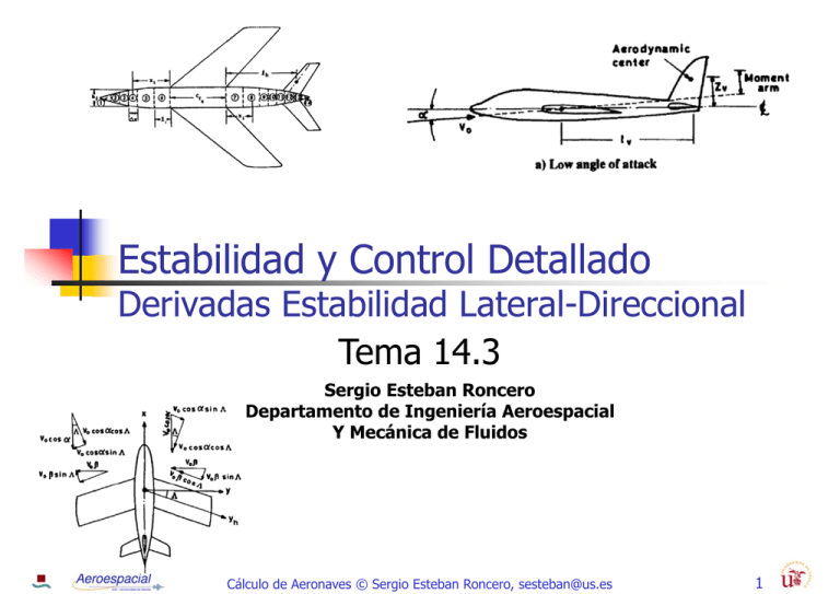
Estabilidad y Control Detallado Derivadas Estabilidad Lateral-Direccional Tema 14.3 Sergio Esteban Roncero Departamento de Ingeniería Aeroespacial Y Mecánica de Fluidos Cálculo de Aeronaves © Sergio Esteban Roncero, [email protected] 1 Derivadas Sideslip Derivatives Cálculo de Aeronaves © Sergio Esteban Roncero, [email protected] 2 Estimación Derivadas Contribución Contribución Ala: flecha, diedro Vertical Fuselaje Ala: flecha, diedro Vertical Canard/horizontal/V-tail Fuselaje Contribución , Ala: flecha, diedro Vertical Fuselaje Contribución Contribución Derivadas en 1/rad si no se indica lo contrario Si las derivadas no están en 1/rad hay que convertirlas Cálculo de Aeronaves © Sergio Esteban Roncero, [email protected] 3 Estabilidad Direccional Criterio Estabilidad Direccional Cálculo de Aeronaves © Sergio Esteban Roncero, [email protected] 4 Estabilidad Lateral Criterio Estabilidad Lateral Cálculo de Aeronaves © Sergio Esteban Roncero, [email protected] 5 Lateral-Directional Método I Contribución total ala vertical fuselaje Wing contribution AR – alargamiento ala Λ – flecha ala aproximación 1/rad Ref: Smetana Cálculo de Aeronaves © Sergio Esteban Roncero, [email protected] 6 Lateral-Directional Método I fuselage contribution Body Reference Area = fuselage volume - wing-fuselage interference factor / Ref: Smetana Fig A5 Fig B6 Cálculo de Aeronaves © Sergio Esteban Roncero, [email protected] 7 CL,f Ref: Smetana Fig A5 El CL del fuselaje se obtiene determinando el punto del fuselaje donde el flujo deja de ser potencial (x0) el cual se determina en función de x1 que es el punto del fuselaje donde la variación del fuselaje alcanza un Fig A6 mínimo en la variación de área, es decir cuando el fuselaje deja de aumentar Cálculo de Aeronaves © Sergio Esteban Roncero, [email protected] 8 Fig A5 Ref: Smetana (Fig 6) Cálculo de Aeronaves © Sergio Esteban Roncero, [email protected] 9 Fig A6 Ref: Smetana (Fig 7) Cálculo de Aeronaves © Sergio Esteban Roncero, [email protected] 10 Fig B6 Ref: Smetana (Fig 23) d = maximum body height at wing-body intersection = distance from body centerline to quarter-chord point of exposed wing root chord (positive for the quarter-chord point below the body centerline) , Cálculo de Aeronaves © Sergio Esteban Roncero, [email protected] 11 Lateral-Directional Método I = Ref: Pamadi Fig B5 Cálculo de Aeronaves © Sergio Esteban Roncero, [email protected] 12 Lateral-Directional Método Alternativo Cálculo completo (Smetana) ala-fuselaje Ref: Smetana ala vertical Método I No diedro ala-vertical Contribución ala Fig B15 Fig B14 Cálculo de Aeronaves © Sergio Esteban Roncero, [email protected] 13 Fig B14 Hay que convertir a . Como a se multiplica por el diedro en grados: Γ Γx tiene unidades , una vez que Γ y se corrige a radianes 180 Ref: Smetana Smetana (Fig 26) Cálculo de Aeronaves © Sergio Esteban Roncero, [email protected] 14 Fig B15 Corrección en función de la terminación de la punta del ala Ref: Smetana Smetana (Fig 25) Cálculo de Aeronaves © Sergio Esteban Roncero, [email protected] 15 Lateral-Directional Método I Alternative method A theoretical study for unswept ,elliptical wings with zero dihedral (NASA TR-1269) o – estrechamiento y AR – Alargamiento ala Contribución vertical Contribución ubicación ala Ref: Smetana Cálculo de Aeronaves © Sergio Esteban Roncero, [email protected] 16 Contribución Ala - I horizontal ala vertical V-tail Método II canard Contribución canard,horizontal y V-tail muy pequeñas → despreciable en 1ª aproximación Aproximación subsonic speeds Asegurarse que las unidades finales son 1/rad is the theoretical wing aspect ratio, is the average fuselage diameter at the wing root, is the wing span, is vertical distance between the fuselage centerline and wing root quarter chord point, positive if the wing is below the fuselage centerline. Ref: Pamadi 1/ Cálculo de Aeronaves © Sergio Esteban Roncero, [email protected] 1/ 17 Contribución Ala - II Ref: Pamadi Fig B9 Fig B13 Fig B11 Ref: Pamadi Fig B10 Fig B12 Cálculo de Aeronaves © Sergio Esteban Roncero, [email protected] 18 Fig B9 Seleccionar curvas que más se acerquen En función de estrechamiento ( ) y de la flechaΛ / Derivadas en 1/deg, por lo que hay que convertirlas Ref: Pamadi Cálculo de Aeronaves © Sergio Esteban Roncero, [email protected] 19 Fig B9 – Cont. I Ref: Pamadi Cálculo de Aeronaves © Sergio Esteban Roncero, [email protected] 20 Fig B9 – Cont. II Ref: Pamadi Cálculo de Aeronaves © Sergio Esteban Roncero, [email protected] 21 Fig B9 – Cont. III Ref: Pamadi Cálculo de Aeronaves © Sergio Esteban Roncero, [email protected] 22 Fig B10 Ref: Pamadi Cálculo de Aeronaves © Sergio Esteban Roncero, [email protected] 23 Fig B11 Ref: Pamadi Cálculo de Aeronaves © Sergio Esteban Roncero, [email protected] 24 Fig B12 Derivadas en 1/deg, por lo que hay que convertirla Ref: Pamadi Cálculo de Aeronaves © Sergio Esteban Roncero, [email protected] 25 Fig B13 Seleccionar curvas que más se acerquen En función de estrechamiento ( ) y de la flechaΛ / Derivadas en 1/deg, por lo que hay que convertirlas Ref: Pamadi Cálculo de Aeronaves © Sergio Esteban Roncero, [email protected] 26 Fig B13 – Cont. I Ref: Pamadi Cálculo de Aeronaves © Sergio Esteban Roncero, [email protected] 27 Fig B13 – Cont. II Ref: Pamadi Cálculo de Aeronaves © Sergio Esteban Roncero, [email protected] 28 Fig B13 – Cont. III Ref: Pamadi Cálculo de Aeronaves © Sergio Esteban Roncero, [email protected] 29 Fig B14 Cálculo de Aeronaves © Sergio Esteban Roncero, [email protected] 30 Fig B15 Cálculo de Aeronaves © Sergio Esteban Roncero, [email protected] 31 Ref: Pamadi Cálculo de Aeronaves © Sergio Esteban Roncero, [email protected] 32 Contribución Vertical Método I Ref: Pamadi = Fig B5 Cálculo de Aeronaves © Sergio Esteban Roncero, [email protected] 33 Contribución Vertical Ref: Pamadi Cálculo de Aeronaves © Sergio Esteban Roncero, [email protected] 34 Fig B5 Ref: Pamadi bv vertical tail span measured up to the fuselage centerline r1 es average radius of the fuselage sections underneath the vertical tail Cálculo de Aeronaves © Sergio Esteban Roncero, [email protected] 35 Contribución Canard – Horizontal - Vtail Método I Contribución horizontal & V-tail (misma ecuación, utilizar proyección horizontal V-tail) Contribución de estabilizador horizontal al efecto de diedro Contribución canard Contribución del canard al efecto de diedro emplear ecuaciones para contribución ala Ref: Roskam superficie estabilizador horizontal superficie canard superficie alar envergadura horizontal envergadura canard envergadura ala Cálculo de Aeronaves © Sergio Esteban Roncero, [email protected] 36 Contribución Ala (diedro) Contribución diedro →Asumir aproximación Diedro en radianes →increase in section drag coefficient (2D) per unit increase in angle of attack desestabilizante Strip Theory→ignorando los efectos de la resistencia inducida, el error aumenta a medida que AR se incrementa dihedral angleΓ is in radians Ref: Pamadi Cálculo de Aeronaves © Sergio Esteban Roncero, [email protected] 37 Lateral-Directional Concept of strip theory (Pamadi) Cálculo de Aeronaves © Sergio Esteban Roncero, [email protected] 38 Contribución Ala (flecha) Método I 1) the sweep-back has a stabilizing effect on static directional stability and 2) the stabilizing effect increases with angle of attack 1 resolver X root chord tip chord wing span Λ leading edge sweept Ref: Pamadi Cálculo de Aeronaves © Sergio Esteban Roncero, [email protected] 39 Lateral-Directional Strip theory analysis of win sweep effect (Pamadi) Ref: Pamadi Cálculo de Aeronaves © Sergio Esteban Roncero, [email protected] 40 Contribución Vertical - I Contribución vertical Método I xcg Xac,t = Fig B5 →Se puede obtener mediante estudio aerodinámica Ref: Pamadi Cálculo de Aeronaves © Sergio Esteban Roncero, [email protected] 41 Contribución Vertical - II Fig B5 Ref: Pamadi Cálculo de Aeronaves © Sergio Esteban Roncero, [email protected] 42 Contribución Vertical - III Pendiente de sustentación se puede obtener Fig A19 También mediante métodos teóricos Fig A20 Método válido para cualquier superficie aerodinámica Se ha de utilizar el effective Aspect Ratio Ref: Pamadi , Fig A21 Cálculo de Aeronaves © Sergio Esteban Roncero, [email protected] 43 Contribución Vertical - IV Ref: Pamadi Cálculo de Aeronaves © Sergio Esteban Roncero, [email protected] 44 Contribución Vertical - V Fig A19 Ref: Pamadi Cálculo de Aeronaves © Sergio Esteban Roncero, [email protected] 45 Contribución Vertical - VI Fig A20 Ref: Pamadi Cálculo de Aeronaves © Sergio Esteban Roncero, [email protected] 46 Contribución Vertical - VII Fig A21 Ref: Pamadi Cálculo de Aeronaves © Sergio Esteban Roncero, [email protected] 47 Contribución Vertical - VIII Método II Ref: DARCorp Cálculo de Aeronaves © Sergio Esteban Roncero, [email protected] 48 Contribución Fuselaje - I Contribución Fuselaje Fig B3 Método I Fuselaje (góndola) profundidad y anchura Wf Df Método II Hay que convertir a 1/rad 180 1 Fig B4 Cálculo de Aeronaves © Sergio Esteban Roncero, [email protected] Ref: Pamadi 49 Fig B3 Ref: Pamadi 1) Identificar 2) Para un 3) Para un determinar , 4) Para un 5) Para un , , más próximo determinar más próximo determinar más próximo , determinar Cálculo de Aeronaves © Sergio Esteban Roncero, [email protected] 50 Fig B3 Ref: Pamadi Cálculo de Aeronaves © Sergio Esteban Roncero, [email protected] 51 Fig B4 Num Reynolds del fuselaje Ref: Pamadi Cálculo de Aeronaves © Sergio Esteban Roncero, [email protected] 52 Contribución Fuselaje - II Método III B6 Ref: Smetana Cálculo de Aeronaves © Sergio Esteban Roncero, [email protected] 53 Fig B6 d es la distancia desde el morro al Xcg Ref: Smetana (Fig 27) Cálculo de Aeronaves © Sergio Esteban Roncero, [email protected] 54 Lateral-Directional For a propeller-driven airplane: The airplane thrust sideforce-coefficient-due-to-sideslip-derivative is given by: Para aviones jet Para aviones con hélice Aproximación 0 Muy compleja estimación Aproximación Cálculo de Aeronaves © Sergio Esteban Roncero, [email protected] 0 55 Propulsive Derivatives For propeller driven airplanes: The first intermediate calculation parameter is given by Geometría de la hélice The propeller blade radius diameter of prop Cálculo de Aeronaves © Sergio Esteban Roncero, [email protected] 56 Propulsive Derivatives For propeller driven airplanes: The second intermediate calculation parameter is obtained from Figure 8.130 in Airplane Design Part VI and is a function of the number of propeller blades and the nominal propeller blade angle at 75% radius. Fig A17 Cálculo de Aeronaves © Sergio Esteban Roncero, [email protected] 57 Cálculo de Aeronaves © Sergio Esteban Roncero, [email protected] 58 Lateral-Directional For a propeller-driven airplane: The airplane thrust yawing-moment-coefficient-due-to-sideslip-derivative is given by Para aviones jet Para aviones con hélice Aproximación Muy compleja estimación 0 Aproximación Cálculo de Aeronaves © Sergio Esteban Roncero, [email protected] 0 59 Lateral-Directional For a propeller-driven airplane: The moment arm of the propeller normal force to the airplane center of gravity is given Para aviones jet Para aviones con hélice Aproximación Muy compleja estimación 0 Aproximación Cálculo de Aeronaves © Sergio Esteban Roncero, [email protected] 0 60 Propulsive Derivatives For propeller driven airplanes: The first intermediate calculation parameter is given by Geometría de la hélice The propeller blade radius diameter of prop Cálculo de Aeronaves © Sergio Esteban Roncero, [email protected] 61 Propulsive Derivatives For propeller driven airplanes: The second intermediate calculation parameter is obtained from Figure 8.130 in Airplane Design Part VI and is a function of the number of propeller blades and the nominal propeller blade angle at 75% radius. Fig A17 Cálculo de Aeronaves © Sergio Esteban Roncero, [email protected] 62 Cálculo de Aeronaves © Sergio Esteban Roncero, [email protected] 63 Lateral-Directional Asumir que Cálculo de Aeronaves © Sergio Esteban Roncero, [email protected] 64 Derivadas Roll Rate Derivatives Cálculo de Aeronaves © Sergio Esteban Roncero, [email protected] 65 Estimación Derivadas Contribución Ala: flecha, diedro Vertical Contribución Ala: flecha, diedro Vertical Fuselaje Horizontal/Canard/V-tail Contribución Ala: flecha, diedro Vertical Fuselaje Cálculo de Aeronaves © Sergio Esteban Roncero, [email protected] 66 Lateral-Directional Método I Sólo considera la contribución del ala Ref: Pamadi Datos experimentales Cálculo de Aeronaves © Sergio Esteban Roncero, [email protected] 67 Lateral-Directional Cálculo de Aeronaves © Sergio Esteban Roncero, [email protected] Método I Ref: Pamadi Lateral-Directional Método I Ref: Pamadi Datos experimentales Cálculo de Aeronaves © Sergio Esteban Roncero, [email protected] 69 Lateral-Directional Cálculo de Aeronaves © Sergio Esteban Roncero, [email protected] Método I Ref: Pamadi 70 Lateral-Directional Método II Ref: DarCorp Método II Considera la contribución del ala y del vertical The airplane sideforce-coefficient-due-to-roll-rate derivative is primarily influenced by the vertical tail Cálculo de Aeronaves © Sergio Esteban Roncero, [email protected] 71 Lateral-Directional Método II Ref: DarCorp The roll damping derivative of the wing without dihedral and at zero lift is found from: The roll damping parameter at zero lift is found from Figure 10.35 in Airplane Design Part VI and is a function of the wing aspect ratio, the Prandtl-Glauert transformation factor, the sectional lift curve slope obtained through the Prandtl-Glauert transformation factor, the wing quarter chord sweep angle, and the taper ratio: →wing aspect ratio. →Prandtl-Glauert transformation factor. →ratio of the incompressible sectional lift curve slope of the wing to 2 Λ / →wing quarter chord sweep angle. →wing taper ratio. Figs A33 The Prandtl-Glauert transformation factor is defined as ratio of incompressible sectional lift curve slope with 2 Cálculo de Aeronaves © Sergio Esteban Roncero, [email protected] Aproximación 72 1 Fig A33 Cálculo de Aeronaves © Sergio Esteban Roncero, [email protected] Método II Ref: DarCorp 73 Fig A33 Cálculo de Aeronaves © Sergio Esteban Roncero, [email protected] Método II Ref: DarCorp 74 Fig A33 Cálculo de Aeronaves © Sergio Esteban Roncero, [email protected] Método II Ref: DarCorp 75 Lateral-Directional Contribución total ala horizontal Ref: Pamadi V-tail canard vertical Contribución canard,horizontal y V-tail muy pequeñas → despreciable en 1ª aproximación wing contribution Strip theory Aproximación 2 Strip theory ignores the induced drag effects and the mutual interference between adjacent wing sections → aproximación no válida para AR pequeños Cálculo de Aeronaves © Sergio Esteban Roncero, [email protected] 76 Contribución Ala - I Ref: Pamadi Aproximación para AR normales is the vertical distance between the center of gravity and the wing root chord, positive for center of gravity above the root chord. Datos experimentales Fig A22 Cálculo de Aeronaves © Sergio Esteban Roncero, [email protected] 77 Fig A22 Cálculo de Aeronaves © Sergio Esteban Roncero, [email protected] Ref: Pamadi 78 Contribución Ala - II Aproximación para AR normales Ref: Pamadi & Roskam is the wing drag-due-to-lift roll damping parameter. Δ Fig. C13 - is the wing lift coefficient without any flap effects. - is the lift coefficient due to flap deflection. - is the wing zero-lift drag coefficient. - is the flap profile and interference drag coefficient. Cálculo de Aeronaves © Sergio Esteban Roncero, [email protected] 79 Fig. C13 Ref: Pamadi & Roskam drag-due-to-lift roll damping parameter – En función de Λ Cálculo de Aeronaves © Sergio Esteban Roncero, [email protected] / 80 Contribución Vertical Ref: Pamadi Tail contribution ángulo de ataque de trimado asumir que el estudio se realiza para 0 is the vertical distance between the aerodynamic center of the vertical tail and the center of gravity measured perpendicular to the fuselage centerline, is the corresponding horizontal distance measured parallel to the fuselage centerline Cálculo de Aeronaves © Sergio Esteban Roncero, [email protected] 81 Contribución (Canard/Horizontal/V-tail) Método I Contribución horizontal & V-tail y canard (misma ecuación, utilizar proyección horizontal V-tail) . . . superficie lifting surface superficie alar envergadura lifting surface envergadura ala Canard Horizontal V-tail El subíndice l.s. se substituye por el de la superficie que se esté evaluando El valor de . . es el que se obtiene para cada una de las distintas superficies aerodinámicas utilizando las mismas ecuaciones para el cálculo de la contribución del ala Ref: Roskam emplear ecuaciones para contribución ala Cálculo de Aeronaves © Sergio Esteban Roncero, [email protected] 82 Contribución Horizontal Contribución horizontal . . → Δ Método I - is the horizontal tail lift coefficient. - is the horizontal tail lift coefficient. - is the horizontal tail zero-lift drag coefficient. Cálculo de Aeronaves © Sergio Esteban Roncero, [email protected] Ref: Roskam 83 Contribución V-tail Método I Contribución V-tail . . → Δ - is the V-Tail drag-due-to-lift roll damping parameter. - is the V-Tail lift coefficient. - is the V-Tail zero-lift drag coefficient. Cálculo de Aeronaves © Sergio Esteban Roncero, [email protected] Ref: Roskam 84 Contribución Canard Contribución Canard . . → Δ Método I - is the canard drag-due-to-lift roll damping parameter. - is the canard lift coefficient. - is the canard zero-lift drag coefficient. Cálculo de Aeronaves © Sergio Esteban Roncero, [email protected] Ref: Roskam 85 Lateral-Directional Contribución total wing contribution Ref: Pamadi ala vertical Strip theory Aproximación Strip theory ignores the induced drag effects and the mutual interference between adjacent wing sections → aproximación no válida para AR pequeños Cálculo de Aeronaves © Sergio Esteban Roncero, [email protected] 86 Contribución Ala - I wing contribution Ref: Pamadi Aproximación más precisa (velocidades subsónicas) Pendiente de sustentación del ala expuesta del ala En 1ª aproximación Coeficiente de Oswald (dept. aerodinámica) Cálculo de Aeronaves © Sergio Esteban Roncero, [email protected] 87 Contribución Ala - II wing contribution Ref: Pamadi Aproximación más precisa (velocidades subsónicas) Cálculo de Aeronaves © Sergio Esteban Roncero, [email protected] 88 Contribución Ala - III Ref: Pamadi wing contribution SM (márgen estático) Cálculo de Aeronaves © Sergio Esteban Roncero, [email protected] 89 Contribución Vertical Ref: Pamadi Vertical contribution ángulo de ataque de trimado asumir que el estudio se realiza para 0 is the vertical distance between the aerodynamic center of the vertical tail and the center of gravity measured perpendicular to the fuselage centerline, is the corresponding horizontal distance measured parallel to the fuselage centerline Cálculo de Aeronaves © Sergio Esteban Roncero, [email protected] 90 Derivadas Cálculo de Aeronaves © Sergio Esteban Roncero, [email protected] 91 Estimación Derivadas Contribución Contribución Ala: flecha, diedro Vertical Fuselaje Ala: flecha, diedro Vertical Fuselaje Horizontal/Canard/V-tail Contribución Ala: flecha, diedro Vertical Fuselaje Cálculo de Aeronaves © Sergio Esteban Roncero, [email protected] 92 Lateral-Directional Ref: Pamadi/Roskam ala Total contribution vertical wing contribution: The wing contribution is normally negligible, as indicated by TN-1669 0.143 0.05 Aproximación alas rectangulares y flecha zero tail contribution = Cálculo de Aeronaves © Sergio Esteban Roncero, [email protected] 93 Contribución Ala Total contribution Ref: Pamadi/Roskam ala vertical Wing contribution Aproximación Strip theory ignores the induced drag effects and the mutual interference between adjacent wing sections → aproximación no válida para AR pequeños Cálculo de Aeronaves © Sergio Esteban Roncero, [email protected] 94 Contribución Ala Wing contribution Ref: DarCorp Wing twist ala diedro flap Cálculo de Aeronaves © Sergio Esteban Roncero, [email protected] 95 Contribución Ala The slope of the rolling-moment-due-to-roll-rate at zero-lift Ref: Pamadi Fig A23 Cálculo de Aeronaves © Sergio Esteban Roncero, [email protected] 96 Fig A23 Ref: Pamadi Cálculo de Aeronaves © Sergio Esteban Roncero, [email protected] 97 Contribución Ala Ref: DarCorp The increment in the rolling-moment-coefficient-due-to-yaw-rate due to wing twist is determined from Figure 10.42 in Airplane Design Part VI and is a function of wing aspect ratio and wing taper ratio Fig A34 The effect of symmetric flap deflection on the rolling-moment-coefficient-due-to-yaw-rate derivative is obtained from Figure 10.43 in Airplane Design Partt VI and is a function of wing aspect ratio, wing taper ratio, inboard and outboard flap locations in terms of wing half span, and wing span: Fig A35 Cálculo de Aeronaves © Sergio Esteban Roncero, [email protected] 98 Fig A34 Ref: DarCorp Cálculo de Aeronaves © Sergio Esteban Roncero, [email protected] 99 Fig A35 Ref: DarCorp Cálculo de Aeronaves © Sergio Esteban Roncero, [email protected] 100 Contribución Vertical Tail contribution ángulo de ataque de trimado asumir que el estudio se realiza para 0 is the vertical distance between the aerodynamic center of the vertical tail and the center of gravity measured perpendicular to the fuselage centerline, is the corresponding horizontal distance measured parallel to the fuselage centerline Cálculo de Aeronaves © Sergio Esteban Roncero, [email protected] 101 Contribución Ala Total contribution Ref: Pamadi/Roskam ala vertical Wing contribution Aproximación Strip theory ignores the induced drag effects and the mutual interference between adjacent wing sections → aproximación no válida para AR pequeños Cálculo de Aeronaves © Sergio Esteban Roncero, [email protected] 102 Contribución Ala - II Wing contribution Ref: Pamadi/Roskam Fig A24 Fig A24 Fig A25 es función del SM Cálculo de Aeronaves © Sergio Esteban Roncero, [email protected] 103 Fig A24 SM (Margen estático) = 0.0 función del SM (Margen estático) SM (Margen estático) = 0.2 SM (Margen estático) = 0.4 Ref: Pamadi Cálculo de Aeronaves © Sergio Esteban Roncero, [email protected] 104 Cálculo de Aeronaves © Sergio Esteban Roncero, [email protected] 105 Fig A25 - I SM (Margen estático) = 0 Ref: Pamadi Cálculo de Aeronaves © Sergio Esteban Roncero, [email protected] 106 Fig A25 - I SM (Margen estático) = 0.2 Ref: Pamadi Cálculo de Aeronaves © Sergio Esteban Roncero, [email protected] 107 Fig A25 - I SM (Margen estático) = 0.4 Ref: Pamadi Cálculo de Aeronaves © Sergio Esteban Roncero, [email protected] 108 Contribución Vertical Tail contribution Ref: Pamadi/Roskam per radia ángulo de ataque de trimado asumir que el estudio se realiza para 0 is the vertical distance between the aerodynamic center of the vertical tail and the center of gravity measured perpendicular to the fuselage centerline, is the corresponding horizontal distance measured parallel to the fuselage centerline Cálculo de Aeronaves © Sergio Esteban Roncero, [email protected] 109 Derivadas , Cálculo de Aeronaves © Sergio Esteban Roncero, [email protected] 110 Estimación Derivadas Contribución Vertical Contribución Vertical Contribución Vertical Cálculo de Aeronaves © Sergio Esteban Roncero, [email protected] 111 Contribución Vertical Tail contribution . ángulo de ataque de trimado asumir que el estudio se realiza para 0 is the vertical distance between the aerodynamic center of the vertical tail and the center of gravity measured perpendicular to the fuselage centerline, is the corresponding horizontal distance measured parallel to the fuselage centerline Fig A26 Fig A27 Fig A28 Ref: Pamadi Cálculo de Aeronaves © Sergio Esteban Roncero, [email protected] 112 Fig A26 A – Alargamiento vertical Λ flecha vertical Ref: Pamadi Cálculo de Aeronaves © Sergio Esteban Roncero, [email protected] 113 Fig A27 Ref: Pamadi Cálculo de Aeronaves © Sergio Esteban Roncero, [email protected] 114 Fig A28 Ref: Pamadi Cálculo de Aeronaves © Sergio Esteban Roncero, [email protected] 115 Contribución Vertical . . . . . . ángulo de ataque de trimado asumir que el estudio se realiza para 0 is the vertical distance between the aerodynamic center of the vertical tail and the center of gravity measured perpendicular to the fuselage centerline, is the corresponding horizontal distance measured parallel to the fuselage centerline Cálculo de Aeronaves © Sergio Esteban Roncero, [email protected] 116 Lateral-directional acceleration derivatives Fig A27 Fig A26 Fig A28 Cálculo de Aeronaves © Sergio Esteban Roncero, [email protected] 117 Bibliografia Performance, Stability, Dynamics, and Control of Airplanes, Bandu N. Pamadi, AIAA Education Series. Riding and Handling Qualities of Light Aircraft – A Review and Analysis, Frederick O. Smetana, Delbert C. Summey, and W. Donnald Johnson, Report No. NASA CR-1975, March 1972. Airplane Aerodynamics and Performance, Dr. Jan Roskam and Dr. Chuan-Tau Edward Lan, DARcorporation, 1997. Flight Vehicle Performance and Aerodynamic Control, Frederick O. Smetana, AIAA Educaction Series, 2001. Dynamics of Flight: Stability and Control, Bernard Etkin and LloyidDuff Reid, John Wiley and Sons, Inc. 1996. Cálculo de Aeronaves © Sergio Esteban Roncero, [email protected] 118
